EP1113550A1 - Current transformer for a gas insulated switchgear - Google Patents
Current transformer for a gas insulated switchgear Download PDFInfo
- Publication number
- EP1113550A1 EP1113550A1 EP00114534A EP00114534A EP1113550A1 EP 1113550 A1 EP1113550 A1 EP 1113550A1 EP 00114534 A EP00114534 A EP 00114534A EP 00114534 A EP00114534 A EP 00114534A EP 1113550 A1 EP1113550 A1 EP 1113550A1
- Authority
- EP
- European Patent Office
- Prior art keywords
- switching device
- current transformer
- gas insulated
- insulated switching
- metallic adaptor
- Prior art date
- Legal status (The legal status is an assumption and is not a legal conclusion. Google has not performed a legal analysis and makes no representation as to the accuracy of the status listed.)
- Granted
Links
Images




Classifications
-
- H—ELECTRICITY
- H02—GENERATION; CONVERSION OR DISTRIBUTION OF ELECTRIC POWER
- H02B—BOARDS, SUBSTATIONS OR SWITCHING ARRANGEMENTS FOR THE SUPPLY OR DISTRIBUTION OF ELECTRIC POWER
- H02B13/00—Arrangement of switchgear in which switches are enclosed in, or structurally associated with, a casing, e.g. cubicle
- H02B13/02—Arrangement of switchgear in which switches are enclosed in, or structurally associated with, a casing, e.g. cubicle with metal casing
- H02B13/035—Gas-insulated switchgear
- H02B13/0356—Mounting of monitoring devices, e.g. current transformers
Definitions
- the present invention relates to a gas insulated switching device transforming an electrical energy in a power system, particularly to installation of a current transformer.
- a gas insulated switching device used in a field of generating and transforming an electric power in a power system, is constructed by a switching device, a conductor, a current transformer, a surging arrester, and so on, which are accommodated in a metallic pressure container, filled with an arc-extinguishing gas such as a sulfur hexafluoride (hereinbelow referred to as SF 6 gas) having excellent insulating capability and excellent arc-extinguishing capability, and these switching device, the conductor, the current transformer, the surging arrester, and so on are mutually connected, whereby the gas insulated switching device has been small-sized.
- SF 6 gas sulfur hexafluoride
- further improvement in economy is required by reducing a space occupied by the gas insulated switching device by virtue of miniaturization and improvement in reliability of component obtained as a result of a recent technology development.
- Figure 7 is a cross-sectional view illustrating a conventional current transformer.
- numerical references 1, 4 designate a pressure container, in which a conductor 2 is accommodated in a center thereof and an SF6 gas is filled.
- Numerical reference 3 designates an insulating spacer for supporting the conductor 2 and separating the gas in the pressure container 1 from the gas in the other pressure container 4, connected to a pressure container 1.
- Numerical reference 6 designates a current transformer holder attached to flanges of the pressure containers 1 and 4 via an insulating spacer 3, the current transformer holder includes a cylindrical portion having grooves like a ring and an attaching flange corresponding to the flanges of the pressure containers 1 and 4.
- Numerical reference 7 designates a plurality of Rogowskii coils, positioned in the groove like the ring in the current transformer holder 6 via a spacer 8 in an axial direction of the pressure container 1.
- Numerical reference 9 designates a fixing plate for fixing the Rogowskii coils 7 inside the groove.
- a current transforming portion is constructed by the current transformer holder 6, the Rogowskii coils 7, the spacer 8, and the fixing plate 9 for detecting a current applied to the conductor 2.
- the Rogowskii coils 7 is formed by uniformly wind a coil around a high molecular member, being flexible and having a circular cross sectional view or the like by many turns, wherein the Rogowskii coils work as a current sensor, from which a current signal is obtainable in proportion to a current value, flowing inside the Rogowskii coils 7.
- the Rogowskii coils 7 forming the current transformer are flexible, hollow portions of the Rogowskii coils are deformed by a pressure applied to surfaces of the Rogowskii coils at time of attaching these to the current transformer holder 6, whereby an accuracy of detecting a current is deteriorated.
- the Rogowskii coils 7 are attached to the current transformer holder 6 having protrusions in the axial directions of the pressure container 1, for example, in case that a breaker container containing a breaker and so on are connected, the protrusion of the current transformer holder 6 insufficiently protrudes inside the breaker container, whereby the length of the pressure container 1 should be increased, and a miniaturization of an entirety of the switching device is difficult.
- the current transformer holder 6 also protrudes in a radial direction of the pressure container 1, whereby the diameter of the pressure container is increased, miniaturization of the entire switching device is difficult.
- a gas insulated switching device comprising a mutually connected series of containers having a conductor in a center and filled with an insulating and arc-extinguishing gas around the conductor; and a current transformer including Rogowskii coils for detecting a current flowing through the conductor, the current transformer is attached to a flange of the pressure containers through an annular metallic adaptor, wherein the current transformer is accommodated in grooves formed toward an inside of a metallic adaptor and uses the metallic adaptor to obtain an earth potential.
- a gas insulated switching device wherein the Rogowskii coils of the current transformer is formed by uniformly winding a coil around an inflexible insulating member by many turns.
- a gas insulated switching device wherein the metallic adaptor is attached via an insulating spacer for separating the gas in the mutually connected series containers, and a rounded portion is formed on an inner peripheral surface on a side, being in contact with the insulating spacer for relaxing an electric field in a triple junction among the insulating and arc-extinguishing gas filled in the pressure containers, the insulating spacer, and the metallic adaptor.
- a gas insulated switching device wherein a flange of the pressure containers is the metallic adaptor.
- a current detector for measuring the current, detected by the current converter is located on an outer periphery of the metallic adaptor.
- a gas insulated switching device wherein the current transformer includes Rogowskii coils for detecting a current passing through the conductor, which are attached to a breaker in a breaker container being adjacent to and connected to the series of pressure containers through an angular metallic adaptor located in an outer periphery of the conductor connected to the breaker, and the current transformer is accommodated in a groove formed in the metallic adaptor toward an inside thereof, and uses the metallic adaptor to obtain an earth potential.
- the gas insulated switching device wherein a plurality of Rogowskii coils having same dimensions are arranged side by side in the metallic adaptor in an axial direction of the pressure containers around a common axis center of the Rogowskii coils.
- a gas insulated switching device is that a plurality of Rogowskii coils having same dimensions in an axial direction of a cross section of the coils and different dimensions in radial directions of the coils are arranged in radial directions of the pressure containers so as to be concentrically piled up.
- a gas insulated switching device wherein the Rogowskii coils is attached to the metallic adaptor by monolithically molding with a flexible resin inside the metallic adaptor.
- Figure 1a is a cross-sectional view illustrating a current transformer of a gas insulated switching device according to Embodiment 1 of the present invention.
- Figure 1b is an enlarged view of the current transformer.
- numerical references 1 and 4 designate pressure containers filled with a SF 6 gas, wherein a conductor 2 is accommodated in a center of the pressure containers.
- Numerical reference 3 designates an insulating spacer for supporting the conductor 2 and separating the gas in the pressure container 1 and the other pressure container 4 connected thereto.
- Numerical reference 5 designates an annular metallic adaptor attached to flanges of the pressure containers 1 and 4 via the insulating spacer 3.
- Numerical reference 7 designates a plurality of Rogowskii coils arranged in a groove formed in the metallic adaptor 5.
- Numerical reference 10 designates a current detector measuring a current detected by the current transformer including the Rogowskii coils.
- Numerical reference 11 designates a lead wire for connecting the Rogowskii coils 7 with the current detector 10.
- Numerical reference 12 designates a resin having flexibility, by which the metallic adaptor 5 and the Rogowskii coils 7 are monolithically molded. The current transformer is fabricated by the metallic adaptor 5, the Rogowskii coils 7, the current detector 10, and the lead wire 11 for detecting a current passing through the conductor 2.
- Embodiment 1 Differences between Embodiment 1 and the conventional technique is that, first, a current transformer holder in the conventional technique is changed to the metallic adaptor 5.
- the metallic adaptor 5 according to Embodiment 1 has the groove inside a body of the metallic adaptor 5.
- the Rogowskii coils 7 are accommodated in the groove, wherein a plurality of the Rogowskii coils 7 having same diameters are arranged side by side in an axial direction of the pressure container 1 around same axis centers, wherein two Rogowskii coils are exemplified in Figures la and 1b.
- the metallic adaptor 5 is attached to the flanges of the pressure containers 1 and 4 in a similar manner to that in the conventional technique.
- the current detector 10 is attached to an outer periphery of the metallic adaptor 5, which is connected to the Rogowskii coils 7 through a lead wire 11.
- a rounded portion is formed in an inner diameter of the metallic adaptor 5 on a side in contact with the insulating spacer 3. The rounded portion is to relax an electric field in a triple junction among the insulating and arc-extinguishing gas filled in the pressure containers 1 and 4, the insulating spacer 3, and the metallic adaptor 5.
- an inflexible insulating member is used for the Rogowskii coils 7 in Embodiment 1.
- a material of the Rogowskii coils 7 is an epoxy laminating resin with a glass fabric base, a phenol laminating resin with a paper base, FRP and so on.
- the Rogowskii coils are monolithically molded by the resin having flexibility inside the groove of the metallic adaptor 5.
- a method of monolithically molding the Rogowskii coils 7 is injection of a silicon system resin, an epoxy system resin, a butyl system resin, and so on respectively having excellent anti-arced gas property. Further, it is possible to apply a conventional method of producing the Rogowskii coils such that a resin is impregnated after winding an insulating tape.
- the Rogowskii coils 7 is obtained by winding the coil around the insulating member without flexibility, it is possible to suppress deformation of hollow portions of the Rogowskii coils 7, and the current can be detected with high accuracy.
- Figure 2 is a cross-sectional view illustrating a current transformer of a gas insulated switching device according to Embodiment 2 of the present invention.
- a difference from Embodiment 1 is that a flange of a pressure container 1 overlaps a groove accommodating the Rogowskii coil because the pressure container 1 and a pressure container 4 have same diameters. Therefore, a cut-out 15 is formed in the flange of the pressure container 1 so as not to clog an opening portion of the groove. Accordingly, it is possible to obtain an effect of matching the diameter of the pressure container 1 with the diameter of the pressure container 4 and making the diameters of the pressure containers 1 and 4 small.
- Figure 3 is a cross-sectional view illustrating a current transformer of a gas insulated switching device according to Embodiment 3 of the present invention.
- an opening portion of a groove in a metallic adaptor 5 is formed to face a side of an insulating spacer 3. Therefore, as in Embodiment 2, it is unnecessary to form a cut-out in a flange of a pressure container, and processing of the flange of the pressure container 1 is simplified, whereby an effect of producing at a low cost is obtainable.
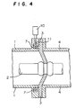
- Figure 4 is a cross-sectional view illustrating a current transformer of a gas insulated switching device according to Embodiment 4.
- flanges of a pressure container 1 and a metallic adaptor 5 are identical. Therefore, it is unnecessary to use the metallic adaptor 5, a dimension of the pressure container 1 in its axial direction is reduced, and a body of the switching device is miniaturized.
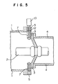
- FIG. 5 is a cross-sectional view illustrating a current transformer of a gas insulated switching device according to Embodiment 5 of the present invention.
- two Rogowskii coils 7 having same dimensions in an axial direction of a pressure container 1 and different dimensions in radial directions are concentrically arranged in a groove of a metallic adaptor 5. Therefore, the width of the metallic adaptor 5 in the axial direction is shortened to make a dimension of an entirety of the gas insulated switching device in its axial direction short, whereby the device is miniaturized.
- FIG. 6 a case that a structure of locating a current transformer in a connecting portion of pressure containers in the above-mentioned embodiments to an inside of a breaker container.
- Figure 6a is a cross-sectional view illustrating a breaker container of a gas insulated switching device according to Embodiment 6 of the present invention.
- Figure 6b is an enlarged view illustrating a current transformer located inside the breaker container.
- numerical reference 13 designates the breaker container;
- numerical reference 14 designates the breaker;
- numerical reference 15 designates an inner conductor connected to the breaker 14.
- an annular metallic adaptor having a groove is arranged in an outer periphery of the internal conductor 15 around an axis center thereof.
- two Rogowskii coils 7 having same diameters are arranged side by side in an axial direction of the metallic adaptor.
- an inner diameter of the metallic adaptor 5 may be the same as an inner diameter of the pressure container 1 or less.
- the gas insulated switching device may be a three-phase-bus and single-phase breaker type, a type that all three phases are simultaneously switched, and an isolated phase type.
- the breaker illustrated in Figure 6 is a vertically arranged type. However, the breaker may be a horizontally arranged type.
- the first advantage of the gas insulated switching device according to the present invention is that the dimensions of the pressure containers in the axial and radial directions are not increased, and an entire size of the switching device is miniaturized.
- the second advantage of the gas insulated switching device according to the present invention is that the hollow portion of the Rogowskii coils can be prevented from deforming, and a current can be detected with high accuracy.
- the third advantage of the gas insulated switching device according to the present invention is that an electric field around the triple junction can be relaxed.
- the fourth advantage of the gas insulated switching device according to the present invention is that an influence of a surge noise is suppressed, and it is possible to measure with high accuracy and high reliability.
- the fifth advantage of the gas insulated switching device according to the present invention is that the dimension of the pressure containers in the axial direction can be shortened, the dimension of the entire gas insulated switching device can be shortened, and therefore the gas insulated switching device is miniaturized.
- the sixth advantage of the gas insulated switching device according to the present invention is that the structure of attaching the Rogowskii coils to the metallic adaptor is simplified, and the Rogowskii coils can be produced at a low cost.
Landscapes
- Engineering & Computer Science (AREA)
- Power Engineering (AREA)
- Gas-Insulated Switchgears (AREA)
- Transformers For Measuring Instruments (AREA)
- Installation Of Bus-Bars (AREA)
Abstract
Description
- The present invention relates to a gas insulated switching device transforming an electrical energy in a power system, particularly to installation of a current transformer.
- A gas insulated switching device, used in a field of generating and transforming an electric power in a power system, is constructed by a switching device, a conductor, a current transformer, a surging arrester, and so on, which are accommodated in a metallic pressure container, filled with an arc-extinguishing gas such as a sulfur hexafluoride (hereinbelow referred to as SF6 gas) having excellent insulating capability and excellent arc-extinguishing capability, and these switching device, the conductor, the current transformer, the surging arrester, and so on are mutually connected, whereby the gas insulated switching device has been small-sized. However, further improvement in economy is required by reducing a space occupied by the gas insulated switching device by virtue of miniaturization and improvement in reliability of component obtained as a result of a recent technology development.
- Figure 7 is a cross-sectional view illustrating a conventional current transformer. In Figure 7,
numerical references conductor 2 is accommodated in a center thereof and an SF6 gas is filled.Numerical reference 3 designates an insulating spacer for supporting theconductor 2 and separating the gas in thepressure container 1 from the gas in theother pressure container 4, connected to apressure container 1.Numerical reference 6 designates a current transformer holder attached to flanges of thepressure containers insulating spacer 3, the current transformer holder includes a cylindrical portion having grooves like a ring and an attaching flange corresponding to the flanges of thepressure containers Numerical reference 7 designates a plurality of Rogowskii coils, positioned in the groove like the ring in thecurrent transformer holder 6 via aspacer 8 in an axial direction of thepressure container 1. Numerical reference 9 designates a fixing plate for fixing the Rogowskiicoils 7 inside the groove. A current transforming portion is constructed by thecurrent transformer holder 6, the Rogowskiicoils 7, thespacer 8, and the fixing plate 9 for detecting a current applied to theconductor 2. The Rogowskiicoils 7 is formed by uniformly wind a coil around a high molecular member, being flexible and having a circular cross sectional view or the like by many turns, wherein the Rogowskii coils work as a current sensor, from which a current signal is obtainable in proportion to a current value, flowing inside the Rogowskiicoils 7. - However, since the Rogowskii
coils 7 forming the current transformer are flexible, hollow portions of the Rogowskii coils are deformed by a pressure applied to surfaces of the Rogowskii coils at time of attaching these to thecurrent transformer holder 6, whereby an accuracy of detecting a current is deteriorated. - Further, since the Rogowskii
coils 7 are attached to thecurrent transformer holder 6 having protrusions in the axial directions of thepressure container 1, for example, in case that a breaker container containing a breaker and so on are connected, the protrusion of thecurrent transformer holder 6 insufficiently protrudes inside the breaker container, whereby the length of thepressure container 1 should be increased, and a miniaturization of an entirety of the switching device is difficult. - Further, although it is necessary to sufficiently keep an insulating distance between the Rogowskii coils and the
conductor 2, thecurrent transformer holder 6 also protrudes in a radial direction of thepressure container 1, whereby the diameter of the pressure container is increased, miniaturization of the entire switching device is difficult. - It is an object of the present invention to solve the above-mentioned problems inherent in the conventional technique and to provide a gas insulated switching device, in which a highly accurate current transformer is equipped for miniaturizing the gas insulated switching device.
- According to a first aspect of the present invention, there is provided a gas insulated switching device comprising a mutually connected series of containers having a conductor in a center and filled with an insulating and arc-extinguishing gas around the conductor; and a current transformer including Rogowskii coils for detecting a current flowing through the conductor, the current transformer is attached to a flange of the pressure containers through an annular metallic adaptor, wherein the current transformer is accommodated in grooves formed toward an inside of a metallic adaptor and uses the metallic adaptor to obtain an earth potential.
- According to a second aspect of the present invention, there is provided a gas insulated switching device, wherein the Rogowskii coils of the current transformer is formed by uniformly winding a coil around an inflexible insulating member by many turns.
- According to a third aspect of the present invention, there is provided a gas insulated switching device, wherein the metallic adaptor is attached via an insulating spacer for separating the gas in the mutually connected series containers, and a rounded portion is formed on an inner peripheral surface on a side, being in contact with the insulating spacer for relaxing an electric field in a triple junction among the insulating and arc-extinguishing gas filled in the pressure containers, the insulating spacer, and the metallic adaptor.
- According to a fourth aspect of the present invention, there is provided a gas insulated switching device, wherein a flange of the pressure containers is the metallic adaptor.
- According to a fifth aspect of the present invention, there is provided a gas insulated switching device, wherein a current detector for measuring the current, detected by the current converter, is located on an outer periphery of the metallic adaptor.
- According to a sixth aspect of the present invention, there is provided a gas insulated switching device, wherein the current transformer includes Rogowskii coils for detecting a current passing through the conductor, which are attached to a breaker in a breaker container being adjacent to and connected to the series of pressure containers through an angular metallic adaptor located in an outer periphery of the conductor connected to the breaker, and the current transformer is accommodated in a groove formed in the metallic adaptor toward an inside thereof, and uses the metallic adaptor to obtain an earth potential.
- According to a seventh aspect of the present invention, there is provided the gas insulated switching device, wherein a plurality of Rogowskii coils having same dimensions are arranged side by side in the metallic adaptor in an axial direction of the pressure containers around a common axis center of the Rogowskii coils.
- According to an eighth aspect a gas insulated switching device according to the present invention is that a plurality of Rogowskii coils having same dimensions in an axial direction of a cross section of the coils and different dimensions in radial directions of the coils are arranged in radial directions of the pressure containers so as to be concentrically piled up.
- According to a ninth aspect of the present invention, there is provided a gas insulated switching device wherein the Rogowskii coils is attached to the metallic adaptor by monolithically molding with a flexible resin inside the metallic adaptor.
- A more complete appreciation of the invention and many of the attendant advantages thereof will be readily obtained as the same becomes better understood by reference to the following detailed description when considered in connection with the accompanying drawings, wherein:
- Figure 1a is a cross-sectional view of a current
transformer of a gas insulated switching device according
to
Embodiment 1 of the present invention; - Figure 1b is an enlarged view illustrating the
current transformer of the gas insulated switching device
according to
Embodiment 1 of the present invention; - Figure 2 is a cross-sectional view illustrating a
current transformer of a gas insulated switching device
according to
Embodiment 2 of the present invention; - Figure 3 is a cross-sectional view of a current
transformer of a gas insulated switching device according
to
Embodiment 3 of the present invention; - Figure 4 is a cross-sectional view illustrating a
current transformer of a gas insulated switching device
according to
Embodiment 4 of the present invention; - Figure 5 is a cross-sectional view illustrating a
current transformer of a gas insulated switching device
according to
Embodiment 5 of the present invention; - Figure 6a is a cross-sectional view of a breaker
container of a gas insulated switching device according
to
Embodiment 6 of the present invention; - Figure 6b is an enlarged view of the breaker
container of the gas insulated switching device according
to
Embodiment 6 of the present invention; and - Figure 7 is a cross-sectional view illustrating a current transformer of a conventional gas insulated switching device.
-
- A detailed explanation will be given of preferred embodiments of the present invention in reference to Figures 1 through 6b as follows, wherein the same numerical references are used for the same or similar portions and description of these portions is omitted.
- Figure 1a is a cross-sectional view illustrating a current transformer of a gas insulated switching device according to
Embodiment 1 of the present invention. Figure 1b is an enlarged view of the current transformer. In Figures la and 1b,numerical references conductor 2 is accommodated in a center of the pressure containers.Numerical reference 3 designates an insulating spacer for supporting theconductor 2 and separating the gas in thepressure container 1 and theother pressure container 4 connected thereto.Numerical reference 5 designates an annular metallic adaptor attached to flanges of thepressure containers spacer 3.Numerical reference 7 designates a plurality of Rogowskii coils arranged in a groove formed in themetallic adaptor 5.Numerical reference 10 designates a current detector measuring a current detected by the current transformer including the Rogowskii coils.Numerical reference 11 designates a lead wire for connecting the Rogowskii coils 7 with thecurrent detector 10.Numerical reference 12 designates a resin having flexibility, by which themetallic adaptor 5 and the Rogowskii coils 7 are monolithically molded. The current transformer is fabricated by themetallic adaptor 5, the Rogowskii coils 7, thecurrent detector 10, and thelead wire 11 for detecting a current passing through theconductor 2. - Differences between
Embodiment 1 and the conventional technique is that, first, a current transformer holder in the conventional technique is changed to themetallic adaptor 5. Themetallic adaptor 5 according toEmbodiment 1 has the groove inside a body of themetallic adaptor 5. The Rogowskii coils 7 are accommodated in the groove, wherein a plurality of the Rogowskii coils 7 having same diameters are arranged side by side in an axial direction of thepressure container 1 around same axis centers, wherein two Rogowskii coils are exemplified in Figures la and 1b. - The
metallic adaptor 5 is attached to the flanges of thepressure containers current detector 10 is attached to an outer periphery of themetallic adaptor 5, which is connected to the Rogowskii coils 7 through alead wire 11. Further, a rounded portion is formed in an inner diameter of themetallic adaptor 5 on a side in contact with the insulatingspacer 3. The rounded portion is to relax an electric field in a triple junction among the insulating and arc-extinguishing gas filled in thepressure containers spacer 3, and themetallic adaptor 5. - Second, although in a conventional technique the coil having many turns is uniformly wound around the insulating member having flexibility, an inflexible insulating member is used for the Rogowskii coils 7 in
Embodiment 1. A material of the Rogowskii coils 7 is an epoxy laminating resin with a glass fabric base, a phenol laminating resin with a paper base, FRP and so on. - On the other hand, the Rogowskii coils are monolithically molded by the resin having flexibility inside the groove of the
metallic adaptor 5. By monolithically molding the Rogowskii coils, it is possible to obtain the current transformer, which can be easily operated and simply installed, at a low cost. A method of monolithically molding the Rogowskiicoils 7 is injection of a silicon system resin, an epoxy system resin, a butyl system resin, and so on respectively having excellent anti-arced gas property. Further, it is possible to apply a conventional method of producing the Rogowskii coils such that a resin is impregnated after winding an insulating tape. - As described, according to
Embodiment 1, since the Rogowskiicoils 7 are arranged in the groove of themetallic adaptor 5 without protruding portions, it is possible to prevent sizes in the axial and radial directions of thepressure container 1 from increasing, and an entire size of the switching device can be miniaturized. - Further, since the Rogowskii coils 7 is obtained by winding the coil around the insulating member without flexibility, it is possible to suppress deformation of hollow portions of the Rogowskii coils 7, and the current can be detected with high accuracy.
- Figure 2 is a cross-sectional view illustrating a current transformer of a gas insulated switching device according to
Embodiment 2 of the present invention. A difference fromEmbodiment 1 is that a flange of apressure container 1 overlaps a groove accommodating the Rogowskii coil because thepressure container 1 and apressure container 4 have same diameters. Therefore, a cut-out 15 is formed in the flange of thepressure container 1 so as not to clog an opening portion of the groove. Accordingly, it is possible to obtain an effect of matching the diameter of thepressure container 1 with the diameter of thepressure container 4 and making the diameters of thepressure containers - Figure 3 is a cross-sectional view illustrating a current transformer of a gas insulated switching device according to
Embodiment 3 of the present invention. InEmbodiment 3, an opening portion of a groove in ametallic adaptor 5 is formed to face a side of an insulatingspacer 3. Therefore, as inEmbodiment 2, it is unnecessary to form a cut-out in a flange of a pressure container, and processing of the flange of thepressure container 1 is simplified, whereby an effect of producing at a low cost is obtainable. - Figure 4 is a cross-sectional view illustrating a current transformer of a gas insulated switching device according to
Embodiment 4. Inembodiment 4, flanges of apressure container 1 and ametallic adaptor 5 are identical. Therefore, it is unnecessary to use themetallic adaptor 5, a dimension of thepressure container 1 in its axial direction is reduced, and a body of the switching device is miniaturized. - Figure 5 is a cross-sectional view illustrating a current transformer of a gas insulated switching device according to
Embodiment 5 of the present invention. InEmbodiment 5, twoRogowskii coils 7 having same dimensions in an axial direction of apressure container 1 and different dimensions in radial directions are concentrically arranged in a groove of ametallic adaptor 5. Therefore, the width of themetallic adaptor 5 in the axial direction is shortened to make a dimension of an entirety of the gas insulated switching device in its axial direction short, whereby the device is miniaturized. - Further, in
Embodiment 5, a case that the Rogowskii coils having the same dimensions in the axial direction of thepressure container 1 and different dimensions in the radial direction are concentrically arranged in the groove of themetallic adaptor 5, such a structure can be respectively applied to the above-mentioned embodiments. - In
Embodiment 6, a case that a structure of locating a current transformer in a connecting portion of pressure containers in the above-mentioned embodiments to an inside of a breaker container. Figure 6a is a cross-sectional view illustrating a breaker container of a gas insulated switching device according toEmbodiment 6 of the present invention. Figure 6b is an enlarged view illustrating a current transformer located inside the breaker container. In Figures 6a and 6b,numerical reference 13 designates the breaker container;numerical reference 14 designates the breaker; andnumerical reference 15 designates an inner conductor connected to thebreaker 14. - As illustrated in Figure 6a and 6b, an annular metallic adaptor having a groove is arranged in an outer periphery of the
internal conductor 15 around an axis center thereof. In the groove of themetallic adaptor 5, twoRogowskii coils 7 having same diameters are arranged side by side in an axial direction of the metallic adaptor. Although a structure around themetallic adaptor 5 inside the breaker container is similar to that illustrated in Figure 1, structures respectively described in the above-mentioned embodiments can be applied toEmbodiment 6. - Further, in the above-mentioned embodiments, a case that the two
Rogowskii coils 7 are used. However, the present invention is not limited to the case, and three or more Rogowskii coils 7 may be used. Further, in Figures la through 5, an inner diameter of themetallic adaptor 5 may be the same as an inner diameter of thepressure container 1 or less. Further, the gas insulated switching device may be a three-phase-bus and single-phase breaker type, a type that all three phases are simultaneously switched, and an isolated phase type. The breaker illustrated in Figure 6 is a vertically arranged type. However, the breaker may be a horizontally arranged type. - The first advantage of the gas insulated switching device according to the present invention is that the dimensions of the pressure containers in the axial and radial directions are not increased, and an entire size of the switching device is miniaturized.
- The second advantage of the gas insulated switching device according to the present invention is that the hollow portion of the Rogowskii coils can be prevented from deforming, and a current can be detected with high accuracy.
- The third advantage of the gas insulated switching device according to the present invention is that an electric field around the triple junction can be relaxed.
- The fourth advantage of the gas insulated switching device according to the present invention is that an influence of a surge noise is suppressed, and it is possible to measure with high accuracy and high reliability.
- The fifth advantage of the gas insulated switching device according to the present invention is that the dimension of the pressure containers in the axial direction can be shortened, the dimension of the entire gas insulated switching device can be shortened, and therefore the gas insulated switching device is miniaturized.
- The sixth advantage of the gas insulated switching device according to the present invention is that the structure of attaching the Rogowskii coils to the metallic adaptor is simplified, and the Rogowskii coils can be produced at a low cost.
- Obviously, numerous modifications and variations of the present invention are possible in light of the above teachings. It is therefore to be understood that within the scope of the appended claims, the invention may be practiced otherwise than as specifically described herein.
- The entire disclosure of Japanese Patent Application JP11-368756 filed on December 27, 1999 including specification, claims, drawings and summary are incorporated herein by reference in its entirety.
Claims (9)
- A gas insulated switching device comprising:a series of pressure containers (1,4) mutually connected, in which a conductor (2) is positioned in an inside center, and an insulating and arc-extinguishing gas is filled in a space around the conductor; anda current transformer fabricated by Rogowskii coils (7) for detecting a current passing through the conductor, the current transformer is attached to flanges of the pressure containers via an annular metallic adaptor (5),wherein the current transformer is accommodated in a groove formed in the metallic adaptor toward an inside of the metallic adaptor and uses the metallic adaptor to obtain an earth potential.
- The gas insulated switching device according to Claim 1,
wherein the Rogowskii coils (7) of the current transformer is formed by uniformly winding a coil around an inflexible insulating member by many turns. - The gas insulated switching device according to Claim 1 or 2,wherein the metallic adaptor is attached to the pressure container via an insulating spacer (3) for separating the gas in the series of the pressure containers, anda rounded portion is formed in an inner peripheral surface on a side in contact with the insulating spacer to relax an electric field in a triple junction, formed among the insulating and arc-extinguishing gas filled in the pressure containers, the insulating spacer, and the metallic adaptor.
- The gas insulated switching device according to Claim 1 or 2,
wherein a flange of the pressure containers is the metallic adaptor. - The gas insulated switching device according to Claim 1 or 2,
wherein a current detector (10) for measuring the current detected by the current transformer is located on an outer periphery of the metallic adaptor. - The gas insulated switching device according to Claim 1 or 2, further comprising:a breaker (14) located inside a breaker container (13), which is closely joined to the series of pressure containers,wherein the current transformer is fabricated by the Rogowskii coils (7) for detecting the current passing through the conductor (2), connected to the breaker, by attaching the annular metallic adaptor located in the outer periphery of the conductor to the pressure containers, (1), andthe current transformer is accommodated in the groove, formed in the metallic adaptor toward an inside of the metallic adaptor, to use the metallic adaptor as an earth potential.
- The gas insulated switching device according to Claim 1 or 2,
wherein a plurality of the Rogowskii coils having same dimensions are concentrically arranged in the metallic adaptor in an axial direction of the pressure containers. - The gas insulated switching device according Claim 1 or 2,
wherein a plurality of the Rogowskii coils having a same dimension in axial directions in a cross section of the coils and different dimensions in radial directions of the coils are concentrically arranged in radial directions of the pressure containers so as to surround and being surrounded. - The gas insulated switching device according to Claim 1 or 2,
wherein the Rogowskii coils are monolithically molded by a flexible resin inside the metallic adaptor.
Applications Claiming Priority (2)
| Application Number | Priority Date | Filing Date | Title |
|---|---|---|---|
| JP36875699A JP3774604B2 (en) | 1999-12-27 | 1999-12-27 | Gas insulated switchgear |
| JP36875699 | 1999-12-27 |
Publications (2)
| Publication Number | Publication Date |
|---|---|
| EP1113550A1 true EP1113550A1 (en) | 2001-07-04 |
| EP1113550B1 EP1113550B1 (en) | 2005-11-02 |
Family
ID=18492672
Family Applications (1)
| Application Number | Title | Priority Date | Filing Date |
|---|---|---|---|
| EP00114534A Revoked EP1113550B1 (en) | 1999-12-27 | 2000-07-06 | Current transformer for a gas insulated switchgear |
Country Status (5)
| Country | Link |
|---|---|
| US (1) | US6424059B1 (en) |
| EP (1) | EP1113550B1 (en) |
| JP (1) | JP3774604B2 (en) |
| CN (1) | CN1207831C (en) |
| DE (1) | DE60023641T2 (en) |
Cited By (2)
| Publication number | Priority date | Publication date | Assignee | Title |
|---|---|---|---|---|
| WO2011036241A1 (en) * | 2009-09-25 | 2011-03-31 | Areva T&D Sas | Electrical conductor casing provided with current sensors |
| AT506142B1 (en) * | 2007-11-09 | 2012-01-15 | Kuvag Gmbh & Co Kg | ELECTRODE FOR HIGH-RESISTANCE SCHOTT INSULATORS |
Families Citing this family (16)
| Publication number | Priority date | Publication date | Assignee | Title |
|---|---|---|---|---|
| JP3774604B2 (en) * | 1999-12-27 | 2006-05-17 | 三菱電機株式会社 | Gas insulated switchgear |
| DE502004002290D1 (en) * | 2004-02-27 | 2007-01-25 | Abb Technology Ag | Compact current transformer housing for gas-insulated switchgear |
| KR100679086B1 (en) | 2004-12-30 | 2007-02-05 | (주) 피에스디테크 | Ultra-high voltage power equipment with integrated broadband high-frequency partial discharge diagnostic sensor |
| JP4764139B2 (en) * | 2005-11-04 | 2011-08-31 | 株式会社日本Aeパワーシステムズ | Connection structure of gas insulated switchgear and oil-filled transformer |
| KR100760331B1 (en) | 2006-03-30 | 2007-09-20 | 신성산전주식회사 | High speed failure section automatic shut-off device |
| DE102006040037A1 (en) * | 2006-08-23 | 2008-02-28 | Siemens Ag | Connection module with an encapsulating housing |
| JP4712128B1 (en) * | 2010-09-29 | 2011-06-29 | 三菱電機株式会社 | Gas insulated switchgear |
| CN103534888B (en) * | 2011-04-08 | 2015-09-23 | 三菱电机株式会社 | Gas-insulated switchgear device |
| CN104143777A (en) * | 2013-11-14 | 2014-11-12 | 国家电网公司 | Gas-insulated metal-enclosed switchgear and single phase thereof |
| CN107887793B (en) * | 2016-09-30 | 2020-08-04 | 中国电力科学研究院 | A Contact Box Based on Integrated Discrete Rogowski Coils |
| KR102066227B1 (en) * | 2018-04-27 | 2020-01-14 | 엘에스산전 주식회사 | Gas Insulated Switchgear |
| CN109101976B (en) * | 2018-07-10 | 2021-11-30 | 温州大学 | Method for detecting surface defects of arc-extinguishing grid plate |
| DE102018219803A1 (en) * | 2018-11-19 | 2020-05-20 | Siemens Aktiengesellschaft | Current transformer module for a switchgear and corresponding switchgear |
| DE102020212350A1 (en) * | 2020-09-30 | 2022-03-31 | Siemens Energy Global GmbH & Co. KG | Encapsulated high-voltage device and current transformer for the encapsulated high-voltage device |
| KR102563389B1 (en) * | 2021-03-26 | 2023-08-07 | 한국해양대학교 산학협력단 | Structure Design and Fabrication Techniques of a Rogowski Current Sensor Embedded inside the Spacer of GISs |
| DE112023001219T5 (en) * | 2022-03-03 | 2025-01-16 | Asahi Kasei Microdevices Corporation | current sensor and current detection method |
Citations (5)
| Publication number | Priority date | Publication date | Assignee | Title |
|---|---|---|---|---|
| US3959761A (en) * | 1974-04-08 | 1976-05-25 | Messwandler-Bau Gmbh | Single conductor current transformer adapted to be installed into a fully insulated, metal-encapsulated high-voltage switching installation |
| US5272460A (en) * | 1991-04-22 | 1993-12-21 | Asea Brown Boveri Ltd | Current and voltage transformer for a metal-encapsulated, gas-insulated high-voltage installation |
| EP0650236A1 (en) * | 1993-10-26 | 1995-04-26 | Siemens Aktiengesellschaft | Electrical high voltage switchgear with toroidal core current transformer |
| EP0838686A2 (en) * | 1996-10-23 | 1998-04-29 | General Electric Company | Self-powered axial current sensor |
| US5939876A (en) * | 1996-08-23 | 1999-08-17 | Asea Brown Boveri Ag | Measuring device for a metal-enclosed, gas-insulated high-voltage installation |
Family Cites Families (5)
| Publication number | Priority date | Publication date | Assignee | Title |
|---|---|---|---|---|
| DE4121654A1 (en) | 1991-06-29 | 1993-01-07 | Asea Brown Boveri | COMBINED CURRENT AND VOLTAGE CONVERTER FOR A METAL-ENCLOSED GAS-INSULATED HIGH-VOLTAGE SYSTEM |
| DE59700650D1 (en) * | 1996-08-23 | 1999-12-09 | Asea Brown Boveri | Housing with a ventilation device for an electronic device |
| EP0825447B1 (en) * | 1996-08-23 | 2008-04-02 | ABB Schweiz AG | Measuring device for a metal-encapsulated gas-insulated high voltage installation |
| FI109153B (en) * | 1998-01-30 | 2002-05-31 | Abb Technology Ltd | Piece of insulation blank with a continuous primary current line |
| JP3774604B2 (en) * | 1999-12-27 | 2006-05-17 | 三菱電機株式会社 | Gas insulated switchgear |
-
1999
- 1999-12-27 JP JP36875699A patent/JP3774604B2/en not_active Expired - Fee Related
-
2000
- 2000-07-06 EP EP00114534A patent/EP1113550B1/en not_active Revoked
- 2000-07-06 US US09/611,130 patent/US6424059B1/en not_active Expired - Lifetime
- 2000-07-06 DE DE60023641T patent/DE60023641T2/en not_active Expired - Lifetime
- 2000-08-14 CN CNB00124194XA patent/CN1207831C/en not_active Expired - Fee Related
Patent Citations (5)
| Publication number | Priority date | Publication date | Assignee | Title |
|---|---|---|---|---|
| US3959761A (en) * | 1974-04-08 | 1976-05-25 | Messwandler-Bau Gmbh | Single conductor current transformer adapted to be installed into a fully insulated, metal-encapsulated high-voltage switching installation |
| US5272460A (en) * | 1991-04-22 | 1993-12-21 | Asea Brown Boveri Ltd | Current and voltage transformer for a metal-encapsulated, gas-insulated high-voltage installation |
| EP0650236A1 (en) * | 1993-10-26 | 1995-04-26 | Siemens Aktiengesellschaft | Electrical high voltage switchgear with toroidal core current transformer |
| US5939876A (en) * | 1996-08-23 | 1999-08-17 | Asea Brown Boveri Ag | Measuring device for a metal-enclosed, gas-insulated high-voltage installation |
| EP0838686A2 (en) * | 1996-10-23 | 1998-04-29 | General Electric Company | Self-powered axial current sensor |
Cited By (5)
| Publication number | Priority date | Publication date | Assignee | Title |
|---|---|---|---|---|
| AT506142B1 (en) * | 2007-11-09 | 2012-01-15 | Kuvag Gmbh & Co Kg | ELECTRODE FOR HIGH-RESISTANCE SCHOTT INSULATORS |
| WO2011036241A1 (en) * | 2009-09-25 | 2011-03-31 | Areva T&D Sas | Electrical conductor casing provided with current sensors |
| FR2950748A1 (en) * | 2009-09-25 | 2011-04-01 | Areva T & D Sas | ELECTRICAL CONDUCTOR ENVELOPE PROVIDED WITH CURRENT SENSORS |
| CN102648557A (en) * | 2009-09-25 | 2012-08-22 | 奥斯特姆科技有限公司 | Electrical conductor casing provided with current sensors |
| CN102648557B (en) * | 2009-09-25 | 2016-03-23 | 阿尔斯通技术有限公司 | Be provided with the electric conductor shell of current sensor |
Also Published As
| Publication number | Publication date |
|---|---|
| DE60023641T2 (en) | 2006-07-20 |
| JP2001186611A (en) | 2001-07-06 |
| US6424059B1 (en) | 2002-07-23 |
| JP3774604B2 (en) | 2006-05-17 |
| HK1038108A1 (en) | 2002-03-01 |
| EP1113550B1 (en) | 2005-11-02 |
| CN1207831C (en) | 2005-06-22 |
| DE60023641D1 (en) | 2005-12-08 |
| CN1308398A (en) | 2001-08-15 |
Similar Documents
| Publication | Publication Date | Title |
|---|---|---|
| US6424059B1 (en) | Gas insulated switching device | |
| CN104813175B (en) | For the electric current and/or voltage sensing device of comprehensive purposes | |
| US6680665B2 (en) | Three-phase current transformer | |
| CN104169726B (en) | Measuring transducer device | |
| EP2312717A2 (en) | Overhead line engagement bushing | |
| US11658535B2 (en) | Apparatus for driving a compressor and method for assembling the apparatus | |
| KR20130047695A (en) | Current transformer device | |
| JP4472553B2 (en) | Small current transformer casing for gas-insulated switchgear | |
| US3953815A (en) | Cast-resin insulated instrument transformer, in particular potential transformer | |
| US3943433A (en) | Measuring transformer arrangement for a high-voltage installation carrying several conductors | |
| US6414257B1 (en) | Gas-insulated circuit-breaker with an integrated electronic current transformer | |
| CN114731088B (en) | Device for driving a compressor and method for manufacturing the device | |
| US12283859B2 (en) | Motor having insulator on which terminals are seated | |
| JPH0518450B2 (en) | ||
| US20260106054A1 (en) | Pole Part | |
| JP2007129851A (en) | Connection structure of gas insulated switchgear and oil-filled transformer | |
| JP2001230136A (en) | Instrument transformer | |
| JPH11111539A (en) | Stationary induction electrical equipment | |
| JPH0161007B2 (en) | ||
| JPH0625953Y2 (en) | Gas insulated capacitor | |
| JP2000193685A (en) | Optical voltage sensor | |
| HK1038108B (en) | Gas insulated switching device | |
| US6552641B1 (en) | Transformer, especially for powering cathode ray tubes | |
| JP2002271925A (en) | Current transformer for gas insulated switchgear | |
| JPH03159217A (en) | Transformer |
Legal Events
| Date | Code | Title | Description |
|---|---|---|---|
| PUAI | Public reference made under article 153(3) epc to a published international application that has entered the european phase |
Free format text: ORIGINAL CODE: 0009012 |
|
| 17P | Request for examination filed |
Effective date: 20001109 |
|
| AK | Designated contracting states |
Kind code of ref document: A1 Designated state(s): AT BE CH CY DE DK ES FI FR GB GR IE IT LI LU MC NL PT SE |
|
| AX | Request for extension of the european patent |
Free format text: AL;LT;LV;MK;RO;SI |
|
| AKX | Designation fees paid |
Free format text: DE FR |
|
| 17Q | First examination report despatched |
Effective date: 20031205 |
|
| GRAP | Despatch of communication of intention to grant a patent |
Free format text: ORIGINAL CODE: EPIDOSNIGR1 |
|
| GRAS | Grant fee paid |
Free format text: ORIGINAL CODE: EPIDOSNIGR3 |
|
| GRAA | (expected) grant |
Free format text: ORIGINAL CODE: 0009210 |
|
| AK | Designated contracting states |
Kind code of ref document: B1 Designated state(s): DE FR |
|
| REF | Corresponds to: |
Ref document number: 60023641 Country of ref document: DE Date of ref document: 20051208 Kind code of ref document: P |
|
| RAP2 | Party data changed (patent owner data changed or rights of a patent transferred) |
Owner name: MITSUBISHI DENKI KABUSHIKI KAISHA |
|
| ET | Fr: translation filed | ||
| PLBI | Opposition filed |
Free format text: ORIGINAL CODE: 0009260 |
|
| PLAX | Notice of opposition and request to file observation + time limit sent |
Free format text: ORIGINAL CODE: EPIDOSNOBS2 |
|
| 26 | Opposition filed |
Opponent name: SIEMENS AG Effective date: 20060731 |
|
| PLAF | Information modified related to communication of a notice of opposition and request to file observations + time limit |
Free format text: ORIGINAL CODE: EPIDOSCOBS2 |
|
| PLBB | Reply of patent proprietor to notice(s) of opposition received |
Free format text: ORIGINAL CODE: EPIDOSNOBS3 |
|
| RDAF | Communication despatched that patent is revoked |
Free format text: ORIGINAL CODE: EPIDOSNREV1 |
|
| APBM | Appeal reference recorded |
Free format text: ORIGINAL CODE: EPIDOSNREFNO |
|
| APBP | Date of receipt of notice of appeal recorded |
Free format text: ORIGINAL CODE: EPIDOSNNOA2O |
|
| APAH | Appeal reference modified |
Free format text: ORIGINAL CODE: EPIDOSCREFNO |
|
| APBQ | Date of receipt of statement of grounds of appeal recorded |
Free format text: ORIGINAL CODE: EPIDOSNNOA3O |
|
| REG | Reference to a national code |
Ref country code: DE Ref legal event code: R064 Ref document number: 60023641 Country of ref document: DE Ref country code: DE Ref legal event code: R103 Ref document number: 60023641 Country of ref document: DE |
|
| APBU | Appeal procedure closed |
Free format text: ORIGINAL CODE: EPIDOSNNOA9O |
|
| PGFP | Annual fee paid to national office [announced via postgrant information from national office to epo] |
Ref country code: FR Payment date: 20120719 Year of fee payment: 13 Ref country code: DE Payment date: 20120704 Year of fee payment: 13 |
|
| RDAG | Patent revoked |
Free format text: ORIGINAL CODE: 0009271 |
|
| STAA | Information on the status of an ep patent application or granted ep patent |
Free format text: STATUS: PATENT REVOKED |
|
| 27W | Patent revoked |
Effective date: 20121023 |
|
| REG | Reference to a national code |
Ref country code: DE Ref legal event code: R107 Ref document number: 60023641 Country of ref document: DE Effective date: 20130508 |