EP1113537A2 - Connector - Google Patents
Connector Download PDFInfo
- Publication number
- EP1113537A2 EP1113537A2 EP00310469A EP00310469A EP1113537A2 EP 1113537 A2 EP1113537 A2 EP 1113537A2 EP 00310469 A EP00310469 A EP 00310469A EP 00310469 A EP00310469 A EP 00310469A EP 1113537 A2 EP1113537 A2 EP 1113537A2
- Authority
- EP
- European Patent Office
- Prior art keywords
- detecting member
- housings
- housing
- locking arm
- detecting
- Prior art date
- Legal status (The legal status is an assumption and is not a legal conclusion. Google has not performed a legal analysis and makes no representation as to the accuracy of the status listed.)
- Withdrawn
Links
Images




Classifications
-
- H—ELECTRICITY
- H01—ELECTRIC ELEMENTS
- H01R—ELECTRICALLY-CONDUCTIVE CONNECTIONS; STRUCTURAL ASSOCIATIONS OF A PLURALITY OF MUTUALLY-INSULATED ELECTRICAL CONNECTING ELEMENTS; COUPLING DEVICES; CURRENT COLLECTORS
- H01R13/00—Details of coupling devices of the kinds covered by groups H01R12/70 or H01R24/00 - H01R33/00
- H01R13/62—Means for facilitating engagement or disengagement of coupling parts or for holding them in engagement
- H01R13/627—Snap or like fastening
- H01R13/6271—Latching means integral with the housing
- H01R13/6272—Latching means integral with the housing comprising a single latching arm
-
- H—ELECTRICITY
- H01—ELECTRIC ELEMENTS
- H01R—ELECTRICALLY-CONDUCTIVE CONNECTIONS; STRUCTURAL ASSOCIATIONS OF A PLURALITY OF MUTUALLY-INSULATED ELECTRICAL CONNECTING ELEMENTS; COUPLING DEVICES; CURRENT COLLECTORS
- H01R13/00—Details of coupling devices of the kinds covered by groups H01R12/70 or H01R24/00 - H01R33/00
- H01R13/62—Means for facilitating engagement or disengagement of coupling parts or for holding them in engagement
- H01R13/639—Additional means for holding or locking coupling parts together, after engagement, e.g. separate keylock, retainer strap
-
- H—ELECTRICITY
- H01—ELECTRIC ELEMENTS
- H01R—ELECTRICALLY-CONDUCTIVE CONNECTIONS; STRUCTURAL ASSOCIATIONS OF A PLURALITY OF MUTUALLY-INSULATED ELECTRICAL CONNECTING ELEMENTS; COUPLING DEVICES; CURRENT COLLECTORS
- H01R13/00—Details of coupling devices of the kinds covered by groups H01R12/70 or H01R24/00 - H01R33/00
- H01R13/64—Means for preventing incorrect coupling
- H01R13/641—Means for preventing incorrect coupling by indicating incorrect coupling; by indicating correct or full engagement
Definitions
- the present invention relates to an electrical connector provided with a fitting detecting function.
- JP 4-33666 One conventional example of this type of connector is described in JP 4-33666.
- one of a pair of housings capable of fitting mutually together is provided with a locking arm which bends resiliently as the two housings are being fitted together, returns to its original position when the two housings are correctly fitted together, and retains the other housing.
- This housing is also provided with a detecting member capable of being inserted from the exterior into the interior of the space along which the locking arm moves. The locking arm makes contact with the detecting member as this locking arm moves resiliently, thereby regulating the insertion of the detecting member. By this means, it can be detected whether the two housings have been correctly fitted together.
- This detecting member is comparatively small. Consequently, it may be dropped and lost as it is inserted into or removed from the housing. As a result, the detecting member is kept attached in a temporary position to the exterior of the space along which the locking arm moves.
- components which retain the detecting member in an unremovable state when it is in the temporary position consist of a stepped member which protrudes from a side face of the detecting member, and a protrusion which engages with the stepped member and which is provided on a side wall that guides the sliding of the detecting member.
- These components are bulky, particularly in the width-wise direction of the housing (the direction at a right-angle to the direction of insertion of the detecting member), and could be improved.
- the present invention has taken the above problem into consideration, and aims to provide this improvement.
- an electrical connector comprising two mutually engageable connector housings, one of said housings having a resilient latching arm for engaging and retaining the other of said housings in a fully fitted condition, said latching arm having a bending space to permit bending thereof during movement of said housings through a half fitted condition to the fully fitted condition, and wherein a detecting member is insertable from the exterior into said bending space, insertion of said detecting member being prevented by bending of said latching arm in the half fitted condition.
- the latching arm is a cantilever having a free end engageable by a frame-like aperture of said detecting member, the detecting member being slidable on said one housing in the direction of attachment with said other housing.
- the detecting member has a resilient elongate member extending in said attachment direction and engageable by an abutment of said one connector housing to prevent movement into said bending space, a releasing member of the other connector housing bending said elongate member out of engagement with said abutment to permit movement into said bending space when said latching member is not bent.
- the detecting member preferably has two parallel elongate members in mirror image and having mutually facing recesses for engagement by respective abutment members of said other housing.
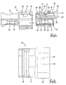
- the present embodiment is provided with a male connector housing 10, and a female connector housing 20, these two housings 10 and 20 being capable of being fitted together.
- the female housing 20 is provided with a locking arm 26, for locking the two housings 10 and 20 in a locked state, and a detecting member 35 for detecting whether the two housings 10 and 20 have been correctly fitted together.
- the fitting face sides of the two housings 10 and 20 are considered to be the anterior sides.
- the male housing 10 has a terminal housing chamber 11 which has a flat block shape.
- An approximately angular tubular hood 12 is provided on an anterior side of the terminal housing chamber 11.
- Cavities 13 are formed along the entire width of the terminal housing chamber 11 in a lower layer and are formed in the vicinity of a central portion thereof in an upper layer.
- Male terminal fittings (not shown) are inserted from the posterior into each cavity 13 and engage with lances 14 provided on ceiling faces of the cavities 13, and tabs of the male terminal fittings protrude into the hood 12 and are housed therein an unremovable state. The male terminal fittings are then doubly retained by a side retainer 15.
- the female housing 20 has a flat block shape, an anterior side thereof fitting into the hood 12 of the male housing 10.
- Cavities 21 are formed within the female housing 20 so as to correspond to the cavities 13 of the male housing 10, these being formed along the entire width of the female housing 20 in a lower layer and in the vicinity of a central portion thereof in an upper layer.
- Female terminal fittings (not shown) are inserted from the posterior into each cavity 21 and engage with lances 22 provided on ceiling faces of the cavities 21. The female terminal fittings are thereby housed in an unremovable state and are subsequently doubly retained by a side retainer 23.
- the portion of the female housing 20 which is not provided with the upper layer of cavities 13 has a housing groove 25 formed therein.
- This housing groove 25 faces an anterior-posterior direction, the locking arm 26 being formed therein in a central portion thereof relative to its width-wise direction.
- the locking arm 26 has two arm members 27 which are formed in a parallel manner with a space therebetween. These arm members 27 rise upwards from an anterior end (the left side in Figure 6) of the housing groove 25 and extend towards the posterior. Upper faces of extending ends of the arm members 27 are joined by a pressing member 28, these extending ends being capable of moving downwards.
- a locking member 30 is formed between the arm members 27 at an approximately central location relative to the length-wise direction thereof. An upper face of an anterior edge of this locking member 30 forms a tapered guiding face 31.
- a protrusion 16 is formed on the hood 12 of the male housing 10 at a location corresponding to the locking arm 26. An anterior edge of this protrusion 16 faces downwards.
- the protrusion 16 makes contact with the guiding face 31 of the locking member 30 of the locking arm 26 while the female housing 20 is being fitted into the hood 12 of the male housing 10. Consequently, the locking arm 26 is bent downwards as it is being pushed inwards.
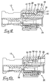
- the female housing 20 is pushed in to the correct fitting position so that it reaches an inner wall of the hood 12, the locking member 30 passed the protrusion 16, the locking arm 26 then returns to its original position, and the locking member 30 engages with the protrusion 16, thereby locking the two housings 10 and 20 in the correctly fitted state (see Figure 15).
- the detecting member 35 for detecting whether the two housings 10 and 20 are in the correctly fitted state is attached to the housing groove 25 of the female housing 20.
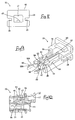
- the detecting member 35 is made from plastic and is formed as shown in Figures 7 to 9.
- the detecting member 35 has a base member 36 which fits tightly with the housing groove 25 along its width-wise direction. This base member 36 also serves to facilitate the insertion of the detecting member 35.
- the base member 36 has a square frame shape, a central portion thereof forming a fitting hole 37 into which the extending ends of the locking arm 26 can be fitted.
- Guiding grooves 38 are formed in an anterior-posterior direction in left and right faces of the base member 36 and, as shown in Figure 5, guiding plates 39 protrude from opening sides of left and right side walls of the housing groove 25 of the female housing 20. These guiding plates 39 fit with the guiding grooves 38 in a manner whereby they slide freely therein. Furthermore, a catching member 40, which is used to return the detecting member 35 to the posterior, protrudes upwards from an upper face of a posterior end of the base member 36.
- a lower portion of the anterior face of the base member 36 is provided with a retaining rod 42 which protrudes therefrom at a central location relative to the width-wise direction thereof, and a pair of contacting rods 43 which protrude along both sides of the retaining rod 42 and are separated from it by a specified distance.
- the retaining rod 42 and the contacting rods 43 have a square bar shape when seen from a vertical length-wise cross-sectional view, and the tips thereof protrude to the same extent.
- the detecting member 35 When the detecting member 35 is in a state whereby the base member 36 is fully fitted with the housing groove 25 and the lower faces of the detecting member 35 make contact with a groove base from the base member 36 to the contacting rods 43, the detecting member 35 can move smoothly within the housing groove 25 along the guiding plates 39.
- the arm members 27 of the locking arm 26 After the detecting member 35 has been attached within the housing groove 25, the arm members 27 of the locking arm 26 come to be located in the spaces between the retaining rod 42 and the contacting rods 43 at both sides of this retaining rod 42. Spaces are formed between the contacting rods 43 and side faces of the housing groove 25, these contacting rods 43 being capable of bending towards the side faces of the housing groove 25.
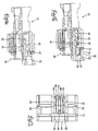
- a pair of left and right stoppers 45 are formed on the base of the housing groove 25 at locations towards an anterior end thereof. As shown in Figures 10 and 11, these stoppers 45 make contact with lower inner ends of anterior end faces of the contacting rods 43 of the detecting member 35.
- a retaining hook 47 which is capable of engaging with the locking member 30 of the locking arm 26, protrudes from an upper face of an anterior end face of the retaining rod 42. An upper portion of an anterior face of this retaining hook 47 forms an inclined guiding face 48.
- a recessed member 49 for the locking member 30 is formed directly to the posterior of the retaining hook 47.
- the detecting member 35 is attached in the temporary position within the housing groove 25 before the retainer 23 is attached in a main retaining position. While the detecting member 35 is being inserted from the posterior into the housing groove 25, the guiding face 48 of the retaining hook 47 of the retaining rod 42 makes contact with the locking member 30 of the locking arm 26, the locking arm 26 is bent slightly upwards, and the detecting member 35 is pushed inwards. Then the two contacting rods 43 make contact with the corresponding stoppers 45, thereby halting the insertion process.
- the retaining hook 47 passes the locking member 30, thereby allowing the locking arm 26 to return to its original position, and the retaining hook 47 enters a space to the anterior of the locking member 30, thereby retaining detecting members 35 in the posterior direction.
- the locking arm 26 In this temporary attaching position, as shown in Figure 1, the locking arm 26 is in a state whereby the extending ends thereof can bend downwards. That is, the extending ends of this locking arm 26 are located to the anterior of the base member 36 of the detecting member 35, and he locking member 30 is located above the recessed member 49.
- a pair of releasing members 50 for releasing the engaged state of the detecting member 3 is in the anterior direction, are formed on a ceiling face of the hood 12 of the male housing 10. As shown in Figure 7, these releasing members 50 protrude downwards from a central location relative to the length-wise direction of the ceiling face, and make sliding contact with upper, inner ends of the anterior end faces of the contacting rods 43.
- the releasing members 50 have a cross-sectionally angles shape, having inclined faces 50A on both sides, the apexes thereof facing opposing sides.
- Contacting members 53 and upper stopping holes 54 are formed on inner faces of upper portions of the two retaining rods 43.
- the contacting members 53 which have a cross-sectionally angled shape corresponding to the shape of the releasing members 50, are formed closer to the anterior ends of the contacting rods 43 than the concave-shaped upper stopping holes 54.
- the contacting rods 43 return to their original straight state immediately after the contacting members 53 have passed the releasing members 50, and the releasing members 50 fit with the upper stopping holes 54.
- anterior outer corners of the stoppers 45 which make contact with the anterior ends of the contacting rods 43, form inclined faces 45A.
- lower stopping holes 56 are formed in lower inner faces of the contacting rods 43 at a specified distance from the anterior ends thereof. These lower stopping holes 56 are shaped so as to fit with the stoppers 45. The lower stopping holes 56 fit with the stoppers 45 at the time when the contacting rods 43 return to their original position, and the releasing members 50 fit with the upper stopping holes 54.
- the detecting members 35 is in a main attaching position. In this main attaching position, as shown in Figure 18, the extending ends of the locking arm 26 fit into the fitting hole 37 of the base member 36 of the detecting member 35.
- the present embodiment is configured as described above. Next, the operation thereof will be described.
- the detecting member 35 is attached to the female housing 20 in the temporary attaching position described earlier. That is, as the detecting member 35 is inserted from the posterior of the housing groove 25, the retaining hook 47 of the retaining rod 42 makes contact with the locking member 30 thereby bending the locking arm 26 slightly upwards. Immediately after the two contacting rods 43 make contact with the corresponding stoppers 45, thereby halting the insertion process, the locking arm 26 returns to its original position, and the retaining hook 47 engages with the anterior of the locking member 30. In this manner, the detecting member 35 is attached in the temporary attaching position in a state whereby it is retained in the anterior and posterior directions (see Figures 1 and 10).
- the female terminal fittings are inserted into the cavities 21 of the female housing 20 and are doubly retained by the retainer 23.
- the male terminal fittings are also inserted into the cavities 13 of the male housing 10 and are doubly retained by the retainer 15.
- the female housing 20 which has the detecting member 35 attached thereto in the temporary attaching position, is fitted into the hood 12 of the male housing 10.
- the protrusion 16 makes contact with the guiding face 31 of the locking member 30 of the locking arm 26.
- the extending ends of the locking arm 26 are bent downwards over a base end of the retaining rod 42 as the locking arm 26 is pushed inwards.
- the detecting member 35 is pushed in to the main attaching position after the two housings 10 and 20 have been fitted together.
- the contacting members 53 of the contacting rods 43 pass the releasing members 50. Consequently, the contacting rods 43 return to their original straight state and the releasing members 50 fit with the upper stopping holes 54.
- the stoppers 45 engage with the lower stopping holes 56 of the contacting rods 43, thereby retaining the detecting member 35 in the main attaching position.
- the female housing 20 When the two housings 10 and 20 are fitted together, the female housing 20 may not be pushed in as far as the correct fitting position, thus remaining in a half-fitted state.
- a lower side of the base member 36 of the detecting member 35 makes contact with the extending end faces of the locking arm 26, thereby preventing the detecting member 35 from being pushed in further.
- the half-fitted state of the two housings 10 and 20 can be detected, and the female housing 20 can be pushed in to the correct fitting position.
- the operation is performed as follows.
- the portions of the upper stopping holes 54 of the contacting rods 43 of the detecting member 35 which engage with the releasing members 50, as well as the portions of the lower stopping holes 56 which engage with the stoppers 45, engage therewith in a tapering shape, thereby resulting in a semi-locking configuration. Consequently, if one uses a finger to push the catching member 40 of the base member 36 of the detecting member 35 strongly towards the posterior from the state shown in Figure 19, the contacting rods 43 bend outwards and the contacting members 53 pass over the releasing members 50. After the catching member 40 has been pushed for a specified distance to the posterior, the retaining hook 47 of the retaining rod 42 makes contact with the locking member 30 of the locking arm 26, thereby halting movement towards the posterior.
- the extending ends of the locking arm 26 are located towards the anterior side of the fitting hole 37 of the base member 36 of the detecting member 35.
- the pressing member 28 at the extending ends of the locking arm 26 is pressed.
- the locking member 30 moves into the recessed member 49 of the retaining rod 42 of the detecting member 35 as the locking arm 26 bends downwards, and the locking member 30 moves downwards below the protrusion 16 of the hood 12 of the male housing 10, thereby releasing the lock.
- the detecting member 35 is pulled together with the female housing 20 towards the posterior, the female housing 20 thereby being removed from the hood 12 of the male housing 10.
- the contacting rods 43 of the detecting member 35 return to their original straight state as this removal progresses.
- the means for retaining the detecting member 35 in the temporary attaching position is provided by the locking arm 26. Since the dead space in the moving space of this locking arm 26 is used for this means, the female housing 20 does not become unnecessarily large.
- the extending ends of the locking arm 26 are in a fitted state within the fitting hole 37 of the frame-shaped base member 36 of the detecting member 35. Consequently, the locking arm 26 is not only prevented from moving downwards to the lock releasing direction, but also from moving upwards.
- anterior ends of the contacting rods 43 which protrude from the detecting member 35 are divided into upper and lower portions.
- the lower portion serves the function of retaining the detecting member 35 in the anterior direction
- the upper portion serves the function of releasing this anterior retained state.
Landscapes
- Details Of Connecting Devices For Male And Female Coupling (AREA)
Abstract
Description
The detecting
Claims (11)
- An electrical connector comprising two mutually engageable connector housings (10, 20), one of said housings (20) having a resilient latching arm (26) for engaging and retaining the other of said housings (10) in a fully fitted condition, said latching arm (26) having a bending space to permit bending thereof during movement of said housings (10, 20) through a half fitted condition to the fully fitted condition, and wherein a detecting member (35) is insertable from the exterior into said bending space, insertion of said detecting member (35) being prevented by bending of said latching arm (26) in the half fitted condition.
- A connector according to claim 1 wherein said latching arm (26) is a cantilever having a free end (28), and wherein said detecting member (35) includes an aperture (37), the detecting member (35) being movable to engage said free end (28) in said aperture (37) in the fully fitted condition.
- A connector according to claim 2 wherein said aperture (37) is defined by a frame.
- A connector according to claim 2 or claim 3 wherein said detecting member (35) is slidable in the direction of extension of said latching arm (26).
- A connector according to any preceding claim wherein said detecting member (35) includes a resilient elongate member (53) extending in the direction of insertion thereof, said elongate member (53) being releasably engageable with an abutment member (50) of said other connector housing thereby to retain said detecting member (35) in said bending space.
- A connector according to claim 5 wherein said elongate member (53) is engageable with an abutment (45) of said one housing (20) to prevent insertion of said detecting member (35) into said bending space, said abutment (45) being disengageable on bending of said elongate member (53) by a releasing member (50A).
- A connector according to claim 5 or claim 6 wherein said detecting member (35) is provided on said one of said housings (20) and said releasing member (50A) is provided on the other of said housings (10).
- A connector according to any of claims 5-7 wherein said detecting member (35) has two parallel elongate members (53) extending on either side of said latching arm (26).
- A connector according to claim 8 wherein said two elongate members (53) have mutually facing recesses (54) for engagement with respective abutment member (50).
- A connector according to claim 9 wherein said detecting member (35) including a retaining arm (42) extending between said two elongate members (35) and having a protrusion (47) to engage said latching arm (26).
- A connector according to claim 10 wherein said protrusion is engageable in an aperture of said latching arm (26).
Applications Claiming Priority (2)
| Application Number | Priority Date | Filing Date | Title |
|---|---|---|---|
| JP36958399 | 1999-12-27 | ||
| JP36958399A JP2001185290A (en) | 1999-12-27 | 1999-12-27 | Connector |
Publications (2)
| Publication Number | Publication Date |
|---|---|
| EP1113537A2 true EP1113537A2 (en) | 2001-07-04 |
| EP1113537A3 EP1113537A3 (en) | 2002-02-13 |
Family
ID=18494808
Family Applications (1)
| Application Number | Title | Priority Date | Filing Date |
|---|---|---|---|
| EP00310469A Withdrawn EP1113537A3 (en) | 1999-12-27 | 2000-11-24 | Connector |
Country Status (3)
| Country | Link |
|---|---|
| US (1) | US6439915B2 (en) |
| EP (1) | EP1113537A3 (en) |
| JP (1) | JP2001185290A (en) |
Cited By (9)
| Publication number | Priority date | Publication date | Assignee | Title |
|---|---|---|---|---|
| GB2376576A (en) * | 2001-06-12 | 2002-12-18 | Yazaki Corp | A half-fitting prevention connector |
| GB2379566A (en) * | 2001-09-05 | 2003-03-12 | Yazaki Corp | A half fitting prevention connector having a fitting detection member and a guide groove |
| US6568954B2 (en) | 2001-04-12 | 2003-05-27 | Yazaki Corporation | Half-fitting prevention connector and assembling method thereof |
| GB2384630A (en) * | 2001-09-05 | 2003-07-30 | Yazaki Corp | Half fitting prevention connector having fitting detection member and guide groove, with lock arm |
| EP1592094A1 (en) * | 2004-04-28 | 2005-11-02 | J.S.T. Mfg. Co., Ltd. | Housing assembly and a pair of electric connectors using it |
| DE10306855B4 (en) * | 2002-02-26 | 2012-07-19 | Sumitomo Wiring Systems, Ltd. | A connector having an actuatable member and connector assembly |
| CN108209732A (en) * | 2017-11-17 | 2018-06-29 | 广州酷汇电子科技有限公司 | A kind of Novel dust collection device |
| CN108209710A (en) * | 2017-11-17 | 2018-06-29 | 广州酷汇电子科技有限公司 | A kind of modified form dust-extraction unit |
| EP2854231B1 (en) * | 2013-09-26 | 2018-07-11 | TE Connectivity Germany GmbH | Plug and socket device |
Families Citing this family (32)
| Publication number | Priority date | Publication date | Assignee | Title |
|---|---|---|---|---|
| JP3901053B2 (en) * | 2002-08-05 | 2007-04-04 | 住友電装株式会社 | connector |
| JP2005251540A (en) * | 2004-03-03 | 2005-09-15 | Japan Aviation Electronics Industry Ltd | Connector device |
| JP4571854B2 (en) * | 2004-12-22 | 2010-10-27 | 矢崎総業株式会社 | connector |
| JP4752606B2 (en) * | 2006-05-15 | 2011-08-17 | 住友電装株式会社 | connector |
| US7232329B1 (en) * | 2006-07-05 | 2007-06-19 | Hon Hai Precision Ind. Co., Ltd. | Cable connector assembly with unitary latch |
| US7399195B2 (en) * | 2006-12-06 | 2008-07-15 | J.S.T. Corporation | Connector position assurance device and connector assembly incorporating the same |
| JP4821652B2 (en) * | 2007-02-27 | 2011-11-24 | 住友電装株式会社 | connector |
| KR100922206B1 (en) | 2007-10-31 | 2009-10-21 | 한국단자공업 주식회사 | Locking device of the connector |
| JP5505327B2 (en) * | 2011-02-10 | 2014-05-28 | 住友電装株式会社 | connector |
| JP2012216343A (en) * | 2011-03-31 | 2012-11-08 | Sumitomo Wiring Syst Ltd | Connector |
| US8920187B2 (en) * | 2012-03-09 | 2014-12-30 | Sumitomo Wiring Systems, Ltd. | Connector and connector assembly |
| JP5751196B2 (en) * | 2012-03-09 | 2015-07-22 | 住友電装株式会社 | connector |
| JP2014123466A (en) * | 2012-12-20 | 2014-07-03 | Sumitomo Wiring Syst Ltd | Connector |
| DE102013205447B4 (en) * | 2013-03-27 | 2022-06-09 | Lisa Dräxlmaier GmbH | Electrical connector and electrical connector with such a connector |
| US9318836B2 (en) * | 2014-02-06 | 2016-04-19 | Dai-Ichi Seiko Co., Ltd. | Electric connector |
| JP6119670B2 (en) * | 2014-05-27 | 2017-04-26 | 住友電装株式会社 | connector |
| JP6597287B2 (en) * | 2015-12-24 | 2019-10-30 | 株式会社オートネットワーク技術研究所 | Vehicle wiring system |
| US9935389B1 (en) * | 2017-02-23 | 2018-04-03 | Sumitomo Wiring Systems, Ltd. | Inline connector housing assemblies with removable TPA |
| US9876312B1 (en) * | 2017-04-06 | 2018-01-23 | Amphenol East Asia Electronic Technology (Shen Zhen) Co., Ltd. | Double locking mechanism between plate end and cable end of ethernet vehicle connector |
| CN111656619B (en) * | 2018-03-12 | 2022-08-09 | J.S.T.公司 | Electrical connector with CPA |
| US10135172B1 (en) * | 2018-03-23 | 2018-11-20 | Te Connectivity Corporation | Connector position assurance member |
| US10587076B2 (en) * | 2018-03-23 | 2020-03-10 | Te Connectivity Corporation | Connector position assurance member |
| JP6865725B2 (en) * | 2018-10-31 | 2021-04-28 | 矢崎総業株式会社 | connector |
| JP6996487B2 (en) * | 2018-12-25 | 2022-01-17 | 株式会社オートネットワーク技術研究所 | connector |
| DE102020102604A1 (en) * | 2019-02-01 | 2020-08-06 | Hirschmann Automotive Gmbh | Plug connection with improved locking element |
| US11251560B2 (en) * | 2019-03-11 | 2022-02-15 | TE Connectivity Services Gmbh | Terminal position assurance member with multiple latches |
| JP7132201B2 (en) * | 2019-10-17 | 2022-09-06 | 矢崎総業株式会社 | connector |
| CN112510439A (en) * | 2020-11-25 | 2021-03-16 | 云南电网有限责任公司电力科学研究院 | Misplug-proof wiring terminal |
| JP2022136022A (en) * | 2021-03-05 | 2022-09-15 | ジェーエスティー コーポレーション | Connector with guaranteed connector position |
| JP7709721B2 (en) | 2021-04-21 | 2025-07-17 | 日本圧着端子製造株式会社 | Connectors and Connector Units |
| JP7585257B2 (en) * | 2022-05-19 | 2024-11-18 | 矢崎総業株式会社 | CPA mounting structure, CPA-equipped connector, and wire harness |
| CN219040921U (en) * | 2022-11-07 | 2023-05-16 | 长春捷翼汽车科技股份有限公司 | Lock catch retaining device and connector assembly |
Family Cites Families (12)
| Publication number | Priority date | Publication date | Assignee | Title |
|---|---|---|---|---|
| JPH0433666Y2 (en) * | 1988-05-13 | 1992-08-12 | ||
| US5217390A (en) * | 1990-04-16 | 1993-06-08 | Sumitomo Wiring Systems, Ltd. | Connector |
| JPH0433666A (en) | 1990-05-29 | 1992-02-05 | Akio Kindo | Roller skates |
| US5507666A (en) * | 1993-12-28 | 1996-04-16 | Yazaki Corporation | Lock securing mechanism for connectors |
| US5618201A (en) * | 1994-06-14 | 1997-04-08 | Yazaki Corporation | Connector having engagement detecting device |
| US5672073A (en) * | 1994-06-14 | 1997-09-30 | Yazaki Corporation | Connector having engagement detecting device |
| JP2921645B2 (en) * | 1994-07-12 | 1999-07-19 | 矢崎総業株式会社 | Connector mating detection structure |
| US5681178A (en) * | 1995-06-27 | 1997-10-28 | The Whitaker Corporation | Electrical connector with connector position assurance device |
| JPH10112356A (en) * | 1996-10-07 | 1998-04-28 | Yazaki Corp | Half mating prevention connector |
| JP3365234B2 (en) * | 1996-12-13 | 2003-01-08 | 住友電装株式会社 | connector |
| JPH1126089A (en) * | 1997-07-08 | 1999-01-29 | Yazaki Corp | Lock detection connector |
| US5910027A (en) * | 1997-10-08 | 1999-06-08 | Ut Automotive Dearborn, Inc. | Connector position assurance |
-
1999
- 1999-12-27 JP JP36958399A patent/JP2001185290A/en not_active Abandoned
-
2000
- 2000-11-24 EP EP00310469A patent/EP1113537A3/en not_active Withdrawn
- 2000-12-22 US US09/742,440 patent/US6439915B2/en not_active Expired - Fee Related
Cited By (17)
| Publication number | Priority date | Publication date | Assignee | Title |
|---|---|---|---|---|
| US6568954B2 (en) | 2001-04-12 | 2003-05-27 | Yazaki Corporation | Half-fitting prevention connector and assembling method thereof |
| GB2376576B (en) * | 2001-06-12 | 2003-06-18 | Yazaki Corp | Half-fitting prevention connector |
| GB2376576A (en) * | 2001-06-12 | 2002-12-18 | Yazaki Corp | A half-fitting prevention connector |
| US6579118B2 (en) | 2001-06-12 | 2003-06-17 | Yazaki Corporation | Half-fitting prevention connector |
| US6679719B2 (en) | 2001-09-05 | 2004-01-20 | Yazaki Corporation | Half-fitting prevention connector |
| GB2384630A (en) * | 2001-09-05 | 2003-07-30 | Yazaki Corp | Half fitting prevention connector having fitting detection member and guide groove, with lock arm |
| GB2379566B (en) * | 2001-09-05 | 2003-09-10 | Yazaki Corp | Half-fitting prevention connector |
| GB2384630B (en) * | 2001-09-05 | 2003-09-24 | Yazaki Corp | Half-fitting prevention connector |
| GB2379566A (en) * | 2001-09-05 | 2003-03-12 | Yazaki Corp | A half fitting prevention connector having a fitting detection member and a guide groove |
| DE10306855B4 (en) * | 2002-02-26 | 2012-07-19 | Sumitomo Wiring Systems, Ltd. | A connector having an actuatable member and connector assembly |
| EP1592094A1 (en) * | 2004-04-28 | 2005-11-02 | J.S.T. Mfg. Co., Ltd. | Housing assembly and a pair of electric connectors using it |
| US7048568B2 (en) | 2004-04-28 | 2006-05-23 | J.S.T. Mfg. Co., Ltd. | Housing assembly and a pair of electric connectors using it |
| EP2854231B1 (en) * | 2013-09-26 | 2018-07-11 | TE Connectivity Germany GmbH | Plug and socket device |
| CN108209732A (en) * | 2017-11-17 | 2018-06-29 | 广州酷汇电子科技有限公司 | A kind of Novel dust collection device |
| CN108209710A (en) * | 2017-11-17 | 2018-06-29 | 广州酷汇电子科技有限公司 | A kind of modified form dust-extraction unit |
| CN108209710B (en) * | 2017-11-17 | 2020-05-26 | 柳州博泽科技股份有限公司 | Improved dust removal device |
| CN108209732B (en) * | 2017-11-17 | 2020-07-28 | 江苏天鹏机电制造有限公司 | A new type of dust removal device |
Also Published As
| Publication number | Publication date |
|---|---|
| JP2001185290A (en) | 2001-07-06 |
| EP1113537A3 (en) | 2002-02-13 |
| US20010005648A1 (en) | 2001-06-28 |
| US6439915B2 (en) | 2002-08-27 |
Similar Documents
| Publication | Publication Date | Title |
|---|---|---|
| US6439915B2 (en) | Connector | |
| EP0804821B1 (en) | Housing latch with connector position assurance device | |
| EP1054481A1 (en) | A connector | |
| EP1180825A2 (en) | Connector | |
| JPH0831517A (en) | Connector mating detection structure | |
| US20040023547A1 (en) | Connector | |
| JP2001160457A (en) | Half mating prevention connector | |
| US6497591B2 (en) | Connector | |
| KR102622672B1 (en) | No connector position guarantee | |
| JP4304474B2 (en) | connector | |
| US6851987B2 (en) | Connector | |
| JP3716943B2 (en) | Connector with mating confirmation mechanism | |
| EP1107382B1 (en) | Electrical connector | |
| US6179660B1 (en) | Connector apparatus | |
| US6450840B2 (en) | Connector with insertable retainer | |
| KR102722218B1 (en) | Absence of connector position guarantee | |
| KR100228438B1 (en) | Holder-containing connector | |
| JP2002324614A (en) | Connector | |
| US6443781B2 (en) | Connector | |
| JPH11250985A (en) | Connector mating structure | |
| US7125292B2 (en) | Connector with retainer having means for preventing inclination of the front part | |
| EP1376770B1 (en) | A connector and a method of assembling it | |
| EP1150388B1 (en) | A shake preventing construction for a terminal fitting and connector | |
| US6953364B2 (en) | Connector, a shorting terminal and a method of assembling it | |
| EP0999614A2 (en) | Electrical connector provided with a locking member |
Legal Events
| Date | Code | Title | Description |
|---|---|---|---|
| PUAI | Public reference made under article 153(3) epc to a published international application that has entered the european phase |
Free format text: ORIGINAL CODE: 0009012 |
|
| 17P | Request for examination filed |
Effective date: 20001215 |
|
| AK | Designated contracting states |
Kind code of ref document: A2 Designated state(s): DE FR GB IT Kind code of ref document: A2 Designated state(s): AT BE CH CY DE DK ES FI FR GB GR IE IT LI LU MC NL PT SE TR |
|
| AX | Request for extension of the european patent |
Free format text: AL;LT;LV;MK;RO;SI |
|
| PUAL | Search report despatched |
Free format text: ORIGINAL CODE: 0009013 |
|
| AK | Designated contracting states |
Kind code of ref document: A3 Designated state(s): AT BE CH CY DE DK ES FI FR GB GR IE IT LI LU MC NL PT SE TR |
|
| AX | Request for extension of the european patent |
Free format text: AL;LT;LV;MK;RO;SI |
|
| RIC1 | Information provided on ipc code assigned before grant |
Free format text: 7H 01R 13/629 A, 7H 01R 13/639 B |
|
| AKX | Designation fees paid |
Free format text: DE FR GB IT |
|
| 17Q | First examination report despatched |
Effective date: 20021004 |
|
| GRAH | Despatch of communication of intention to grant a patent |
Free format text: ORIGINAL CODE: EPIDOS IGRA |
|
| RTI1 | Title (correction) |
Free format text: ELECTRICAL CONNECTOR |
|
| STAA | Information on the status of an ep patent application or granted ep patent |
Free format text: STATUS: THE APPLICATION IS DEEMED TO BE WITHDRAWN |
|
| 18D | Application deemed to be withdrawn |
Effective date: 20030625 |