EP1112966A1 - Method for producing soybean processed food and heating/deaeration apparatus for ground soybean liquid - Google Patents
Method for producing soybean processed food and heating/deaeration apparatus for ground soybean liquid Download PDFInfo
- Publication number
- EP1112966A1 EP1112966A1 EP00917360A EP00917360A EP1112966A1 EP 1112966 A1 EP1112966 A1 EP 1112966A1 EP 00917360 A EP00917360 A EP 00917360A EP 00917360 A EP00917360 A EP 00917360A EP 1112966 A1 EP1112966 A1 EP 1112966A1
- Authority
- EP
- European Patent Office
- Prior art keywords
- electrode plate
- positive electrode
- purifying apparatus
- water
- negative electrode
- Prior art date
- Legal status (The legal status is an assumption and is not a legal conclusion. Google has not performed a legal analysis and makes no representation as to the accuracy of the status listed.)
- Granted
Links
Images

Classifications
-
- C—CHEMISTRY; METALLURGY
- C02—TREATMENT OF WATER, WASTE WATER, SEWAGE, OR SLUDGE
- C02F—TREATMENT OF WATER, WASTE WATER, SEWAGE, OR SLUDGE
- C02F1/00—Treatment of water, waste water, or sewage
- C02F1/46—Treatment of water, waste water, or sewage by electrochemical methods
- C02F1/461—Treatment of water, waste water, or sewage by electrochemical methods by electrolysis
-
- A—HUMAN NECESSITIES
- A23—FOODS OR FOODSTUFFS; TREATMENT THEREOF, NOT COVERED BY OTHER CLASSES
- A23L—FOODS, FOODSTUFFS OR NON-ALCOHOLIC BEVERAGES, NOT OTHERWISE PROVIDED FOR; PREPARATION OR TREATMENT THEREOF
- A23L11/00—Pulses, i.e. fruits of leguminous plants, for production of food; Products from legumes; Preparation or treatment thereof
- A23L11/05—Mashed or comminuted pulses or legumes; Products made therefrom
- A23L11/07—Soya beans, e.g. oil-extracted soya bean flakes
-
- A—HUMAN NECESSITIES
- A23—FOODS OR FOODSTUFFS; TREATMENT THEREOF, NOT COVERED BY OTHER CLASSES
- A23L—FOODS, FOODSTUFFS OR NON-ALCOHOLIC BEVERAGES, NOT OTHERWISE PROVIDED FOR; PREPARATION OR TREATMENT THEREOF
- A23L11/00—Pulses, i.e. fruits of leguminous plants, for production of food; Products from legumes; Preparation or treatment thereof
- A23L11/30—Removing undesirable substances, e.g. bitter substances
- A23L11/31—Removing undesirable substances, e.g. bitter substances by heating without chemical treatment, e.g. steam treatment, cooking
-
- C—CHEMISTRY; METALLURGY
- C02—TREATMENT OF WATER, WASTE WATER, SEWAGE, OR SLUDGE
- C02F—TREATMENT OF WATER, WASTE WATER, SEWAGE, OR SLUDGE
- C02F1/00—Treatment of water, waste water, or sewage
- C02F1/46—Treatment of water, waste water, or sewage by electrochemical methods
- C02F1/461—Treatment of water, waste water, or sewage by electrochemical methods by electrolysis
- C02F1/46104—Devices therefor; Their operating or servicing
-
- C—CHEMISTRY; METALLURGY
- C02—TREATMENT OF WATER, WASTE WATER, SEWAGE, OR SLUDGE
- C02F—TREATMENT OF WATER, WASTE WATER, SEWAGE, OR SLUDGE
- C02F1/00—Treatment of water, waste water, or sewage
- C02F1/46—Treatment of water, waste water, or sewage by electrochemical methods
- C02F1/461—Treatment of water, waste water, or sewage by electrochemical methods by electrolysis
- C02F1/46104—Devices therefor; Their operating or servicing
- C02F1/46109—Electrodes
-
- C—CHEMISTRY; METALLURGY
- C02—TREATMENT OF WATER, WASTE WATER, SEWAGE, OR SLUDGE
- C02F—TREATMENT OF WATER, WASTE WATER, SEWAGE, OR SLUDGE
- C02F1/00—Treatment of water, waste water, or sewage
- C02F1/46—Treatment of water, waste water, or sewage by electrochemical methods
- C02F1/461—Treatment of water, waste water, or sewage by electrochemical methods by electrolysis
- C02F1/467—Treatment of water, waste water, or sewage by electrochemical methods by electrolysis by electrochemical disinfection; by electrooxydation or by electroreduction
- C02F1/4672—Treatment of water, waste water, or sewage by electrochemical methods by electrolysis by electrochemical disinfection; by electrooxydation or by electroreduction by electrooxydation
-
- C—CHEMISTRY; METALLURGY
- C02—TREATMENT OF WATER, WASTE WATER, SEWAGE, OR SLUDGE
- C02F—TREATMENT OF WATER, WASTE WATER, SEWAGE, OR SLUDGE
- C02F1/00—Treatment of water, waste water, or sewage
- C02F2001/007—Processes including a sedimentation step
-
- C—CHEMISTRY; METALLURGY
- C02—TREATMENT OF WATER, WASTE WATER, SEWAGE, OR SLUDGE
- C02F—TREATMENT OF WATER, WASTE WATER, SEWAGE, OR SLUDGE
- C02F1/00—Treatment of water, waste water, or sewage
- C02F1/46—Treatment of water, waste water, or sewage by electrochemical methods
- C02F1/461—Treatment of water, waste water, or sewage by electrochemical methods by electrolysis
- C02F1/46104—Devices therefor; Their operating or servicing
- C02F1/46109—Electrodes
- C02F2001/46119—Cleaning the electrodes
-
- C—CHEMISTRY; METALLURGY
- C02—TREATMENT OF WATER, WASTE WATER, SEWAGE, OR SLUDGE
- C02F—TREATMENT OF WATER, WASTE WATER, SEWAGE, OR SLUDGE
- C02F1/00—Treatment of water, waste water, or sewage
- C02F1/46—Treatment of water, waste water, or sewage by electrochemical methods
- C02F1/461—Treatment of water, waste water, or sewage by electrochemical methods by electrolysis
- C02F1/46104—Devices therefor; Their operating or servicing
- C02F1/46109—Electrodes
- C02F2001/46123—Movable electrodes
-
- C—CHEMISTRY; METALLURGY
- C02—TREATMENT OF WATER, WASTE WATER, SEWAGE, OR SLUDGE
- C02F—TREATMENT OF WATER, WASTE WATER, SEWAGE, OR SLUDGE
- C02F1/00—Treatment of water, waste water, or sewage
- C02F1/46—Treatment of water, waste water, or sewage by electrochemical methods
- C02F1/461—Treatment of water, waste water, or sewage by electrochemical methods by electrolysis
- C02F1/46104—Devices therefor; Their operating or servicing
- C02F1/46109—Electrodes
- C02F2001/46133—Electrodes characterised by the material
- C02F2001/46138—Electrodes comprising a substrate and a coating
-
- C—CHEMISTRY; METALLURGY
- C02—TREATMENT OF WATER, WASTE WATER, SEWAGE, OR SLUDGE
- C02F—TREATMENT OF WATER, WASTE WATER, SEWAGE, OR SLUDGE
- C02F1/00—Treatment of water, waste water, or sewage
- C02F1/46—Treatment of water, waste water, or sewage by electrochemical methods
- C02F1/461—Treatment of water, waste water, or sewage by electrochemical methods by electrolysis
- C02F1/46104—Devices therefor; Their operating or servicing
- C02F1/46109—Electrodes
- C02F2001/46152—Electrodes characterised by the shape or form
- C02F2001/46157—Perforated or foraminous electrodes
- C02F2001/46161—Porous electrodes
-
- C—CHEMISTRY; METALLURGY
- C02—TREATMENT OF WATER, WASTE WATER, SEWAGE, OR SLUDGE
- C02F—TREATMENT OF WATER, WASTE WATER, SEWAGE, OR SLUDGE
- C02F2201/00—Apparatus for treatment of water, waste water or sewage
- C02F2201/46—Apparatus for electrochemical processes
- C02F2201/461—Electrolysis apparatus
- C02F2201/46105—Details relating to the electrolytic devices
- C02F2201/4612—Controlling or monitoring
- C02F2201/46125—Electrical variables
-
- C—CHEMISTRY; METALLURGY
- C02—TREATMENT OF WATER, WASTE WATER, SEWAGE, OR SLUDGE
- C02F—TREATMENT OF WATER, WASTE WATER, SEWAGE, OR SLUDGE
- C02F2201/00—Apparatus for treatment of water, waste water or sewage
- C02F2201/46—Apparatus for electrochemical processes
- C02F2201/461—Electrolysis apparatus
- C02F2201/46105—Details relating to the electrolytic devices
- C02F2201/4612—Controlling or monitoring
- C02F2201/46145—Fluid flow
-
- C—CHEMISTRY; METALLURGY
- C02—TREATMENT OF WATER, WASTE WATER, SEWAGE, OR SLUDGE
- C02F—TREATMENT OF WATER, WASTE WATER, SEWAGE, OR SLUDGE
- C02F2209/00—Controlling or monitoring parameters in water treatment
- C02F2209/11—Turbidity
-
- C—CHEMISTRY; METALLURGY
- C02—TREATMENT OF WATER, WASTE WATER, SEWAGE, OR SLUDGE
- C02F—TREATMENT OF WATER, WASTE WATER, SEWAGE, OR SLUDGE
- C02F2301/00—General aspects of water treatment
- C02F2301/02—Fluid flow conditions
- C02F2301/024—Turbulent
Definitions
- the present invention relates to a purifying apparatus for flowing water. More detailedly, the invention relates to a purifying apparatus by oxidation and decomposition of water pollution substances in a river, which is effective for use such as elimination of nitrogen and phosphorous which are cause substances of eutrophication of the river flowing water.
- an object of the invention is to provide a new purifying apparatus capable of effectively eliminating the water pollution substances such as nitrogen and phosphorous in the flowing water in the river and the like, thereby solving the problems mentioned above of the prior art.
- the invention provides a purifying apparatus for flowing water in which a negative electrode plate is disposed on a flowing water bed and a positive electrode plate is disposed in an upper face oppositely to the negative electrode plate, characterized in that the positive electrode plate is adapted so as to be dipped below a water surface of the flowing water with floats being disposed at least any of front/back and left/right of the positive electrode plate in a flowing direction of the flowing water, in the positive electrode plate there is arranged means for disposing it to an opposed upper face position with respect to the negative electrode plate, and the positive electrode plate and the negative electrode plate are provided with an electric field generating means, so that water pollution substances contained in the flowing water are oxidized and decomposed by a generation of high electric field pulses.
- the invention intends to solve the problems by means of generating O-radical (oxygen radical) and OH-radical (hydroxy radical) , which are generated by the high electric field pulses and have a high oxidizing power, on a metal face for nanosecond to microsecond, oxidizing mainly a carbon source and a nitrogen source in a polluted water, which impinge against these radicals, and cohering phosphorous by a cohesive reaction of particles in accompaniment with an electrification of H + ions generated on this occasion to floating suspended substances so as to sediment and separate the phosphorous, thereby achieving by one pass operation an elimination of the pollution substances at 90 - 95% which could not be attained by the prior art.
- O-radical oxygen radical
- OH-radical hydroxy radical
- the flowing water in water river greatly changes depending on time during one day and a ratio between when the flow rate is minimum and when it is maximum reaches 1 : 10 - 20, it follows that a magnitude of the flow rate is proportional to a passing velocity, so that, in order to supply an electric power tracing the magnitude of the flow rate, it is necessary to adjunctively provide a control unit for adjusting the supplied watt-hour which is optimum and minimum with respect to the flow rate, the floating suspended substances and a water depth. Further, in an emergency time such as a flood, the present apparatus must be provided for being shunted so as not to become an obstacle in the flowing water.
- the positive electrode plate In the invention adapted such that the water pollution substances contained in the flowing water are oxidized and decomposed by the generation of high electric field pulses, how the positive electrode plate should be constituted is practically a very important point in order to make the generation of high electric field pulses and actions of the aforesaid radicals by the generation effective ones.
- the positive electrode substance the metal oxide or a noble metal is used as the positive electrode substance.
- a metal oxide called titanium oxide, ruthenium oxide, cobalt oxide, nickel oxide or tin oxide, or platinum as mentioned above is effective.
- the positive electrode substance in case where it is the metal oxide, it may be one formed by making its particles into a green compact and baking or sintering it, or one in which the substance or its particles is/are born on a suitable base plate.
- the base plate for bearing on this occasion it may be, for example, a plate of porous titanium, porous ceramics or stainless etc., which has a high corrosion resistance, and it is preferable that the positive electrode substance constitutes a positive electrode face portion in a membrane-like form.
- the base plate itself may be made conductive, or the positive electrode substance in the membrane-like form may be caused to have a conductive property.
- the metal oxide may be integrated with the base plate by an adhesion-integration by deposition, distillation and the like, or means such as application of a gel solution.
- a surface plating may be adopted, or a platinum foil may be adhered.
- a negative electrode various substances may be adopted so long as they are metals having a high corrosion resistance or ones whose surfaces are coated with the metals.
- a stainless plate and a metal plate coated with the platinum foil are exemplified.
- the positive electrode is adapted to be dipped from the water surface by vertically moving means and, further, it is desirable that the positive electrode plate is provided in its vicinity with gas collecting means.
- the positive electrode plate has a concave curved face opposite to the negative electrode in viewpoints of generating the high electric field pulses and collecting a decomposed gas.
- the stainless plate or the metal plate coated with the platinum foil is made the negative electrode; titanium oxide, ruthenium oxide, cobalt oxide, nickel oxide, tin oxide or the platinum foil is adhered to an upper face of die-cast plate etc.
- aforesaid upper face is slightly curved in a concave state relative to the negative electrode is made the positive electrode plate; floats are attached to the positive electrode plate at its front and back; there is provided a structure in which the positive electrode plate is dipped to 1/5 - 1/10 of a water depth; and there is provided a structure in which the floats are vertically movable at four corners of the positive electrode plate. Further, a sealing is applied in order to prevent a gas generated by the decomposition form escaping, and a gas reservoir is provided, thereby making it possible to collect the generated gas.
- the purifying apparatus of the invention is adapted such that the water flow impinges against an oxidizing electrode face (positive electrode plate)under a turbulent flow state by high electrode field pulse waves, and an oxidizing reaction of pollution substances continues for at least 2 - 3 seconds. Further, as mentioned above, it is desirable to prevent the gas generated by oxidation and decomposition from being discharged into the air. Since the oxidizing reaction occurs by a physicochemical reaction, N2 and NOx are generated in regard to N source, noxious gasses of SOx and H2S are generated in regard to S source, and CO2 gas is mostly generated and CO gas is slightly generated in regard to C source. It is desirable that these intermediate products are reduction-treated by hydrogen and the like. Treating means and treating unit therefor are also proposed in the invention.
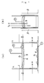
- Fig. 1a is a lateral sectional view showing main portions of a constitution of the purifying apparatus of the invention
- Fig.1b a front sectional view showing the same.
- Apositive electrode plate is constituted as one in which a conductive porous metal (A) such as titanium for instance is made a base plate and to which there is integrally applied an oxide electrode or a platinum electrode (B), which consists of an oxide such as titanium oxide, ruthenium oxide, cobalt oxide, nickel oxide or tin oxide or platinum.
- Plural electrodes (B) are disposed orthogonally to a flowing direction ( ⁇ ) of the flowing water.
- the positive electrode mentioned above is adapted such that it floats by air floats (F) utilizing buoyancies of air reservoirs disposed back and forth in the flowing direction ( ⁇ ), and moves up and down by movable crowns (h).
- the movable crown (h) is adapted such that its position is detected by a differential transformer (I).
- a seal plate (D) as means for gas seal is integrally arranged on a back face of the porous metal (A) as the base plate constituting the positive electrode plate, a gas reservoir (C) is mounted at a downstream side of the positive electrode, and a gas generated in a surface of the electrode (B) is collected into the gas reservoir (C) directly or after entering into the porous metal (A) and discharged by a gas collecting pump (P).
- the electrode (B) has a concave shape in section, thereby making it possible to easily collect the generated gas.
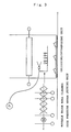
- a turbulent flow generating plate (G) is placed on a surface of a negative electrode plate (E) in order to maintain the turbulent flow, and thus it is adapted such that an oxidation/decomposition efficiency is enhanced by making it easy to generate the turbulent flow.
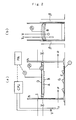
- the differential transformer provided in the movable crowns (h) as vertically moving means, it is adapted such that a voltage between the positive electrode plate and the negative electrode plate is changed between 200 V/cm and 10 KV/cm.
- a turbidimeter (Tu) as a concentration detector is provided in front of the flow, and an electric current is changed between 1 mA and 100 mA in compliance with the concentration.
- a flow velocity meter (V) is arranged in a similar manner and, from the flow velocity, a frequency is changed between 10 kHz and 150 kHz.
- Fig.2a and Fig.2b it is adapted such that positions of plus and minus are detected by the differential transformer (I) , the flow rate is detected by the flow velocity meter (V) , an SS amount is detected by the turbidimeter (Tu), a control unit (CPU) and an electric field generating unit (PA) are used, and these are made possible to perform controls of a voltage, a frequency, a pulse timing and a duty ratio by digital controls always as an optimum electric field treatment.
- a control unit CPU
- PA electric field generating unit
- the purifying apparatus is disposed within a width between side walls ( ⁇ ) such as concrete. It is practically desirable to dispose it in this manner.
- a suitable one there is shown one having a structure in which plural turbulent flow generating plates (G) each having a metal made protrusion are placed on the negative electrode plate (E) such that the water flow forms the turbulent flow with its height being limited to 10 - 15% of a distance between the electrode plates.
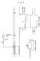
- a catalyst (d) by mixing the gas in a gas mixing unit (C) with hydrogen generated by an electrolysis of the water or hydrogen supplied from an H2 bomb (B), thereby intending to prevent the noxious gas from generating.
- the SS is sedimented by, for example, a high electromagnetic treatment, and the phosphorous and the SS in the polluted water can be eliminated in 80 - 90% by means of gravity-sedimenting them by providing in a downstream side a sedimentation tank through a bypass system by a pump or a direct system and returning a supernatant liquid to the original river (Fig.5).
- concentrations of the generated gasses are as shown in Table 3, and the gas after having been catalyst-treated by means of nickel and copper by a hydrogen addition was decreased in its noxious gasses, and their contents were in the order of traces.
- Generated gas After H 2 -treatment CO 2 50 - 60% 50 - 60% O 2 1 - 2% 100 - 300 ppm CO 0.1 - 0.2 10 - 20 ppm N 2 50 - 60% 50 - 60% NOx 300 ppm 10 ppm, SOx 0.01 - 0.02% 3 - 5%
- a life waste water (sewage) in Tsukuba-City was treated.
- the positive electrode plate there was used one in which a TiO2 particles sol was partially applied to a surface of porous ceramics having a porosity of 30% such that its thickness became 2 - 3 mm, the ceramics is sintered at 500 - 600°C after being dried, and the applied portion was made an electrode face.
- the gas generated by the decomposition was caused to pass through the air and thereafter collected.
- the effective elimination of the water pollution substances such as nitrogen and phosphorous which have hitherto been difficult to be eliminated becomes possible, so that it is made possible to perform the purification of the flow such as river with a high efficiency.
Landscapes
- Chemical & Material Sciences (AREA)
- Life Sciences & Earth Sciences (AREA)
- Engineering & Computer Science (AREA)
- Polymers & Plastics (AREA)
- Electrochemistry (AREA)
- Health & Medical Sciences (AREA)
- Botany (AREA)
- Food Science & Technology (AREA)
- Agronomy & Crop Science (AREA)
- Chemical Kinetics & Catalysis (AREA)
- Nutrition Science (AREA)
- General Chemical & Material Sciences (AREA)
- Hydrology & Water Resources (AREA)
- Environmental & Geological Engineering (AREA)
- Water Supply & Treatment (AREA)
- Organic Chemistry (AREA)
- Water Treatment By Electricity Or Magnetism (AREA)
- Physical Water Treatments (AREA)
Abstract
Description
| Original water | Treated water | |
| CODCT | 45-50 | 1-2 |
| T-N | 20-30 | 2-3 |
| NH3-N | 18-25 | 1-2 |
| NO3-N | 3-5 | 0.1-0.2 |
| T-P | 3-5 | 0.1-0.2 |
| SS | 40-45 | 5-10 |
| unit:mg/l |
| Voltage | 4kV -10kV |
| Electric current | 2 - 10mA |
| Frequency | 50 - 75kHz |
| Water depth | 10cm |
| Electrode (plus) | Titanium oxide (porous titanium base plate) |
| Electrode (minus) | SUS (stainless plate) |
| Generated gas | After H2-treatment | |
| CO2 | 50 - 60% | 50 - 60% |
| O2 | 1 - 2% | 100 - 300 ppm |
| CO | 0.1 - 0.2 | 10 - 20 ppm |
| N2 | 50 - 60% | 50 - 60% |
| NOx | 300 | 10 ppm, |
| SOx | 0.01 - 0.02% | 3 - 5% |
| Flow rate (m3/hr) | TOC (mg/L) | T•N (mg/L) | T•p (mg/L) | SS (mg/L) | |
| 0.60 | Original water | 13.2±5.0 | 10.3±3.8 | 1.0±0.5 | 30±8 |
| Treated water | 3.0±1.0 | 1.5±0.5 | 0.04±0.01 | 2±1 | |
| 1.23 | Original water | 12.5±5.0 | 10.1±3.5 | 1.2±0.6 | 32±8 |
| Treated water | 2.5±1.0 | 1.8±0.8 | 0.08±0.02 | 3±1.5 | |
| Section: 50cm x 75cm Water depth: 30cm Normal pressure: 5kv, 10kHz, Duty ratio: 5% Positive electrode: TiO2 Negative electrode: Ti (Thickness 3mm) |
Claims (25)
- A purifying apparatus for flowing water in which a negative electrode plate is disposed on a flowing water bed and a positive electrode plate is disposed in an upper face oppositely to the negative electrode plate, characterized in that the positive electrode plate is adapted so as to be dipped below a water surface of the flowing water with floats being disposed at least any of front/back and left/right of the positive electrode plate in a flowing direction of the flowing water, in the positive electrode plate there is arranged means for disposing it to an opposed upper face position with respect to the negative electrode plate, and the positive electrode plate and the negative electrode plate are provided with an electric field generating means, so that water pollution substances contained in the flowing water are oxidized and decomposed by a generation of high electric field pulses.
- A purifying apparatus of claim 1, wherein in the positive electrode plate there is arranged means for vertically moving it.
- A purifying apparatus of claim 1 or 2, wherein there is arranged gas collecting means.
- A purifying apparatus of claim 3, wherein the gas collecting means is arranged in a rear portion of the positive electrode plate in the flowing direction of the flowing water.
- A purifying apparatus of claim 3 or 4, wherein the gas collecting means is arranged in a positive electrode plate back face upper portion which is reverse to an opposing face of the negative electrode plate.
- A purifying apparatus of any of claims 1 to 5, wherein the positive electrode plate has at least one of metal or metal oxide.
- A purifying apparatus of any one of claims 1 to 6, wherein the positive electrode plate is a metal, a ceramics or a resin, or a composite body consisting of more than two of the formers.
- A purifying apparatus of any one of claims 1 to 7, wherein the positive electrode plate is a porous plate.
- A purifying apparatus of any one of claims 6 to 8, wherein a positive electrode substance is at least one of titanium oxide, ruthenium oxide, cobalt oxide, nickel oxide, tin oxide and platinum.
- A purifying apparatus of any one of claims 7 to 9, wherein a plate of porous titanium, porous ceramics or stainless is made a base plate in the positive electrode plate.
- A purifying apparatus of any one of claims 6 to 10, wherein plural positive electrode face portions each having a positive electrode substance are arranged in the positive electrode plate.
- A purifying apparatus of any one of claims 1 to 11, wherein the positive electrode plate has a concave curved face opposite to the negative electrode plate.
- A purifying apparatus of any one of claims 1 to 12, wherein gas seal means is arranged in the positive electrode plate.
- A purifying apparatus of claim 13, wherein the gas seal means is arranged in a positive electrode plate back face which is reverse to the opposing face of the negative electrode plate.
- A purifying apparatus of any one of claims 2 to 14, wherein the positive electrode plate is adapted by the vertically moving means such that its dipped depth from the water surface is 1/5 - 1/10 of a water depth.
- A purifying apparatus of any one of claims 1 to 15, wherein a stainless plate or a metal plate to which a platinum foil coating has been applied is made the negative electrode plate.
- A purifying apparatus of any one of claims 2 to 16, wherein the means for vertically moving the positive electrode plate in a gravity direction is provided with a differential transformer, thereby constituting a control mechanism for changing a voltage between faces of the positive electrode plate and the negative electrode plate between 200 V/cm and 10 KV/cm.
- A purifying apparatus of any one of claims 1 to 17, wherein a turbidity detector is provided in front of a flowing water flow with respect to the positive electrode plate, thereby constituting an automatic control mechanism for changing an electric current value between 1 mA and 100 mA in compliance with the turbidity.
- A purifying apparatus of any one of claims 1 to 18, wherein a flow velocity meter is installed in the flowing water, thereby constituting an automatic control mechanism for changing a frequency between 10 kHz and 150 kHz from the flow velocity.
- A purifying apparatus of any one of claims 1 to 19, wherein a plurality of metal made protrusions are provided on the electrode plate of at least one of the positive electrode plate and the negative electrode plate, and a structure by which the flowing water forms a turbulent flow is obtained by causing a height of the protrusion to be 10 - 15% of a distance between the positive electrode plate and the negative electrode plate.
- A purifying apparatus of any one of claims 1 to 20, wherein there is provided a mechanism for manually or automatically cleaning a surface portion or surface portions of one or both of the positive electrode plate and the negative electrode plate by a high pressure water jetting unit or a roll brush.
- A purifying apparatus of any one of claims 3 to 21, wherein the gas collecting means has a gas reservoir, and there is provided a mechanism for sucking a gas in the gas reservoir by a water pressure, a suction pump or a blower, mixing the gas with hydrogen gas by an electrolysis or hydrogen gas by a hydrogen bomb, and reducing the gas to N2 and water by a catalyst.
- A purifying apparatus of any one of claims 1 to 22, wherein there is adjunctively provided, together with a unit for collecting and separating sediments generated by a suspension, a sedimentation tank decreasing the flow velocity in a rear of the unit in the flowing direction, or there is adjunctively provided a system in which a water flow is dammed and a part thereof is pumped up by a pump so as to be bypassed from the water flow and the sediments are sedimented in a gravity sedimentation tank, and a supernatant liquid is returned to an original river.
- A purifying apparatus of any one of claims 2 to 23, wherein there is provided an emergency evacuation unit for lifting up the vertically moving means in an upward direction by an oil pressure or an electric motor at an abnormal flow rate time such as a flood.
- A purifying method for flowing water, characterized in that the flowing water is treated by using an apparatus of any of claims 1 to 24.
Applications Claiming Priority (3)
| Application Number | Priority Date | Filing Date | Title |
|---|---|---|---|
| JP11091199 | 1999-04-19 | ||
| JP11091199 | 1999-04-19 | ||
| PCT/JP2000/002541 WO2000063123A1 (en) | 1999-04-19 | 2000-04-19 | Purifier |
Publications (3)
| Publication Number | Publication Date |
|---|---|
| EP1112966A1 true EP1112966A1 (en) | 2001-07-04 |
| EP1112966A4 EP1112966A4 (en) | 2001-11-07 |
| EP1112966B1 EP1112966B1 (en) | 2007-09-26 |
Family
ID=14547775
Family Applications (1)
| Application Number | Title | Priority Date | Filing Date |
|---|---|---|---|
| EP00917360A Expired - Lifetime EP1112966B1 (en) | 1999-04-19 | 2000-04-19 | Water treatment method |
Country Status (5)
| Country | Link |
|---|---|
| US (1) | US6712947B1 (en) |
| EP (1) | EP1112966B1 (en) |
| CN (1) | CN1151082C (en) |
| DE (1) | DE60036529T2 (en) |
| WO (1) | WO2000063123A1 (en) |
Cited By (2)
| Publication number | Priority date | Publication date | Assignee | Title |
|---|---|---|---|---|
| CN101380041B (en) * | 2008-10-16 | 2010-11-03 | 中国农业大学 | Method for reducing organophosphorus pesticide in soymilk |
| CN108996618A (en) * | 2018-08-08 | 2018-12-14 | 上海荣德环保工程有限公司 | A kind of novel floating electro-chemical water processing equipment |
Families Citing this family (4)
| Publication number | Priority date | Publication date | Assignee | Title |
|---|---|---|---|---|
| EP1201609A4 (en) * | 1999-05-06 | 2006-12-13 | Japan Science & Tech Agency | APPARATUS WHICH CAN DETURN BY OXIDATION A NOCIVE SUBSTANCE FOR TRACES |
| US20070272550A1 (en) * | 2006-05-24 | 2007-11-29 | Advanced Desalination Inc. | Total solution for water treatments |
| KR102313539B1 (en) * | 2018-11-21 | 2021-10-15 | 이연주 | Sterilizing electrode and method thereof and sterilizer using same |
| CN110146346B (en) * | 2019-06-18 | 2021-07-06 | 青岛科技大学 | A sampling assembly for the detection of hydrogen produced by electrocatalytic decomposition of water |
Family Cites Families (13)
| Publication number | Priority date | Publication date | Assignee | Title |
|---|---|---|---|---|
| DE2419191A1 (en) * | 1974-04-20 | 1975-11-06 | Messerschmitt Boelkow Blohm | Stagnant water oxygen enrichment - by planar electrodes suspended from float and connected to power supply |
| US4048383A (en) * | 1976-02-09 | 1977-09-13 | Battelle Memorial Institute | Combination cell |
| US4808304A (en) * | 1983-10-19 | 1989-02-28 | Deal Troy M | Apparatus for the dewatering of phosphate slimes |
| DE4137281C2 (en) * | 1991-11-13 | 1993-10-21 | Karl Fuerst | Process and device for controlling algae in fresh water |
| IT1266557B1 (en) * | 1993-07-21 | 1997-01-09 | Arturo Guerini | PROCEDURE AND EQUIPMENT FOR TREATMENT OF WET LIQUID IN PRINTING MACHINES, ESPECIALLY FOR |
| US5464513A (en) * | 1994-01-11 | 1995-11-07 | Scientific Utilization, Inc. | Method and apparatus for water decontamination using electrical discharge |
| US5569809A (en) * | 1995-07-03 | 1996-10-29 | General Electric Company | Method for destruction of chlorinated hydrocarbons |
| JP2911393B2 (en) * | 1995-07-25 | 1999-06-23 | 日本テクノ株式会社 | Method and apparatus for producing fertilizer aqueous solution from electroless nickel plating wastewater |
| DE19534736A1 (en) * | 1995-09-19 | 1997-03-20 | Harry Prof Dr Med Rosin | Electrolytic cell with opt. ultrasound unit |
| WO1999044057A1 (en) * | 1996-08-26 | 1999-09-02 | Microvolt Oy | Device and method for measuring the action potential of aquatic organisms |
| JPH11347556A (en) * | 1998-06-10 | 1999-12-21 | Shikishima Kiki Kk | Electrochemical water treatment apparatus and method |
| JP4105315B2 (en) * | 1998-12-24 | 2008-06-25 | 株式会社神戸製鋼所 | Discharge treatment device |
| EP1161400B1 (en) * | 1999-03-15 | 2004-06-16 | Daishin Design Corporation | Method and apparatus for treatment of organic matter-containing wastewater |
-
2000
- 2000-04-19 DE DE60036529T patent/DE60036529T2/en not_active Expired - Fee Related
- 2000-04-19 EP EP00917360A patent/EP1112966B1/en not_active Expired - Lifetime
- 2000-04-19 WO PCT/JP2000/002541 patent/WO2000063123A1/en not_active Ceased
- 2000-04-19 CN CNB008006199A patent/CN1151082C/en not_active Expired - Fee Related
- 2000-04-19 US US09/719,854 patent/US6712947B1/en not_active Expired - Fee Related
Cited By (2)
| Publication number | Priority date | Publication date | Assignee | Title |
|---|---|---|---|---|
| CN101380041B (en) * | 2008-10-16 | 2010-11-03 | 中国农业大学 | Method for reducing organophosphorus pesticide in soymilk |
| CN108996618A (en) * | 2018-08-08 | 2018-12-14 | 上海荣德环保工程有限公司 | A kind of novel floating electro-chemical water processing equipment |
Also Published As
| Publication number | Publication date |
|---|---|
| CN1302278A (en) | 2001-07-04 |
| DE60036529T2 (en) | 2008-06-19 |
| DE60036529D1 (en) | 2007-11-08 |
| WO2000063123A8 (en) | 2001-02-15 |
| WO2000063123A1 (en) | 2000-10-26 |
| EP1112966B1 (en) | 2007-09-26 |
| CN1151082C (en) | 2004-05-26 |
| US6712947B1 (en) | 2004-03-30 |
| EP1112966A4 (en) | 2001-11-07 |
Similar Documents
| Publication | Publication Date | Title |
|---|---|---|
| US4908109A (en) | Electrolytic purification system utilizing rapid reverse current plating electrodes | |
| US3756933A (en) | Method of purifying sewage efluent and apparatus therefor | |
| EP3848332A1 (en) | Plasma denitriding device and use method thereof | |
| US6878268B2 (en) | Apparatus for purification of water | |
| CN207375910U (en) | A kind of processing system of landfill leachate | |
| EP1112966B1 (en) | Water treatment method | |
| CN110655228A (en) | Wastewater treatment process and system | |
| CN108585123A (en) | A filter type electrochemical reactor, water treatment device and water treatment method | |
| CN110451697A (en) | Salt-containing organic wastewater electrocatalytic oxidation coupling pretreatment method and device | |
| CN216863881U (en) | Laboratory waste water low-voltage electric flocculation oxidation reaction equipment | |
| CN110683617A (en) | Differential control based paired wastewater electrolysis treatment method | |
| EP0668244A1 (en) | Effluent treatment involving electroflotation | |
| JP4428804B2 (en) | Purification device | |
| CN107840441B (en) | Intelligent switching type ozone/electric filtration synergistic water treatment equipment and method for performing water treatment by using same | |
| KR100319022B1 (en) | Wastewater Treatment System Using Electrolytic Injury Method | |
| CN113697966A (en) | Treatment system and treatment method for mariculture wastewater | |
| CN209890411U (en) | Integrated refuse transfer station percolate premixing electrolysis air-flotation pretreatment device | |
| CN212504150U (en) | An electrocatalytic oxidation device and wastewater treatment system | |
| CN117843199B (en) | Centrifugal adsorption treatment equipment for heavy metal sewage | |
| CN109775817A (en) | A kind of electrochemistry ammonia nitrogen digestion instrument and digestion procedure | |
| CN206069474U (en) | A kind of oily waste water electric flocculation depth air-flotation system | |
| CN110204139A (en) | A kind of composite waste of electrolytic plating processing system using multistage electrochemical process technology | |
| JP3117064B2 (en) | Method and apparatus for treating oxidized nitrogen-containing water | |
| EP1470081B1 (en) | Device for electrolytic purification of liquids | |
| US20130175210A1 (en) | Odor treatment device for septic tanks |
Legal Events
| Date | Code | Title | Description |
|---|---|---|---|
| PUAI | Public reference made under article 153(3) epc to a published international application that has entered the european phase |
Free format text: ORIGINAL CODE: 0009012 |
|
| 17P | Request for examination filed |
Effective date: 20010119 |
|
| AK | Designated contracting states |
Kind code of ref document: A1 Designated state(s): AT BE CH CY DE DK ES FI FR GB GR IE IT LI LU MC NL PT SE |
|
| A4 | Supplementary search report drawn up and despatched |
Effective date: 20010921 |
|
| AK | Designated contracting states |
Kind code of ref document: A4 Designated state(s): AT BE CH CY DE DK ES FI FR GB GR IE IT LI LU MC NL PT SE |
|
| 17Q | First examination report despatched |
Effective date: 20040414 |
|
| RBV | Designated contracting states (corrected) |
Designated state(s): DE FR GB |
|
| RAP1 | Party data changed (applicant data changed or rights of an application transferred) |
Owner name: JAPAN SCIENCE AND TECHNOLOGY AGENCY |
|
| RTI1 | Title (correction) |
Free format text: WATER TREATMENT APPARATUS |
|
| RTI1 | Title (correction) |
Free format text: WATER TREATMENT METHOD |
|
| GRAP | Despatch of communication of intention to grant a patent |
Free format text: ORIGINAL CODE: EPIDOSNIGR1 |
|
| GRAS | Grant fee paid |
Free format text: ORIGINAL CODE: EPIDOSNIGR3 |
|
| GRAA | (expected) grant |
Free format text: ORIGINAL CODE: 0009210 |
|
| AK | Designated contracting states |
Kind code of ref document: B1 Designated state(s): DE FR GB |
|
| REG | Reference to a national code |
Ref country code: GB Ref legal event code: FG4D |
|
| REF | Corresponds to: |
Ref document number: 60036529 Country of ref document: DE Date of ref document: 20071108 Kind code of ref document: P |
|
| ET | Fr: translation filed | ||
| PGFP | Annual fee paid to national office [announced via postgrant information from national office to epo] |
Ref country code: DE Payment date: 20080429 Year of fee payment: 9 |
|
| PLBE | No opposition filed within time limit |
Free format text: ORIGINAL CODE: 0009261 |
|
| STAA | Information on the status of an ep patent application or granted ep patent |
Free format text: STATUS: NO OPPOSITION FILED WITHIN TIME LIMIT |
|
| 26N | No opposition filed |
Effective date: 20080627 |
|
| PGFP | Annual fee paid to national office [announced via postgrant information from national office to epo] |
Ref country code: FR Payment date: 20080409 Year of fee payment: 9 |
|
| PGFP | Annual fee paid to national office [announced via postgrant information from national office to epo] |
Ref country code: GB Payment date: 20080404 Year of fee payment: 9 |
|
| GBPC | Gb: european patent ceased through non-payment of renewal fee |
Effective date: 20090419 |
|
| REG | Reference to a national code |
Ref country code: FR Ref legal event code: ST Effective date: 20091231 |
|
| PG25 | Lapsed in a contracting state [announced via postgrant information from national office to epo] |
Ref country code: DE Free format text: LAPSE BECAUSE OF NON-PAYMENT OF DUE FEES Effective date: 20091103 |
|
| PG25 | Lapsed in a contracting state [announced via postgrant information from national office to epo] |
Ref country code: GB Free format text: LAPSE BECAUSE OF NON-PAYMENT OF DUE FEES Effective date: 20090419 Ref country code: FR Free format text: LAPSE BECAUSE OF NON-PAYMENT OF DUE FEES Effective date: 20091222 |