EP1112896A1 - Power generation system for a dual-voltage - Google Patents
Power generation system for a dual-voltage Download PDFInfo
- Publication number
- EP1112896A1 EP1112896A1 EP00403549A EP00403549A EP1112896A1 EP 1112896 A1 EP1112896 A1 EP 1112896A1 EP 00403549 A EP00403549 A EP 00403549A EP 00403549 A EP00403549 A EP 00403549A EP 1112896 A1 EP1112896 A1 EP 1112896A1
- Authority
- EP
- European Patent Office
- Prior art keywords
- voltage
- network
- sub
- alternator
- generation system
- Prior art date
- Legal status (The legal status is an assumption and is not a legal conclusion. Google has not performed a legal analysis and makes no representation as to the accuracy of the status listed.)
- Granted
Links
Images


Classifications
-
- H—ELECTRICITY
- H02—GENERATION; CONVERSION OR DISTRIBUTION OF ELECTRIC POWER
- H02J—CIRCUIT ARRANGEMENTS OR SYSTEMS FOR SUPPLYING OR DISTRIBUTING ELECTRIC POWER; SYSTEMS FOR STORING ELECTRIC ENERGY
- H02J7/00—Circuit arrangements for charging or depolarising batteries or for supplying loads from batteries
- H02J7/14—Circuit arrangements for charging or depolarising batteries or for supplying loads from batteries for charging batteries from dynamo-electric generators driven at varying speed, e.g. on vehicle
- H02J7/1423—Circuit arrangements for charging or depolarising batteries or for supplying loads from batteries for charging batteries from dynamo-electric generators driven at varying speed, e.g. on vehicle with multiple batteries
-
- B—PERFORMING OPERATIONS; TRANSPORTING
- B60—VEHICLES IN GENERAL
- B60R—VEHICLES, VEHICLE FITTINGS, OR VEHICLE PARTS, NOT OTHERWISE PROVIDED FOR
- B60R16/00—Electric or fluid circuits specially adapted for vehicles and not otherwise provided for; Arrangement of elements of electric or fluid circuits specially adapted for vehicles and not otherwise provided for
- B60R16/02—Electric or fluid circuits specially adapted for vehicles and not otherwise provided for; Arrangement of elements of electric or fluid circuits specially adapted for vehicles and not otherwise provided for electric constitutive elements
- B60R16/03—Electric or fluid circuits specially adapted for vehicles and not otherwise provided for; Arrangement of elements of electric or fluid circuits specially adapted for vehicles and not otherwise provided for electric constitutive elements for supply of electrical power to vehicle subsystems or for
-
- H—ELECTRICITY
- H02—GENERATION; CONVERSION OR DISTRIBUTION OF ELECTRIC POWER
- H02J—CIRCUIT ARRANGEMENTS OR SYSTEMS FOR SUPPLYING OR DISTRIBUTING ELECTRIC POWER; SYSTEMS FOR STORING ELECTRIC ENERGY
- H02J2310/00—The network for supplying or distributing electric power characterised by its spatial reach or by the load
- H02J2310/40—The network being an on-board power network, i.e. within a vehicle
- H02J2310/46—The network being an on-board power network, i.e. within a vehicle for ICE-powered road vehicles
-
- Y—GENERAL TAGGING OF NEW TECHNOLOGICAL DEVELOPMENTS; GENERAL TAGGING OF CROSS-SECTIONAL TECHNOLOGIES SPANNING OVER SEVERAL SECTIONS OF THE IPC; TECHNICAL SUBJECTS COVERED BY FORMER USPC CROSS-REFERENCE ART COLLECTIONS [XRACs] AND DIGESTS
- Y02—TECHNOLOGIES OR APPLICATIONS FOR MITIGATION OR ADAPTATION AGAINST CLIMATE CHANGE
- Y02T—CLIMATE CHANGE MITIGATION TECHNOLOGIES RELATED TO TRANSPORTATION
- Y02T10/00—Road transport of goods or passengers
- Y02T10/60—Other road transportation technologies with climate change mitigation effect
- Y02T10/70—Energy storage systems for electromobility, e.g. batteries
Definitions
- the invention relates to a system for generating power for an on-board dual voltage electrical network on a motor vehicle, intended to meet the increasing demand for electrical power within future vehicles, which will present new electrical functions designed to improve safety, like passenger comfort. Simultaneously, the invention must take into account the objectives of increasingly reduced fuel consumption, also aimed at reducing pollutant emissions.
- one solution is to replace the diodes of the rectification circuit by transistors to constitute an inverter.
- Another solution currently being considered by automakers is to increase the output voltage, in particular to triple the voltage current from the 14 Volt network to reach 42 Volts.
- This solution is advantageous because it allows the use of certain consumers who do not work with 42 Volts, improving the network distribution both in terms of relaying, fusiblage, the connection as the cable section which is then reduced, and the production extra energy.
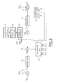
- This phase of cohabitation of the two sub-networks of different voltages suppose a configuration particular electrical production system of energy, an example of which is shown in the diagram functional of Figure 1. It comprises, driven by the vehicle engine 2 shaft, direct or via a reducer, an electrical machine 3, of the type alternator or alternator-starter, associated with a circuit rectification 4 made from one or more diode bridges according to the number of stator windings.
- an alternator-starter the rectification is carried out using transistors constituting a inverter.
- the machine thus straightened is connected by a share of elements 5 consumers in 42 Volts and on the other hand to a battery 6, which can be constituted of several storage elements 60, of tension between 30 and 48 Volts.
- a converter static 7 should lower the voltage from 42 Volts to one nominal voltage of 14 Volts, to ensure transfer of energy to the second network, which has a battery 8 of 12 Volts and powers the elements consumers 9 operating at this voltage.
- This architecture has many disadvantages, including the presence of this electronic converter, expensive, bulky - approximately 1.5 liters of volume depending on its power -, generating heat losses difficult to evacuate.
- the invention aims to overcome these drawbacks by offering an energy production system for dual voltage network without DC / DC voltage converter, can operate as alternator or alternator-starter and authorizing the transfer of energy from a from the two subnets to the other, in particular from 42 Volts around 14 Volts, but also so fully reversible.
- the object of the invention is a power generation system for a two-voltage electrical network, comprising an electrical machine of the three-phase alternator type whose stator phases are rectified to generate the desired power on the sub-network operating at a first voltage value U s , characterized in that the stator of the three-phase alternator is wound in a star so as to have a neutral point N to which the second sub-network operating is connected to a second voltage value U b less than the first, and in that it comprises electronic means for controlling and regulating the voltages U s and U b of the two sub-networks.
- the means for rectifying the stator phases of the three-phase alternator are constituted by a three-phase inverter comprising six switches H 1 to H 3 and L 1 to L 3 , of the type transistors, connected in series and in the same direction, in groups of two between earth and the highest voltage U s for each of the three phases of the stator, each of the six transistors being controlled by the electronic control circuit, which is intended in slaving the average value of the voltage of the three phases to a reference voltage making it possible to obtain the voltage U b at the input of the second lower voltage sub-network.
- the system further comprises two filtering means respectively arranged at the neutral point N at the input of the lower voltage sub-grid U b and at the output of the inverter at the input of the higher voltage sub-network U b s .
- the means for rectifying the stator phases of the three-phase alternator consist of a passive rectification bridge comprising six diodes d 1 to d 6 , mounted in groups of two, in series and in the same direction, between the ground and the highest voltage U s for each of the three phases of the stator and in that the electronic means for regulating the voltage U b of the second sub-network consist of a switch I 0 whose closure is controlled by a control circuit.
- the means for rectifying the stator phases of the three-phase alternator are constituted by a passive rectifying bridge comprising six diodes d 1 to d 6 , mounted in groups of two, in series and in the same direction, between the mass and the highest voltage U s for each of the three phases of the stator and in that the electronic means for regulating the voltage U b of the second sub-network are constituted by a linear or switching regulator.
- the power production system for a two-voltage electrical network comprises a three-phase electrical machine 20 of the alternator type, which can be synchronous with a wound rotor or with magnets, or even mixed wound and with magnets.
- the stator phases are rectified to generate the desired power on the first sub-network operating at a first voltage value U s .
- U s can also be an asynchronous alternator. It is wound in a star to the stator so as to present a neutral point N to which is connected the second sub-network operating at a second voltage value U b lower than the first voltage value U s .
- a three-phase inverter 21 which delivers a voltage U s , equal to 42 Volts in the particular case of a current motor vehicle, and which consists of six switches H 1 to H 3 and L 1 to L 3 . They are arranged in three arms of two switches each, mounted in series and in the same direction, one L i "low-side” between the ground and one of the phases and the other H i "high-side” between the phase and the higher voltage U s .
- These switches are MOSFET or IGBT or bipolar or other type transistors, whether or not associated with a reverse diode.
- control and regulation means 22 which receive instructions for regulating the voltages U s and U b of the two sub-networks, coming from a computer 99 establishing electronic strategies for managing the electrical energy of the network.
- control means 22 can also receive information on the position of the rotor relative to the stator from a position sensor 32.
- Two filtering means 23 and 24 can be respectively arranged at the entrance of each of the two subnets, i.e. at neutral point N, towards the 14 Volt subnet and at the output S of the regulation circuit, to the 42 Volt sub-network.
- These means are for example made up of capacities associated with inductors dimensioned to deliver filtered DC voltages remaining within tolerances allowed for the application, electromagnetic emission and susceptibility.
- These two subnets can each have one battery, referenced respectively 25 and 26, and supply consumers 27 and 28 operating 14 Volts and 42 Volts respectively.
- Voltage regulation on the 14 Volt sub-network, is obtained by adjusting the average value of the three phase voltages, i.e. by adjusting the three control signals of the three-phase machine delivered by the electronic circuit for controlling and regulating the voltages U s and U b of the two-voltage network.
- alternator or alternator-starter.
- the regulation of these two voltages is done according to a method of pulse width modulation of control signals of the transistors constituting the arm of the inverter, to generate on the three phases, three periodic waves, sinusoidal, trapezoidal, triangular for example, out of phase with 120 ° from each other.
- This process is applicable to three types of machine: synchronous wound rotor (SYRB), synchronous permanent magnet (SYAP) and asynchronous (ASY).
- the regulation is done according to a command process "full wave" of the synchronous rectification type, applicable only to synchronous rotor machines coil.
- the regulation of the upper voltage U s is carried out by two parameters: the adjustment of the amplitude of the setpoints of phase and the adjustment either of the excitation of the rotor in the case of a synchronous alternator with wound rotor, or of the slip of speed existing between the speed of the stator rotary field and the mechanical speed of rotation of the rotor in the case of a asynchronous alternator, ie of the phase shift between the stator magnetic field and the rotor flux in the case of a synchronous permanent magnet alternator.
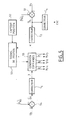
- FIG. 3 is a functional diagram of the electronic control means 22 of the inverter, ensuring the regulation of the two voltages U s and U b of the two-voltage network according to the invention.
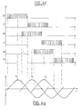
- means 33 generate the position signal, for example in the form of synchronization tops (FIG. 4 a ) which are sent to means 34 for developing a reference signal S ref , a sinusoid for example.
- These means 34 take into account the phase shift setpoints DEP or slip GLI, coming from the second corrector C 2 , to offset the synchronization tops of the position signal (FIG. 4b) from which the reference sinusoid S ref (FIG. 4 c ). To this is then applied a multiplicative coefficient C m , calculated by the correction circuit C 1 , to adjust the amplitude A of this sinusoid (FIG. 4 d ). This amplitude is imperatively less than U s , or 42 Volts, for reasons of safety of the passengers of the vehicle, so that its average is around 24 Volts.
- the lowest voltage U b is regulated by adjusting the average value of the setpoints of the three phases.
- This phase setpoint signal thus obtained is then transformed by a pulse width modulation method in means 37 for generating control pulses of the six transistors of the inverter 21, H i and L i , i varying from 1 to 3 ( Figure 4 f ).
- This control of the transistors of the inverter thus makes it possible to generate three periodic voltage waves, offset by 120 ° from one another, in the form of sinusoids in FIG. 4 g , at the level of the three phases P 1 to P 3 , authorizing continuous rotation of the alternator stator field.
- FIG. 5 a functional diagram of the electronic means of control of the inverter is shown in FIG. 5, in the case of a synchronous machine with a wound rotor, the regulation of the two voltages of the dual voltage network made by a "full wave” type control process synchronous rectification.
- Regulation of the upper voltage U s at the output of the inverter is carried out by two parameters: the adjustment of the excitation of the rotor on the one hand and the combined adjustment of the phase shift angle ⁇ and the angle of ⁇ opening of the inverter control signal pulses.
- differentiating means 51 calculate an error ⁇ s existing between the voltage U s measured at the input of the 42 Volt sub-network and a set value (U ' s ) c delivered by an external electronic computer, then send it to the first correcting means C 4 which will calculate the excitation EXC of the rotor.
- a rotor position sensor 52 relative to the stator or an auto-detection method according to the type of synchronous machine make it possible to develop a position signal, for example in the form of synchronization ticks (FIG. 6 a ) , in means 53, which will be offset by a phase shift angle ⁇ (FIG. 6 b ), calculated in second correcting means C 5 from the error ⁇ s previously found.
- Second differentiating means 54 calculate the error ⁇ b between the voltage U b measured at the terminals of the second sub-network and a set value (U ' b ) c delivered by the external computer.
- This error ⁇ b passes through correcting means C 6 which calculate the opening angle ⁇ , sent into means 55 for generating control pulses of the inverter, which moreover receive the synchronization tops offset by the angle ⁇ .
- FIG. 6 c represents the control signals in each of the six transistors of the inverter, each pair of high H i and low L i transistors being assigned to one of the three phases P i , i varying from 1 to 3, at the output of which three periodic voltage waves are generated, offset by 120 °.
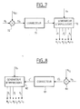
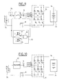
- Figure 7 is a block diagram of a structure voltage drop 42 Volts to voltage 14 Volts.
- the three arms of the inverter 21 are controlled at the same switching frequency and can be out of phase in order to decrease the residual rejection voltage on the two voltage networks.
- control means 22 of the inverter 21 comprise means 70 for generating control pulses of the transistors which receive, as input information, on the one hand the measured voltage U s at the terminals of the battery 26 of the first sub-network at 42 Volts and on the other hand the setpoint C calculated by correcting means 71 from the error ⁇ b resulting from the comparison between the measured voltage U b across the second sub-network and a reference value U b1 , carried out in comparison means 72.
- FIG. 8 is a block diagram of a static step-up converter.
- it is the voltage U b delivered by the battery 25 which is the input data from which the input voltage U s of the 42 Volt network will be regulated.
- This voltage U s is measured and compared in comparison means 80, to be controlled by a set point U C2 by determining a set point C 'in correcting means 81 from the error ⁇ s resulting from the comparison, in pulse width modulation.
- means 82 for generating control pulses send signals to the six transistors of the inverter 21.
- the means for rectifying the stator phases of the three-phase alternator 90 are of the passive type, consisting of a bridge 91 of six diodes d 1 to d 6 , or three groups of two diodes connected in series and in the same direction, for each of the three phases of the alternator, between the ground and the highest voltage U s of the two-voltage network, ie 42 Volts in the example chosen.
- the voltage U s of the sub-network connected at the output of this passive rectification bridge is regulated only by controlling the excitation of the rotor R of the alternator.
- the electronic means for regulating the voltage U b of the second sub-network are constituted by a switch I 0 , the closing of which is controlled by a control circuit 92.
- This circuit 92 compares the measured voltage U b on the one hand to a first threshold S OFF , in a comparator 93, to deliver a signal for controlling the opening of the switch I o , and on the other hand, to a second threshold S ON , in another comparator 94, to deliver a command signal to close it.
- These two control signals will alternately drive the switch I o , after passing through a logic flip-flop 95.
- a diode 96 can be placed in series with the switch I o to improve its operation and avoid the passage of a current from the sub-network at 14 Volts to the sub-network at 42 Volts.
- the regulation of the voltage U b of the second sub-network is ensured by a regulator 97, either of the linear type if the voltage at the neutral point N is close to the voltage U b at the input of the sub-network, either of the switching type if the voltage at the neutral point N is close to half of the voltage U s at the terminals of the first sub-network.
- the fact that the alternator produces energy directly at the 14 Volt subnet without intermediary allows obtaining a very good yield.
- the system is completely reversible, allowing the energy transfer from one of the two subnets towards the other. Thanks to the independence of the values of regulation of the two subnets it is possible to apply the invention to other voltage values, different from 14 and 42 Volts.
- the system according to the invention makes compatible the production of electrical energy with the use of all types of storage, such as a battery lead, lithium, nickel-cadmium or a high value capacitor for example.
- the system is reliable and has a duration of increased life due to minimization of components used to produce energy electric to the dual voltage network.
Abstract
Description
L'invention concerne un système de génération de puissance pour un réseau électrique bitension embarqué sur véhicule automobile, destiné à répondre à la demande croissante de puissance électrique dans les véhicules futurs, qui vont présenter de nouvelles fonctions électriques tendant à améliorer la sécurité, comme le confort des passagers. Simultanément, l'invention doit tenir compte des objectifs de consommation de carburant de plus en plus réduite, visant également à diminuer les émissions de polluants.The invention relates to a system for generating power for an on-board dual voltage electrical network on a motor vehicle, intended to meet the increasing demand for electrical power within future vehicles, which will present new electrical functions designed to improve safety, like passenger comfort. Simultaneously, the invention must take into account the objectives of increasingly reduced fuel consumption, also aimed at reducing pollutant emissions.
En effet, sur de nombreux projets de véhicules, les bilans électriques font apparaítre une demande croissante de puissance électrique, liée à l'apparition de ces nouvelles fonctions électriques qui sont par exemple le chauffage et la climatisation, les soupapes pilotées électromagnétiquement, la direction assistée électrique, le freinage électrique ... . Or, au-delà de 3 kiloWatts de production électrique, l'architecture globale du système de production de puissance doit être profondément modifiée, en particulier l'alternateur qui est entraíné par l'arbre tournant du moteur thermique pour fournir la tension de sortie utile. Les alternateurs classiques de type synchrone triphasé, dans leur configuration actuelle, c'est-à-dire avec un rotor à griffes bobiné, un refroidissement à air et un redressement à diodes pour une tension de sortie de 14 Volts, ne fonctionneront pas de façon optimale .Indeed, on many vehicle projects, the electrical balance sheets show a demand increasing electrical power, linked to the appearance of these new electrical functions which are by example heating and air conditioning, valves electromagnetically controlled, power steering electric, electric braking .... However, beyond 3 kiloWatts of electrical production, architecture overall power generation system must be profoundly modified, in particular the alternator which is driven by the rotating shaft of the heat engine to supply the useful output voltage. The conventional alternators of three-phase synchronous type, in their current configuration, that is to say with a wound claw rotor, air-cooled and diode rectification for an output voltage of 14 Volts, will not operate optimally.
Pour augmenter la puissance, différentes solutions ont été envisagées, comme le remplacement des griffes du rotor par des pôles saillants, l'ajout d'aimants au rotor ou le double bobinage au stator, l'amincissement des tôles, le refroidissement à eau, qui permettent d'augmenter sa puissance générée, sa densité et plus globalement ses performances.To increase the power, different solutions have considered, such as replacing the claws of the rotor by salient poles, the addition of magnets to the rotor or double stator winding, thinning sheets, water cooling, which allow increase its generated power, its density and more overall its performance.
Pour augmenter le rendement de production et tirer le meilleur parti des alternateurs, une solution consiste à remplacer les diodes du circuit de redressement par des transistors pour constituer un onduleur.To increase the production yield and draw the best use of alternators, one solution is to replace the diodes of the rectification circuit by transistors to constitute an inverter.
Une autre solution actuellement envisagée par les constructeurs automobiles consiste à augmenter la tension de sortie, en particulier à tripler la tension actuelle du réseau de 14 Volts pour atteindre 42 Volts. Cette solution est avantageuse car elle permet l'utilisation de certains consommateurs qui ne fonctionnent qu'avec 42 Volts, l'amélioration du réseau de distribution tant en ce qui concerne le relayage, le fusiblage, la connectique que la section des câbles électriques qui est alors réduite, et la production d'énergie supplémentaire.Another solution currently being considered by automakers is to increase the output voltage, in particular to triple the voltage current from the 14 Volt network to reach 42 Volts. This solution is advantageous because it allows the use of certain consumers who do not work with 42 Volts, improving the network distribution both in terms of relaying, fusiblage, the connection as the cable section which is then reduced, and the production extra energy.
Cependant, l'augmentation de la tension de sortie de l'alternateur doit rester compatible avec le standard actuel de tension du réseau de bord, soit 14 Volts, car il n'est pas envisageable de le remplacer brutalement et complètement par un réseau à 42 Volts, pour des raisons industrielles, techniques et économiques. Il faut donc envisager une phase de cohabitation des deux sous-réseaux d'alimentation électrique à 14 et 42 Volts au sein d'un même véhicule, même s'il faut prévoir l'évolution prochaine de certains circuits consommateurs du sous-réseau 14 Volts vers le sous-réseau 42 Volts. However, increasing the output voltage of the alternator must remain compatible with the standard current of the on-board network voltage, i.e. 14 Volts, because it is not possible to replace it suddenly and completely by a 42 Volt network, for industrial, technical and economic reasons. he must therefore consider a phase of cohabitation of the two 14 and 42 Volt power supply sub-networks in the same vehicle, even if you have to plan the next evolution of some circuits consumers from the 14 Volt subnet to the subnet 42 Volts.
Cette phase de cohabitation des deux sous-réseaux de
tensions différentes suppose une configuration
électrique particulière du système de production
d'énergie, dont un exemple est représenté sur le schéma
fonctionnel de la figure 1. Il comporte, entraínée par
l'arbre du moteur thermique 2 du véhicule, en direct ou
via un réducteur, une machine électrique 3, de type
alternateur ou alterno-démarreur, associée à un circuit
de redressement 4 réalisé à partir d'un ou plusieurs
ponts de diodes selon le nombre de bobinage du stator.
Dans le cas d'un alterno-démarreur, le redressement
s'effectue à l'aide de transistors constituant un
onduleur. La machine ainsi redressée est reliée d'une
part à des éléments 5 consommateurs en 42 Volts et
d'autre part à une batterie 6, pouvant être constituée
de plusieurs éléments de stockage 60, de tension
comprise entre 30 et 48 Volts. Un convertisseur
statique 7 doit abaisser la tension de 42 Volts à une
tension nominale de 14 Volts, pour assurer le transfert
d'énergie vers le deuxième réseau, qui comporte une
batterie 8 de 12 Volts et alimente les éléments
consommateurs 9 fonctionnant à cette tension.This phase of cohabitation of the two sub-networks of
different voltages suppose a configuration
particular electrical production system
of energy, an example of which is shown in the diagram
functional of Figure 1. It comprises, driven by
the
Cette architecture présente de nombreux inconvénients, dont la présence de ce convertisseur électronique, coûteux, encombrant - environ 1,5 litre de volume selon sa puisance -, générant des pertes thermiques difficiles à évacuer.This architecture has many disadvantages, including the presence of this electronic converter, expensive, bulky - approximately 1.5 liters of volume depending on its power -, generating heat losses difficult to evacuate.
De plus, la structure série entre l'alternateur et le réseau à 14 Volts aboutit à un rendement global limité par les rendements successifs des étages de conversion. On peut ajouter un coût global très supérieur à celui d'une architecture classique par alternateur sur réseau unique, à cause de l'ajout d'un convertisseur abaisseur de tension.In addition, the series structure between the alternator and the 14 Volt network results in limited overall performance by the successive yields of the conversion stages. We can add an overall cost much higher than that of a conventional architecture by alternator on the network unique, due to the addition of a buck converter Of voltage.
L'invention vise à pallier ces inconvénients en proposant un système de production d'énergie pour réseau bitension sans convertisseur DC/DC de tension, pouvant fonctionner en alternateur ou en alterno-démarreur et autorisant le transfert de l'énergie d'un des deux sous-réseaux vers l'autre, notamment du 42 Volts vers le 14 Volts, mais également de façon totalement réversible.The invention aims to overcome these drawbacks by offering an energy production system for dual voltage network without DC / DC voltage converter, can operate as alternator or alternator-starter and authorizing the transfer of energy from a from the two subnets to the other, in particular from 42 Volts around 14 Volts, but also so fully reversible.
Pour cela, l'objet de l'invention est un système de
génération de puissance pour un réseau électrique
bitension, comprenant une machine électrique de type
alternateur triphasé dont les phases statoriques sont
redressées pour générer la puissance souhaitée sur le
sous-réseau fonctionnant à une première valeur de
tension Us, caractérisé en ce que le stator de
l'alternateur triphasé est bobiné en étoile de façon à
présenter un point neutre N auquel est relié le second
sous-réseau fonctionnant à une deuxième valeur de
tension Ub inférieure à la première,
et en ce qu'il comporte des moyens électroniques de
commande et de régulation des tensions Us et Ub des
deux sous-réseaux.For this, the object of the invention is a power generation system for a two-voltage electrical network, comprising an electrical machine of the three-phase alternator type whose stator phases are rectified to generate the desired power on the sub-network operating at a first voltage value U s , characterized in that the stator of the three-phase alternator is wound in a star so as to have a neutral point N to which the second sub-network operating is connected to a second voltage value U b less than the first,
and in that it comprises electronic means for controlling and regulating the voltages U s and U b of the two sub-networks.
Selon une autre caractéristique du système de génération de puissance selon l'invention, les moyens de redressement des phases statoriques de l'alternateur triphasé sont constitués par un onduleur triphasé comprenant six interrupteurs H1 à H3 et L1 à L3, de type transistors, montés en série et dans le même sens, par groupe de deux entre la masse et la tension Us la plus élevée pour chacune des trois phases du stator, chacun des six transistors étant piloté par le circuit électronique de commande, qui est destiné à asservir la valeur moyenne de la tension des trois phases à une tension de consigne permettant d'obtenir la tension Ub en entrée du second sous-réseau à plus basse tension. Selon une autre caractéristique, le système comporte de plus deux moyens de filtrage respectivement disposés au point neutre N en entrée du sous-réseau à plus basse tension Ub et en sortie de l'onduleur en entrée du sous-réseau à plus haute tension Us.According to another characteristic of the power generation system according to the invention, the means for rectifying the stator phases of the three-phase alternator are constituted by a three-phase inverter comprising six switches H 1 to H 3 and L 1 to L 3 , of the type transistors, connected in series and in the same direction, in groups of two between earth and the highest voltage U s for each of the three phases of the stator, each of the six transistors being controlled by the electronic control circuit, which is intended in slaving the average value of the voltage of the three phases to a reference voltage making it possible to obtain the voltage U b at the input of the second lower voltage sub-network. According to another characteristic, the system further comprises two filtering means respectively arranged at the neutral point N at the input of the lower voltage sub-grid U b and at the output of the inverter at the input of the higher voltage sub-network U b s .
Selon une autre caractéristique, le moyens de redressement des phases statoriques de l'alternateur triphasé sont constitués par un pont de redressement passif comprenant six diodes d1 à d6, montées par groupe de deux, en série et dans le même sens, entre la masse et la tension Us la plus élevée pour chacune des trois phases du stator et en ce que les moyens électroniques de régulation de la tension Ub du second sous-réseau sont constitués d'un interrupteur I0 dont la fermeture est pilotée par un circuit de commande.According to another characteristic, the means for rectifying the stator phases of the three-phase alternator consist of a passive rectification bridge comprising six diodes d 1 to d 6 , mounted in groups of two, in series and in the same direction, between the ground and the highest voltage U s for each of the three phases of the stator and in that the electronic means for regulating the voltage U b of the second sub-network consist of a switch I 0 whose closure is controlled by a control circuit.
Selon une autre caractéristique, les moyens de redressement des phases statoriques de l'alternateur triphasé sont constitués par un pont de redressement passif comprenant six diodes d1 à d6, montées par groupe de deux, en série et dans le même sens, entre la masse et la tension Us la plus élevée pour chacune des trois phases du stator et en ce que les moyens électroniques de régulation de la tension Ub du second sous-réseau sont constitués par un régulateur linéaire ou à découpage.According to another characteristic, the means for rectifying the stator phases of the three-phase alternator are constituted by a passive rectifying bridge comprising six diodes d 1 to d 6 , mounted in groups of two, in series and in the same direction, between the mass and the highest voltage U s for each of the three phases of the stator and in that the electronic means for regulating the voltage U b of the second sub-network are constituted by a linear or switching regulator.
D'autres caractéristiques et avantages de l'invention apparaítront à la lecture de la description d'un exemple de réalisation d'un système de production de puissance pour réseau bitension, illustrée par les figures suivantes qui sont, outre la figure 1, déjà décrite à propos de l'art antérieur :
- la figure 2 : un schéma fonctionnel d'un système de production de puissance selon l'invention ;
- les figures 3 et 5 : deux schémas fonctionnels de deux variantes d'un premier mode de réalisation des moyens électroniques de régulation du réseau bitension selon l'invention ;
- les figures 4a à 4g : les chronogrammes des signaux délivrés par les, différents éléments du régulateur selon la première variante du premier mode de réalisation de l'invention ;
- la figure 6a à 6c : les chronogrammes des signaux délivrés par les différents éléments du régulateur selon la deuxième variante du premier mode de réalisation de l'invention ;
- la figure 7 : un schéma fonctionnel d'un circuit abaisseur de tension ;
- la figure 8 : un schéma fonctionnel d'un circuit élévateur de tension ;
- les figures 9 et 10 : les schémas fonctionnels de deux variantes du deuxième mode de réalisation du régulateur du réseau bitension selon l'invention.
- Figure 2: a block diagram of a power generation system according to the invention;
- FIGS. 3 and 5: two functional diagrams of two variants of a first embodiment of the electronic means for regulating the two-voltage network according to the invention;
- FIGS. 4 a to 4 g : the timing diagrams of the signals delivered by the, different elements of the regulator according to the first variant of the first embodiment of the invention;
- FIG. 6 a to 6 c : the timing diagrams of the signals delivered by the different elements of the regulator according to the second variant of the first embodiment of the invention;
- Figure 7: a block diagram of a step-down circuit;
- Figure 8: a block diagram of a voltage booster circuit;
- Figures 9 and 10: the block diagrams of two variants of the second embodiment of the two-voltage network regulator according to the invention.
Selon un premier mode de réalisation représenté
schématiquement sur la figure 2, le système de
production de puissance pour un réseau électrique
bitension comprend une machine électrique triphasée 20
de type alternateur, qui peut être synchrone à rotor
bobiné ou à aimants ou bien encore mixte bobinée et à
aimants. Les phases statoriques sont redressées pour
générer la puissance souhaitée sur le premier sous-réseau
fonctionnant à une première valeur de tension
Us. Ce peut être aussi un alternateur asynchrone. Il
est bobiné en étoile au stator de façon à présenter un
point neutre N auquel est relié le second sous-réseau
fonctionnant à une deuxième valeur de tension Ub
inférieure à la première valeur de tension Us.According to a first embodiment shown diagrammatically in FIG. 2, the power production system for a two-voltage electrical network comprises a three-phase
Pour redresser le courant des phases statoriques de
l'alternateur, ces trois phases sont reliées à un
onduleur triphasé 21, qui délivre une tension Us, égale
à 42 Volts dans le cas particulier d'un véhicule
automobile actuel, et qui est constitué de six
interrupteurs H1 à H3 et L1 à L3. Ils sont disposés
selon trois bras de deux interrupteurs chacun, montés
en série et dans le même sens, l'un Li "low-side" entre
la masse et une des phases et l'autre Hi "high-side"
entre la phase et la tension supérieure Us. Ces
interrupteurs sont des transistors de type MOSFET ou
IGBT ou bipolaire ou autre, associés ou non à une diode
inverse. Ils sont pilotés par des moyens électroniques
de commande et de régulation 22 qui reçoivent des
consignes de régulation des tensions Us et Ub des deux
sous-réseaux, provenant d'un calculateur 99 établissant
des stratégies électroniques de gestion de l'énergie
électrique du réseau. Ces moyens de commande 22 peuvent
également recevoir une information sur la position du
rotor par rapport au stator de la part d'un capteur de
position 32.To rectify the current of the stator phases of the alternator, these three phases are connected to a three-
Deux moyens de filtrage 23 et 24 peuvent être
respectivement disposés à l'entrée de chacun des deux
sous-réseaux, soit au niveau du point neutre N, vers le
sous-réseau à 14 Volts et au niveau de la sortie S du
circuit de régulation, vers le sous-réseau à 42 Volts.
Ces moyens sont par exemple constitués de capacités
associées à des inductances dimensionnées pour délivrer
des tensions continues filtrées restant dans les
tolérances admises pour l'application, en matière
d'émission et de susceptibilité électromagnétique. Ces
deux sous-réseaux peuvent comporter chacun une
batterie, référencée respectivement 25 et 26, et
alimenter des consommateurs 27 et 28 fonctionnant
respectivement à 14 Volts et à 42 Volts.Two filtering means 23 and 24 can be
respectively arranged at the entrance of each of the two
subnets, i.e. at neutral point N, towards the
14 Volt subnet and at the output S of the
regulation circuit, to the 42 Volt sub-network.
These means are for example made up of capacities
associated with inductors dimensioned to deliver
filtered DC voltages remaining within
tolerances allowed for the application,
electromagnetic emission and susceptibility. These
two subnets can each have one
battery, referenced respectively 25 and 26, and
supply
Lorsque la machine électrique 20 est en mouvement, en
mode alternateur entraíné par le moteur du véhicule ou
en mode démarreur pour au contraire entraíner le
moteur, la liaison de son point neutre N au sous-réseau
à 14 Volts impose la polarisation moyenne des trois
phases du stator au même potentiel Ub de 14 Volts, dont
les impédances en mode continu sont équivalentes aux
résistances des enroulements.When the
La régulation de tension, sur le sous-réseau de 14 Volts, est obtenue par l'ajustement de la valeur moyenne des trois tensions de phase, c'est-à-dire par l'ajustement des trois signaux de pilotage de la machine triphasée délivrés par le circuit électronique de commande et de régulation des tensions Us et Ub du réseau bitension. Il existe deux procédés classiques de pilotage de cet alternateur, ou alterno-démarreur.Voltage regulation, on the 14 Volt sub-network, is obtained by adjusting the average value of the three phase voltages, i.e. by adjusting the three control signals of the three-phase machine delivered by the electronic circuit for controlling and regulating the voltages U s and U b of the two-voltage network. There are two conventional methods for controlling this alternator, or alternator-starter.
Selon une première variante de réalisation, la régulation de ces deux tensions se fait selon un procédé de modulation de largeur d'impulsion des signaux de commande des transistors constituant les bras de l'onduleur, pour générer sur les trois phases, trois ondes périodiques, de forme sinusoïdale, trapézoïdale, triangulaire par exemple, déphasées de 120° les unes des autres. Ce procédé est applicable aux trois types de machine : synchrone à rotor bobiné (SYRB), synchrone à aimant permanent (SYAP) et asynchrone (ASY).According to a first alternative embodiment, the regulation of these two voltages is done according to a method of pulse width modulation of control signals of the transistors constituting the arm of the inverter, to generate on the three phases, three periodic waves, sinusoidal, trapezoidal, triangular for example, out of phase with 120 ° from each other. This process is applicable to three types of machine: synchronous wound rotor (SYRB), synchronous permanent magnet (SYAP) and asynchronous (ASY).
Selon une deuxième variante de réalisation, la régulation se fait selon un procédé de commandes "pleine onde" du type redressement synchrone, applicable seulement aux machines synchrones à rotor bobiné.According to a second alternative embodiment, the regulation is done according to a command process "full wave" of the synchronous rectification type, applicable only to synchronous rotor machines coil.
Dans le cas des deux procédés, il faut asservir la tension moyenne Umoy des trois tensions statoriques, sur les trois points de sortie des phases P1, P2 et P3, à une tension de consigne nécessaire pour la régulation du réseau à 14 Volts.In the case of both processes, it is necessary to slave the mean voltage moy U three stator voltages on the three phases of output points P 1, P 2 and P 3 at a desired voltage necessary for controlling the network 14 volts.
Dans le cas de la première variante de réalisation utilisant un procédé de modulation de largeur d'impulsions, la régulation de la tension supérieure Us, égale notamment à 42 Volts, est réalisée par deux paramètres : le réglage de l'amplitude des consignes de phase et le réglage soit de l'excitation du rotor dans le cas d'un alternateur synchrone à rotor bobiné, soit du glissement de vitesse existant entre la vitesse du champ tournant statorique et la vitesse de rotation mécanique du rotor dans le cas d'un alternateur asynchrone, soit du déphasage entre le champ magnétique statorique et le flux rotorique dans le cas d'un alternateur synchrone à aimant permanent.In the case of the first alternative embodiment using a pulse width modulation method, the regulation of the upper voltage U s , equal in particular to 42 Volts, is carried out by two parameters: the adjustment of the amplitude of the setpoints of phase and the adjustment either of the excitation of the rotor in the case of a synchronous alternator with wound rotor, or of the slip of speed existing between the speed of the stator rotary field and the mechanical speed of rotation of the rotor in the case of a asynchronous alternator, ie of the phase shift between the stator magnetic field and the rotor flux in the case of a synchronous permanent magnet alternator.
La figure 3 est un schéma fonctionnel des moyens électroniques de commande 22 de l'onduleur, assurant la régulation des deux tensions Us et Ub du réseau bitension selon l'invention. FIG. 3 is a functional diagram of the electronic control means 22 of the inverter, ensuring the regulation of the two voltages U s and U b of the two-voltage network according to the invention.
La régulation de la tension Us la plus haute, soit 42
Volts, est réalisée par des moyens différenciateurs 31,
qui reçoivent en entrée la tension mesurée à l'entrée
du sous-réseau à Us = 42 Volts et la comparent à une
valeur de consigne (Us)c délivrée par un calculateur
électronique extérieur au système. Il en déduit une
erreur εs envoyée à des premiers moyens correcteurs C1,
ainsi qu'à des deuxièmes circuits correcteurs C2 qui
calculent des consignes de déphasage DEP ou de
glissement GLI et d'excitation EXC du rotor.
Simultanément, grâce à un capteur 32 de position du
rotor par rapport au stator ou à un procédé
d'autodétection selon le type de machine, des moyens 33
élaborent le signal de position, par exemple sous la
forme de tops de synchronisation (figure 4a) qui sont
envoyés dans des moyens 34 d'élaboration d'un signal de
référence Sréf, une sinusoïde par exemple.The regulation of the highest voltage U s , ie 42 Volts, is carried out by differentiating
Ces moyens 34 prennent en compte les consignes de déphasage DEP ou de glissement GLI, issues du deuxième correcteur C2, pour décaler les tops de synchronisation du signal de position (figure 4b) à partir desquels est élaborée la sinusoïde de référence Sref (figure 4c). A celle-ci est ensuite appliqué un coefficient multiplicatif Cm, calculé par le circuit correcteur C1, pour régler l'amplitude A de cette sinusoïde (figure 4d). Cette amplitude est impérativement inférieure à Us, soit 42 Volts, pour des raisons de sécurité des passagers du véhicule, de sorte que sa moyenne avoisine 24 Volts.These means 34 take into account the phase shift setpoints DEP or slip GLI, coming from the second corrector C 2 , to offset the synchronization tops of the position signal (FIG. 4b) from which the reference sinusoid S ref (FIG. 4 c ). To this is then applied a multiplicative coefficient C m , calculated by the correction circuit C 1 , to adjust the amplitude A of this sinusoid (FIG. 4 d ). This amplitude is imperatively less than U s , or 42 Volts, for reasons of safety of the passengers of the vehicle, so that its average is around 24 Volts.
Selon l'invention, la régulation de la tension Ub la
plus basse, soit 14 Volts, est réalisée par
l'ajustement de la valeur moyenne des consignes des
trois phases. Pour cela, des moyens différenciateurs
35, recevant d'une part la tension Ub mesurée aux
bornes du deuxième sous-réseau et d'autre part la
valeur de consigne (Ub)c délivrée par le calculateur
extérieur, calculent un signal d'erreur εb qui traverse
des troisièmes moyens correcteurs C3, destinés à
calculer un offset Om à ajouter dans des moyens
additionneurs 36, aux consignes de phase pour le
réglage de la valeur moyenne de la sinusoïde de
référence (figure 4e), de façon à obtenir réellement
Ub = 14 Volts à l'entrée du sous-réseau après la
cellule de filtrage 23.According to the invention, the lowest voltage U b , ie 14 volts, is regulated by adjusting the average value of the setpoints of the three phases. For this, differentiating
Ce signal de consigne de phase ainsi obtenu est alors
transformé par un procédé de modulation de largeur
d'impulsion dans des moyens 37 de génération
d'impulsions de commande des six transistors de
l'onduleur 21, Hi et Li, i variant de 1 à 3 (figure
4f). Cette commande des transistors de l'onduleur
permet ainsi, de générer trois ondes périodiques de
tension, décalées de 120° les unes des autres, sous
forme de sinusoïdes sur la figure 4g, au niveau des
trois phases P1 à P3, autorisant une rotation continue
du champ statorique de l'alternateur.This phase setpoint signal thus obtained is then transformed by a pulse width modulation method in means 37 for generating control pulses of the six transistors of the
Selon une seconde variante de réalisation du système, dont un schéma fonctionnel des moyens électroniques de commande de l'onduleur est représenté sur la figure 5, dans le cas d'une machine synchrone à rotor bobiné, la régulation des deux tensions du réseau bitension se fait par un procédé de commande "pleine onde" de type redressement synchrone.According to a second variant embodiment of the system, including a functional diagram of the electronic means of control of the inverter is shown in FIG. 5, in the case of a synchronous machine with a wound rotor, the regulation of the two voltages of the dual voltage network made by a "full wave" type control process synchronous rectification.
La régulation de la tension supérieure Us en sortie de l'onduleur est réalisée par deux paramètres : le réglage de l'excitation du rotor d'une part et le réglage combiné de l'angle de déphasage α et de l'angle d'ouverture β des impulsions du signal de commande de l'onduleur.Regulation of the upper voltage U s at the output of the inverter is carried out by two parameters: the adjustment of the excitation of the rotor on the one hand and the combined adjustment of the phase shift angle α and the angle of β opening of the inverter control signal pulses.
Pour réaliser le réglage de l'excitation EXC du rotor de l'alternateur, des moyens différenciateurs 51 calculent une erreur δs existant entre la tension Us mesurée à l'entrée du sous-réseau à 42 Volts et une valeur de consigne (U's)c délivrée par un calculateur électronique extérieur, puis l'envoient sur des premiers moyens correcteurs C4 qui vont calculer l'excitation EXC du rotor.To adjust the excitation EXC of the alternator rotor, differentiating means 51 calculate an error δ s existing between the voltage U s measured at the input of the 42 Volt sub-network and a set value (U ' s ) c delivered by an external electronic computer, then send it to the first correcting means C 4 which will calculate the excitation EXC of the rotor.
Parallèlement, un capteur 52 de position du rotor par
rapport au stator ou un procédé d'auto-détection selon
le type de machine synchrone, permettent d'élaborer un
signal de position, par exemple sous forme de tops de
synchronisation (figure 6a), dans des moyens 53, qui
vont être décalés d'un angle de déphasage α (figure
6b), calculé dans des deuxièmes moyens correcteurs C5 à
partir de l'erreur δs précédemment trouvée.In parallel, a
Etant donnée la nécessité de réguler la tension Ub du second sous-réseau par ajustement de l'angle d'ouverture β des impulsions du signal de commande des transistors, le réglage de l'angle de déphasage α et de l'angle ouverture β doivent être combinés car ils ne sont pas indépendants l'un de l'autre.Given the need to regulate the voltage U b of the second sub-array by adjusting the opening angle β of the pulses of the transistor control signal, the adjustment of the phase shift angle α and of the opening angle β must be combined because they are not independent of each other.
Des seconds moyens différenciateurs 54 calculent
l'erreur δb entre la tension Ub mesurée aux bornes du
deuxième sous-réseau et une valeur de consigne (U'b)c
délivrée par le calculateur extérieur. Cette erreur δb
traverse des moyens correcteurs C6 qui calculent
l'angle d'ouverture β, envoyé dans des moyens 55 de
génération d'impulsions de commande de l'onduleur, qui
reçoivent par ailleurs les tops de synchronisation
décalés de l'angle α.Second differentiating means 54 calculate the error δ b between the voltage U b measured at the terminals of the second sub-network and a set value (U ' b ) c delivered by the external computer. This error δ b passes through correcting means C 6 which calculate the opening angle β, sent into
La figure 6c représente les signaux de commande dans chacun des six transistors de l'onduleur, chaque couple de transistors haut Hi et bas Li étant affecté à une des trois phases Pi, i variant de 1 à 3, en sortie desquelles sont générées trois ondes périodiques de tension, décalées de 120°.FIG. 6 c represents the control signals in each of the six transistors of the inverter, each pair of high H i and low L i transistors being assigned to one of the three phases P i , i varying from 1 to 3, at the output of which three periodic voltage waves are generated, offset by 120 °.
Lorsque 1a machina électrique est à l'arrêt, en mode
convertisseur de tension, un pilotage adapté des trois
bras de l'onduleur, par le circuit de commande 22,
permet d'effectuer un transfert d'énergie d'un des deux
réseaux, 14 ou 42 Volts, vers l'autre. La structure du
convertisseur statique ainsi obtenu est de type
abaisseur de tension ou élévateur de tension.When the electric machine is stopped, in
voltage converter, adapted control of the three
arm of the inverter, by the
La figure 7 est un schéma fonctionnel d'une structure
d'abaisseur de la tension 42 Volts vers la tension 14
Volts. Les trois bras de l'onduleur 21 sont pilotés à
la même fréquence de découpage et peuvent être déphasés
afin de diminuer la tension résiduelle de rejection sur
les deux réseaux de tension.Figure 7 is a block diagram of a structure
voltage drop 42 Volts to voltage 14
Volts. The three arms of the
Selon le mode de régulation par modulation de largeur
d'impulsion, les moyens de commande 22 de l'onduleur 21
comprennent des moyens 70 de génération d'impulsions de
commande des transistors qui reçoivent, comme
informations d'entrée, d'une part la tension mesurée Us
aux bornes de la batterie 26 du premier sous-réseau à
42 Volts et d'autre part la consigne C calculée par des
moyens correcteurs 71 à partir de l'erreur σb issue de
la comparaison entre la tension mesurée Ub aux bornes
du deuxième sous-réseau et une valeur de consigne Ub1,
effectuée dans des moyens de comparaison 72.According to the mode of regulation by pulse width modulation, the control means 22 of the
La figure 8 est un schéma fonctionnel d'un
convertisseur statique de type élévateur de tension.
Dans ce cas, c'est la tension Ub délivrée par la
batterie 25 qui est la donnée d'entrée à partir de
laquelle va être régulée la tension Us d'entrée du
réseau 42 Volts. Cette tension Us est mesurée et
comparée dans des moyens de comparaison 80, pour être
asservie à une consigne UC2 par détermination d'une
consigne C' dans des moyens correcteurs 81 à partir de
l'erreur σs issue de la comparaison, en cas de
modulation de largeur d'impulsions. Puis des moyens
générateurs 82 d'impulsions de commande envoie des
signaux aux six transistors de l'onduleur 21.Figure 8 is a block diagram of a static step-up converter. In this case, it is the voltage U b delivered by the
Selon un autre mode de réalisation du système de
génération de puissance selon l'invention, les moyens
de redressement des phases statoriques de l'alternateur
triphasé 90 sont de type passif, constitués d'un pont
91 de six diodes d1 à d6, soit trois groupes de deux
diodes montées en série et dans le même sens, pour
chacune des trois phases de l'alternateur, entre la
masse et la tension Us la plus élevée du réseau
bitension, soit 42 Volts dans l'exemple choisi. La
tension Us du sous-réseau branché en sortie de ce pont
de redressement passif n'est régulée que par la
commande de l'excitation du rotor R de l'alternateur.According to another embodiment of the power generation system according to the invention, the means for rectifying the stator phases of the three-phase alternator 90 are of the passive type, consisting of a
D'après une première variante, représentée sur la
figure 9, les moyens électroniques de régulation de la
tension Ub du second sous-réseau sont constitués par un
interrupteur I0, dont la fermeture est pilotée par un
circuit de commande 92. Ce circuit 92 compare la
tension mesurée Ub d'une part à un premier seuil SOFF,
dans un comparateur 93, pour délivrer un signal de
commande de l'ouverture de l'interrupteur Io, et
d'autre part, à un deuxième seuil SON, dans un autre
comparateur 94, pour délivrer un signal de commande de
sa fermeture. Ces deux signaux de commande vont piloter
alternativement l'interrupteur Io, après passage dans
une bascule logique 95.According to a first variant, represented in FIG. 9, the electronic means for regulating the voltage U b of the second sub-network are constituted by a switch I 0 , the closing of which is controlled by a
Une diode 96 peut être placée en série avec
l'interrupteur Io pour améliorer son fonctionnement et
éviter le passage d'un courant du sous-réseau à 14
Volts vers le sous-réseau à 42 Volts.A
D'après une deuxième variante, représentée sur la
figure 10, la régulation de la tension Ub du second
sous-réseau est assurée par un régulateur 97, soit de
type linéaire si la tension au point neutre N est
proche de la tension Ub à l'entrée du sous-réseau, soit
de type à découpage si la tension au point neutre N est
voisine de la moitié de la tension Us aux bornes du
premier sous-réseau.According to a second variant, represented in FIG. 10, the regulation of the voltage U b of the second sub-network is ensured by a
Grâce à l'invention, la présence d'un convertisseur électronique DC/DC, coûteux et volumineux, est supprimée entre les deux sous-réseaux. Le fait que l'alternateur produise directement de l'énergie au sous-réseau à 14 Volts sans intermédiaire permet l'obtention d'un très bon rendement. De plus, le système est complètement réversible, permettant le transfert de l'énergie depuis un des deux sous-réseaux vers l'autre. Grâce à l'indépendance des valeurs de régulation des deux sous-réseaux, il est possible d'appliquer l'invention à d'autres valeurs de tension, différentes de 14 et 42 Volts. Thanks to the invention, the presence of a converter expensive and bulky DC / DC electronics deleted between the two subnets. The fact that the alternator produces energy directly at the 14 Volt subnet without intermediary allows obtaining a very good yield. In addition, the system is completely reversible, allowing the energy transfer from one of the two subnets towards the other. Thanks to the independence of the values of regulation of the two subnets it is possible to apply the invention to other voltage values, different from 14 and 42 Volts.
Le système selon l'invention rend compatible la production d'énergie électrique avec l'utilisation de tous types d'éléments de stockage, comme une batterie au plomb, au lithium, au nickel-cadmium ou un condensateur de grande valeur par exemple.The system according to the invention makes compatible the production of electrical energy with the use of all types of storage, such as a battery lead, lithium, nickel-cadmium or a high value capacitor for example.
Enfin, le système est fiable et présente une durée de vie accrue grâce à la minimisation des composants électroniques mis en oeuvre pour produire l'énergie électrique au réseau bitension.Finally, the system is reliable and has a duration of increased life due to minimization of components used to produce energy electric to the dual voltage network.
Claims (13)
et en ce qu'il comporte des moyens électroniques de commande (22) et de régulation des tensions (Us et Ub) des deux sous-réseaux permettant le transfert de l'énergie depuis un des deux sous-réseaux vers l'autre de façon à rendre le système complètement réversible.Power generation system for a two-voltage electrical network, comprising an electrical machine of the three-phase alternator type, the stator phases of which are rectified to generate the desired power on the sub-network operating at a first voltage value (U s ), characterized in that that the stator of the three-phase alternator (20) is wound in a star so as to present a neutral point (N) to which the second sub-network operating is connected to a second voltage value (U b ) lower than the first,
and in that it comprises electronic means for controlling (22) and regulating the voltages (U s and U b ) of the two sub-networks allowing the transfer of energy from one of the two sub-networks to the other so as to make the system completely reversible.
Applications Claiming Priority (2)
| Application Number | Priority Date | Filing Date | Title |
|---|---|---|---|
| FR9916750 | 1999-12-30 | ||
| FR9916750A FR2803447B1 (en) | 1999-12-30 | 1999-12-30 | POWER GENERATION SYSTEM FOR A TWO-VOLTAGE NETWORK |
Publications (2)
| Publication Number | Publication Date |
|---|---|
| EP1112896A1 true EP1112896A1 (en) | 2001-07-04 |
| EP1112896B1 EP1112896B1 (en) | 2005-09-07 |
Family
ID=9554061
Family Applications (1)
| Application Number | Title | Priority Date | Filing Date |
|---|---|---|---|
| EP00403549A Expired - Lifetime EP1112896B1 (en) | 1999-12-30 | 2000-12-15 | Power generation system for a dual-voltage |
Country Status (3)
| Country | Link |
|---|---|
| EP (1) | EP1112896B1 (en) |
| DE (1) | DE60022460T2 (en) |
| FR (1) | FR2803447B1 (en) |
Cited By (7)
| Publication number | Priority date | Publication date | Assignee | Title |
|---|---|---|---|---|
| WO2006105840A1 (en) * | 2005-04-06 | 2006-10-12 | Bayerische Motoren Werke Aktiengesellschaft | Switching device for linking various electrical voltage levels in a motor vehicle |
| FR3056037A1 (en) * | 2016-09-14 | 2018-03-16 | Valeo Equipements Electriques Moteur | ELECTRIC POWER TRANSFER SYSTEM |
| EP3434508A1 (en) * | 2017-07-25 | 2019-01-30 | Hamilton Sundstrand Corporation | Electric system architecture for range extended electric vehicles |
| US10408191B2 (en) | 2016-03-21 | 2019-09-10 | General Electric Company | Wind pitch adjustment system |
| EP3842283A4 (en) * | 2019-01-15 | 2021-11-03 | LG Chem, Ltd. | Battery charging system and battery charging method |
| CN113746191A (en) * | 2021-09-24 | 2021-12-03 | 中国北方车辆研究所 | Method for constructing direct current +/-28V power supply by adopting permanent magnet motor |
| EP4015297A4 (en) * | 2019-08-15 | 2022-10-19 | BYD Company Limited | Energy conversion apparatus and vehicle |
Families Citing this family (2)
| Publication number | Priority date | Publication date | Assignee | Title |
|---|---|---|---|---|
| FR2933549B1 (en) | 2008-07-02 | 2010-08-20 | Valeo Equip Electr Moteur | METHOD FOR CONTROLLING A ROTATING ELECTRIC MACHINE, IN PARTICULAR AN ALTERNATOR |
| DE102010023732A1 (en) * | 2010-06-14 | 2011-12-15 | Audi Ag | Circuit arrangement for motor car, has low-energy storage unit directly connected between battery and pole of output end of actuator, where storage unit comprises capacitor, and shift members that directly interconnects to induction coil |
Citations (2)
| Publication number | Priority date | Publication date | Assignee | Title |
|---|---|---|---|---|
| US4239978A (en) * | 1978-03-09 | 1980-12-16 | Robert Bosch Gmbh | Method and system to supply electrical energy to a self-contained electrical network at multiple voltage level, multiple power range, particularly for mobile application |
| DE4226311A1 (en) * | 1992-08-08 | 1994-02-10 | Audi Ag | Three=phase current generator for vehicle - uses voltage between star-point and earth (roughly half line voltage) to power auxiliaries in vehicle |
-
1999
- 1999-12-30 FR FR9916750A patent/FR2803447B1/en not_active Expired - Fee Related
-
2000
- 2000-12-15 DE DE60022460T patent/DE60022460T2/en not_active Expired - Lifetime
- 2000-12-15 EP EP00403549A patent/EP1112896B1/en not_active Expired - Lifetime
Patent Citations (2)
| Publication number | Priority date | Publication date | Assignee | Title |
|---|---|---|---|---|
| US4239978A (en) * | 1978-03-09 | 1980-12-16 | Robert Bosch Gmbh | Method and system to supply electrical energy to a self-contained electrical network at multiple voltage level, multiple power range, particularly for mobile application |
| DE4226311A1 (en) * | 1992-08-08 | 1994-02-10 | Audi Ag | Three=phase current generator for vehicle - uses voltage between star-point and earth (roughly half line voltage) to power auxiliaries in vehicle |
Cited By (11)
| Publication number | Priority date | Publication date | Assignee | Title |
|---|---|---|---|---|
| WO2006105840A1 (en) * | 2005-04-06 | 2006-10-12 | Bayerische Motoren Werke Aktiengesellschaft | Switching device for linking various electrical voltage levels in a motor vehicle |
| US10408191B2 (en) | 2016-03-21 | 2019-09-10 | General Electric Company | Wind pitch adjustment system |
| FR3056037A1 (en) * | 2016-09-14 | 2018-03-16 | Valeo Equipements Electriques Moteur | ELECTRIC POWER TRANSFER SYSTEM |
| WO2018051013A1 (en) * | 2016-09-14 | 2018-03-22 | Valeo Equipements Electriques Moteur | System for transferring electrical power |
| EP3434508A1 (en) * | 2017-07-25 | 2019-01-30 | Hamilton Sundstrand Corporation | Electric system architecture for range extended electric vehicles |
| EP3842283A4 (en) * | 2019-01-15 | 2021-11-03 | LG Chem, Ltd. | Battery charging system and battery charging method |
| JP2021536213A (en) * | 2019-01-15 | 2021-12-23 | エルジー・ケム・リミテッド | Battery charging system and battery charging method |
| JP7199631B2 (en) | 2019-01-15 | 2023-01-06 | エルジー エナジー ソリューション リミテッド | Battery charging system and battery charging method |
| EP4015297A4 (en) * | 2019-08-15 | 2022-10-19 | BYD Company Limited | Energy conversion apparatus and vehicle |
| US11801764B2 (en) | 2019-08-15 | 2023-10-31 | Byd Company Limited | Energy conversion device and vehicle |
| CN113746191A (en) * | 2021-09-24 | 2021-12-03 | 中国北方车辆研究所 | Method for constructing direct current +/-28V power supply by adopting permanent magnet motor |
Also Published As
| Publication number | Publication date |
|---|---|
| DE60022460D1 (en) | 2005-10-13 |
| FR2803447B1 (en) | 2003-08-29 |
| EP1112896B1 (en) | 2005-09-07 |
| DE60022460T2 (en) | 2006-06-14 |
| FR2803447A1 (en) | 2001-07-06 |
Similar Documents
| Publication | Publication Date | Title |
|---|---|---|
| EP1632019B1 (en) | Pulse width modulation control circuit for multi-mode electrical machine and multimode electrical machine provided with such a control circuit | |
| FR2604041A1 (en) | METHOD FOR CONTROLLING A REVERSIBLE GENERATOR-MOTOR ELECTRIC MACHINE FOR A MOTOR VEHICLE AND CONTROL INSTALLATION FOR CARRYING OUT SUCH A METHOD | |
| US7135784B2 (en) | Fast torque control of a belted alternator starter | |
| FR2769770A1 (en) | Device and procedure especially for controlling 3-phase generator with rectifier bridge, for motor vehicle | |
| EP0792769A1 (en) | Automotive vehicle generator, operating as generator and as electric motor and control process for such a generator | |
| KR100515427B1 (en) | Method for regulating a generator | |
| EP1952525A2 (en) | Alternator | |
| EP1112896B1 (en) | Power generation system for a dual-voltage | |
| WO2003088471A2 (en) | Arrangement for operating a multi-phased and reversible rotating electrical machine associated with a heat engine of a motor vehicle | |
| FR3004031A1 (en) | REGULATING DEVICE FOR A VEHICLE ENGINE-GENERATOR AND METHOD OF CONTROLLING THE SAME | |
| EP3537600A1 (en) | Electrical architecture for controlling converters and aircraft comprising the architecture | |
| EP3183795B1 (en) | Battery charger for high-integration electric or hybrid motor vehicle | |
| FR2818458A1 (en) | Generation of three-phase electricity using an on-board alternator or an external three-phase supply, uses the alternator windings to provide the inductance for the step-up inverter | |
| FR2961966A1 (en) | METHOD OF CHARGING ACCUMULATION MEANS AND CORRESPONDING CHARGE DEVICE | |
| WO2005031961A1 (en) | Synchronous rectification device and synchronous electrical machine implementing same | |
| EP4237273A1 (en) | Electric power supply system | |
| WO2018060572A1 (en) | Method for controlling a three-phase rectifier for a charging device on board an electrical or hybrid vehicle | |
| FR2842041A1 (en) | Integrated power and control module for motor vehicle alternator-starter, has control unit with driver for each branch of the transistor bridge and a control circuit for controlling the drivers | |
| EP2707247A2 (en) | Unit comprising an electric power source including at least two elements of different technologies and an inverter for controlling an alternating-current electric motor | |
| FR3043285B1 (en) | METHOD AND DEVICE FOR CONTROLLING A ROTARY ELECTRIC MACHINE OF A MOTOR VEHICLE, AND CORRESPONDING MACHINE | |
| WO2018051013A1 (en) | System for transferring electrical power | |
| EP2702667B1 (en) | Device and method for reversible conversion of multifunction electrical power | |
| FR2802364A1 (en) | METHOD AND DEVICE FOR CONTROLLING THE POWER SUPPLY OF A ROTOR WINDING OF AN ELECTRIC MACHINE SUCH AS AN ALTERNATOR OR ALTERNATOR-STARTER OF A VEHICLE, IN PARTICULAR A MOTOR VEHICLE | |
| EP3313687A1 (en) | Hybrid-vehicle battery temperature management method | |
| EP4047813A1 (en) | Control module for a rotating electrical machine |
Legal Events
| Date | Code | Title | Description |
|---|---|---|---|
| PUAI | Public reference made under article 153(3) epc to a published international application that has entered the european phase |
Free format text: ORIGINAL CODE: 0009012 |
|
| AK | Designated contracting states |
Kind code of ref document: A1 Designated state(s): BE DE GB |
|
| AX | Request for extension of the european patent |
Free format text: AL;LT;LV;MK;RO;SI |
|
| 17P | Request for examination filed |
Effective date: 20011214 |
|
| AKX | Designation fees paid |
Free format text: BE DE GB |
|
| RAP1 | Party data changed (applicant data changed or rights of an application transferred) |
Owner name: RENAULT S.A.S. |
|
| 17Q | First examination report despatched |
Effective date: 20030819 |
|
| GRAP | Despatch of communication of intention to grant a patent |
Free format text: ORIGINAL CODE: EPIDOSNIGR1 |
|
| GRAS | Grant fee paid |
Free format text: ORIGINAL CODE: EPIDOSNIGR3 |
|
| GRAA | (expected) grant |
Free format text: ORIGINAL CODE: 0009210 |
|
| AK | Designated contracting states |
Kind code of ref document: B1 Designated state(s): BE DE GB |
|
| REG | Reference to a national code |
Ref country code: GB Ref legal event code: FG4D Free format text: NOT ENGLISH |
|
| REF | Corresponds to: |
Ref document number: 60022460 Country of ref document: DE Date of ref document: 20051013 Kind code of ref document: P |
|
| GBT | Gb: translation of ep patent filed (gb section 77(6)(a)/1977) | ||
| PLBE | No opposition filed within time limit |
Free format text: ORIGINAL CODE: 0009261 |
|
| STAA | Information on the status of an ep patent application or granted ep patent |
Free format text: STATUS: NO OPPOSITION FILED WITHIN TIME LIMIT |
|
| 26N | No opposition filed |
Effective date: 20060608 |
|
| PGFP | Annual fee paid to national office [announced via postgrant information from national office to epo] |
Ref country code: GB Payment date: 20121220 Year of fee payment: 13 |
|
| PGFP | Annual fee paid to national office [announced via postgrant information from national office to epo] |
Ref country code: DE Payment date: 20121220 Year of fee payment: 13 Ref country code: BE Payment date: 20121219 Year of fee payment: 13 |
|
| BERE | Be: lapsed |
Owner name: *RENAULT S.A.S. Effective date: 20131231 |
|
| REG | Reference to a national code |
Ref country code: DE Ref legal event code: R119 Ref document number: 60022460 Country of ref document: DE |
|
| GBPC | Gb: european patent ceased through non-payment of renewal fee |
Effective date: 20131215 |
|
| REG | Reference to a national code |
Ref country code: DE Ref legal event code: R119 Ref document number: 60022460 Country of ref document: DE Effective date: 20140701 |
|
| PG25 | Lapsed in a contracting state [announced via postgrant information from national office to epo] |
Ref country code: BE Free format text: LAPSE BECAUSE OF NON-PAYMENT OF DUE FEES Effective date: 20131231 Ref country code: DE Free format text: LAPSE BECAUSE OF NON-PAYMENT OF DUE FEES Effective date: 20140701 |
|
| PG25 | Lapsed in a contracting state [announced via postgrant information from national office to epo] |
Ref country code: GB Free format text: LAPSE BECAUSE OF NON-PAYMENT OF DUE FEES Effective date: 20131215 |