EP1112886A1 - Clapet pour réservoir à carburant de véhicule automobile - Google Patents
Clapet pour réservoir à carburant de véhicule automobile Download PDFInfo
- Publication number
- EP1112886A1 EP1112886A1 EP00403662A EP00403662A EP1112886A1 EP 1112886 A1 EP1112886 A1 EP 1112886A1 EP 00403662 A EP00403662 A EP 00403662A EP 00403662 A EP00403662 A EP 00403662A EP 1112886 A1 EP1112886 A1 EP 1112886A1
- Authority
- EP
- European Patent Office
- Prior art keywords
- valve
- closure element
- tank
- orifice
- fuel
- Prior art date
- Legal status (The legal status is an assumption and is not a legal conclusion. Google has not performed a legal analysis and makes no representation as to the accuracy of the status listed.)
- Granted
Links
Images


Classifications
-
- B—PERFORMING OPERATIONS; TRANSPORTING
- B60—VEHICLES IN GENERAL
- B60K—ARRANGEMENT OR MOUNTING OF PROPULSION UNITS OR OF TRANSMISSIONS IN VEHICLES; ARRANGEMENT OR MOUNTING OF PLURAL DIVERSE PRIME-MOVERS IN VEHICLES; AUXILIARY DRIVES FOR VEHICLES; INSTRUMENTATION OR DASHBOARDS FOR VEHICLES; ARRANGEMENTS IN CONNECTION WITH COOLING, AIR INTAKE, GAS EXHAUST OR FUEL SUPPLY OF PROPULSION UNITS IN VEHICLES
- B60K15/00—Arrangement in connection with fuel supply of combustion engines or other fuel consuming energy converters, e.g. fuel cells; Mounting or construction of fuel tanks
- B60K15/03—Fuel tanks
- B60K15/035—Fuel tanks characterised by venting means
- B60K15/03504—Fuel tanks characterised by venting means adapted to avoid loss of fuel or fuel vapour, e.g. with vapour recovery systems
-
- B—PERFORMING OPERATIONS; TRANSPORTING
- B60—VEHICLES IN GENERAL
- B60K—ARRANGEMENT OR MOUNTING OF PROPULSION UNITS OR OF TRANSMISSIONS IN VEHICLES; ARRANGEMENT OR MOUNTING OF PLURAL DIVERSE PRIME-MOVERS IN VEHICLES; AUXILIARY DRIVES FOR VEHICLES; INSTRUMENTATION OR DASHBOARDS FOR VEHICLES; ARRANGEMENTS IN CONNECTION WITH COOLING, AIR INTAKE, GAS EXHAUST OR FUEL SUPPLY OF PROPULSION UNITS IN VEHICLES
- B60K15/00—Arrangement in connection with fuel supply of combustion engines or other fuel consuming energy converters, e.g. fuel cells; Mounting or construction of fuel tanks
- B60K15/03—Fuel tanks
- B60K15/035—Fuel tanks characterised by venting means
- B60K15/03519—Valve arrangements in the vent line
-
- F—MECHANICAL ENGINEERING; LIGHTING; HEATING; WEAPONS; BLASTING
- F02—COMBUSTION ENGINES; HOT-GAS OR COMBUSTION-PRODUCT ENGINE PLANTS
- F02M—SUPPLYING COMBUSTION ENGINES IN GENERAL WITH COMBUSTIBLE MIXTURES OR CONSTITUENTS THEREOF
- F02M25/00—Engine-pertinent apparatus for adding non-fuel substances or small quantities of secondary fuel to combustion-air, main fuel or fuel-air mixture
- F02M25/08—Engine-pertinent apparatus for adding non-fuel substances or small quantities of secondary fuel to combustion-air, main fuel or fuel-air mixture adding fuel vapours drawn from engine fuel reservoir
- F02M25/0836—Arrangement of valves controlling the admission of fuel vapour to an engine, e.g. valve being disposed between fuel tank or absorption canister and intake manifold
-
- F—MECHANICAL ENGINEERING; LIGHTING; HEATING; WEAPONS; BLASTING
- F02—COMBUSTION ENGINES; HOT-GAS OR COMBUSTION-PRODUCT ENGINE PLANTS
- F02M—SUPPLYING COMBUSTION ENGINES IN GENERAL WITH COMBUSTIBLE MIXTURES OR CONSTITUENTS THEREOF
- F02M25/00—Engine-pertinent apparatus for adding non-fuel substances or small quantities of secondary fuel to combustion-air, main fuel or fuel-air mixture
- F02M25/08—Engine-pertinent apparatus for adding non-fuel substances or small quantities of secondary fuel to combustion-air, main fuel or fuel-air mixture adding fuel vapours drawn from engine fuel reservoir
- F02M25/0872—Details of the fuel vapour pipes or conduits
-
- Y—GENERAL TAGGING OF NEW TECHNOLOGICAL DEVELOPMENTS; GENERAL TAGGING OF CROSS-SECTIONAL TECHNOLOGIES SPANNING OVER SEVERAL SECTIONS OF THE IPC; TECHNICAL SUBJECTS COVERED BY FORMER USPC CROSS-REFERENCE ART COLLECTIONS [XRACs] AND DIGESTS
- Y10—TECHNICAL SUBJECTS COVERED BY FORMER USPC
- Y10T—TECHNICAL SUBJECTS COVERED BY FORMER US CLASSIFICATION
- Y10T137/00—Fluid handling
- Y10T137/0753—Control by change of position or inertia of system
- Y10T137/0874—Vent opening or closing on tipping container
-
- Y—GENERAL TAGGING OF NEW TECHNOLOGICAL DEVELOPMENTS; GENERAL TAGGING OF CROSS-SECTIONAL TECHNOLOGIES SPANNING OVER SEVERAL SECTIONS OF THE IPC; TECHNICAL SUBJECTS COVERED BY FORMER USPC CROSS-REFERENCE ART COLLECTIONS [XRACs] AND DIGESTS
- Y10—TECHNICAL SUBJECTS COVERED BY FORMER USPC
- Y10T—TECHNICAL SUBJECTS COVERED BY FORMER US CLASSIFICATION
- Y10T137/00—Fluid handling
- Y10T137/2931—Diverse fluid containing pressure systems
- Y10T137/3003—Fluid separating traps or vents
- Y10T137/3084—Discriminating outlet for gas
- Y10T137/309—Fluid sensing valve
- Y10T137/3099—Float responsive
-
- Y—GENERAL TAGGING OF NEW TECHNOLOGICAL DEVELOPMENTS; GENERAL TAGGING OF CROSS-SECTIONAL TECHNOLOGIES SPANNING OVER SEVERAL SECTIONS OF THE IPC; TECHNICAL SUBJECTS COVERED BY FORMER USPC CROSS-REFERENCE ART COLLECTIONS [XRACs] AND DIGESTS
- Y10—TECHNICAL SUBJECTS COVERED BY FORMER USPC
- Y10T—TECHNICAL SUBJECTS COVERED BY FORMER US CLASSIFICATION
- Y10T137/00—Fluid handling
- Y10T137/8593—Systems
- Y10T137/86292—System with plural openings, one a gas vent or access opening
- Y10T137/86324—Tank with gas vent and inlet or outlet
Definitions
- the present invention relates to a valve for a vehicle fuel tank. automobile.
- the invention relates more particularly to a valve intended to be connected to a degassing circuit on the one hand allow the evacuation of the air contained in the tank when filling and on the other hand allow the tank to breathe.
- the degassing circuit usually communicates with the atmosphere at through an activated carbon filter, also called a canister, intended to prevent rejection fuel vapors in the atmosphere.
- an activated carbon filter also called a canister
- the present invention relates to a new valve which can both ensure efficient ventilation of the tank during filling, avoid overfilling and then allow the tank to breathe, while reducing the risk that liquid fuel does not gain the degassing circuit during taxiing.
- the valve according to the invention is intended to be connected to a degassing circuit, defining a passage for a gas flow leaving the tank and the valve, comprising at least one movable member which can be controlled in displacement for modify the configuration of the valve and a first movable closure element having an orifice and able to be driven in displacement by the movable member of a first position to a second position, the transition from the first position to the second reducing the passage section offered to the gas flow.
- the valve can be configured so that the ventilation of the tank is carried out either with a large gas flow at the time of filling either with a low flow rate and with a low risk of projection of liquid fuel towards the canister especially during taxiing.
- the configuration of the valve is modified by to the energy of a fuel pump, which is advantageously the same as that used to send fuel to the engine injectors.
- the valve is advantageously arranged so that said movable member can be driven in displacement under the effect of the operation of the pump fuel.
- valve is arranged so that the movable member is driven in displacement from the first position to the second position under the effect of a pressure variation created by the operation of the pump.
- said variation in pressure is a depression created by Venturi effect.
- the valve comprises a second element shutter capable of closing the orifice of the first shutter element.
- This second closure element advantageously closes said orifice in the event accidental overturning of the vehicle.
- the second closure element has a positive buoyancy so as to seal said orifice under the effect of a wave of fuel in the tank.
- the first obturation element applies against a fixed seat in its second position.
- the valve comprises an element forming movable seat, against which the first closure element is applied when it is in its second position, partial shutter.
- This seat element is advantageously movable between a position in which it abuts against said movable member and a position in which it engages on a rim of a fixed part of the valve.
- the first obturation element has a positive buoyancy, the valve being also arranged so that the first shutter element takes its partially closed position under the effect of the rise liquid fuel in the tank at the end of filling.
- the first obturation element must be moved up to move from the first position to the second.
- Another subject of the invention is a motor vehicle fuel tank equipped with a valve as mentioned above.
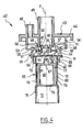
- valve 1 there is shown in Figures 1 and 2 a valve 1 according to a first exemplary embodiment of the invention.
- This valve 1 equips a fuel tank 2 which has only been partially represented for the sake of clarity of the drawing.
- a pump 3 takes fuel from the tank 2 and sends it to the injectors 4 of the vehicle engine.
- a regulator 5 is connected to the pump and to the injectors by lines 6 and 7 respective.
- This regulator 5 returns to the pump 3, via a return duct 8, the fuel which is not consumed by the injectors 4.
- the pump 3 advantageously forms with the regulator 5 and the conduits 6 and 8 an assembly introduced in one piece into the tank 2, which is shown schematically by dashed lines in Figures 1 and 2.
- the valve 1 comprises a body 9, substantially tubular, elongated along an axis X substantially vertical when the vehicle rests on a flat horizontal surface.
- This body is constituted in the example described by the assembly of a part lower 10 and upper 11.
- a transverse partition 12 perpendicular to the axis X delimits inside the body 9 a lower compartment 13 and an upper compartment 14.
- a conduit 16 connected to the degassing circuit passes through the upper compartment 14 and the partition 12 to open, through an orifice 17, in the lower compartment.
- the valve 1 comprises a member 18 movable in the body 9, making it possible to change the configuration of valve 1 depending on whether the tank is being filled with the engine stopped or the vehicle running.
- This member 18 comprises a skirt 19 which can slide along the axis X at the favor of an annular passage 21 passing through the partition 12.
- the skirt 19 is connected at its upper end to an annular plate 22 which extends perpendicular to the X axis in the upper compartment 14 and which can take support on the partition 12 to prevent the member 18 from falling into the lower compartment 13.
- the aforementioned plate 22 is dimensioned so that it can slide with a little play in the upper compartment 14.
- the skirt 19 extends radially inwards, at its lower end, to form a rim 24 whose end 25 is raised and supports a first element shutter 26 in the form of a disc.
- This disc 26 can move inside the member 18 between the end 27 of the duct 16 and the end 25 of the flange 24.
- the disc 26 is crossed in its center by an orifice 29.
- the skirt 19 is provided at about halfway with openings 30 whose role will be explained further.
- the valve 1 exploits the depression created by the Venturi effect at a nozzle 31 integrated in the return duct 8 to drive the moving member 18 and change the configuration of the valve.
- This nozzle 31 projects a jet of fuel 32 inside the conduit with a high speed as illustrated in Figure 2, which causes Venturi effect the appearance of a depression around the jet 32, which is transmitted to the compartment upper 14 of the valve 1 by a suction pipe 33.
- This depression tends to suck the plate 22 and lift the member 18, which then brings the disc 26 into a partially closed position of the orifice 17.
- the lower compartment 13 communicates with the interior of the tank at through openings 34 formed in the lower wall 35 of the valve 1.
- a second closure element 36 is movable in the lower compartment 13.
- This closure element 36 normally rests by its weight, when the tank is in a normal position of use, against ranges 38 and cleaning with the side wall of the valve 1 an annular space 40 allowing air and vapors fuel to win line 16.
- Openings are made between the surfaces 38.
- the closure element 36 is capable of holding the disc 26 by its weight. closed position of conduit 16 when in the event of accidental overturning of the vehicle, the tank is upside down, the boss 37 further closing the orifice 29 of the disc 26.
- the jet 32 creates a vacuum in the duct 33, which causes the suction of the plate 22 and its displacement upwards.
- the disc 26 is then pressed against the edge of the orifice 17 of the conduit 16, of so that the latter no longer communicates with the interior of the tank except through the orifice 29 of the disc 26.
- This opening 29 being of relatively small section, the tank is thus allowed to continue breathing while preventing possible projections due to waves of fuel in tank 2 to enter line 16.
- the conduit 16 is isolated from the tank 2 thanks to the second closure element 36 which closes with the boss 37 the hole 29 of the disc 26.
- valve 1 which has been described a spring not shown, intended to compensate for part of the weight of the shutter and to allow closing of the valve in the event of partial overturning of the vehicle.
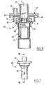
- valve 42 There is shown in Figures 3 to 8 a valve 42 according to a second exemplary embodiment of the invention.
- This valve 42 has a fixed upper part 43 provided with a flange 44 fixing on the wall of the tank, not shown, a central pipe 45 and a eccentric tube 46 used respectively for connecting the valve 42 respectively to the degassing circuit and to the suction duct described above.
- the central tube 45 has at its lower end 46 a rim interior 47 used for the attachment of a seat element 48, movable along the Y axis substantially vertical of the valve 42.
- This seat element 48 comprises an annular body 49 provided at its upper end of teeth 50 hooking onto flange 47.
- the body 49 is extended radially outwards in the vicinity of its lower end by a collar 51.
- An annular lip 52 projects under the flange 51 in the extension of the body 49.
- the fixed upper part 43 of the valve 42 includes a tubular skirt 53 coaxial with the central tube 45 and defining around the latter a groove annular 54, in the bottom of which opens the eccentric tube 46.
- the valve 42 comprises a member 55 movable vertically along the axis Y, at the interior of which the seat element 48 is located.
- This member 55 comprises in the upper part an annular plate 56 disposed in the groove 54 so as to slide with a slight clearance therein.
- the plate 56 defines inside the groove 54 an annular chamber 57 communicating through the tubing 46 with the suction duct, not shown.
- a wall 58 having a shoulder 59 extends below the tray 56.
- a guide ring 60 is attached to the lower end of the wall 58.
- the wall 58 has an annular lip 61 which projects downwards on the shoulder 59 to bear on the flange 51 of the seat element 48 when the valve is in the configuration of FIG. 4.
- the wall 58 further comprises a series of openings 64 located under the shoulder 59, making it possible to establish communication with the interior of the tank.
- a first closure element 65 is slidably mounted in the ring guide 60.
- This closure element 65 has an upper wall 66 extending perpendicular to the Y axis, crossed at its center by a central hole.
- the upper wall 66 further comprises on the side of the seat element 48, an annular bearing surface 68 slightly projecting and against which can come to apply in a substantially sealed manner the annular lip 52 when the valve 42 is in the configuration of Figure 5, as will be explained later.
- the upper wall 66 is also pierced with orifices 69 located radially at outside the bearing surface 68.
- the wall upper 66 rests by its periphery 70 on a shoulder 71 of the ring guide 60.
- the upper wall 66 is extended downwards by a side wall 72 cylindrical, provided with openings 73 in the lower part.
- An end element 75 is attached to the lower end of the wall lateral 72.
- This end element 75 is open only downwards and contains a air volume 76 sufficient for the first closure element to have a positive buoyancy in liquid fuel.
- a second closure element 77 is housed in the space 78 inside the side wall 72, between the upper wall 66 of the first closure element 65 and the upper wall 79 of the end element 75.
- This closure element 77 has a cylindrical body 80 closed at its upper end by a wall 81 and open only downwards, so as to contain sufficient air volume 82 to ensure flotation in the fuel liquid.
- the second closure element 77 has at its upper part a boss 83 shaped to close off the central orifice 67 of the upper wall 66 of the first closure element 65 when the valve is in the configuration of the figure 6, as will be explained later.
- valve 42 The operation of the valve 42 is as follows.
- the engine is stopped and the suction duct is not under vacuum, so that the annular chamber 57 is at the same pressure as the air present in the tank.
- the tank is empty so that the second closure element 77 weighs with all its weight on the first closure element 65 which itself rests entirely on the guide ring 60 of the member 55, which is supported by the lip 61 on the collar 51 of the seat element 48, as shown in FIG. 4.
- the teeth 50 of the seat element 48 hang on the inner rim 47 of the tubing 45 to retain the assembly.
- valve 42 offers a maximum passage section at the gas flow leaving the tank, driven by the incoming fuel.
- This gas stream mainly enters the valve 42 through the openings 64 and passes through the body of the seat element 48 to gain through the central tube 45 the degassing pipe.
- the first closure element 65 When the level of liquid fuel in the tank reaches the element end 75, the first closure element 65 is gradually raised under the effect of the fuel rising in the tank until it comes to a stop by the surface bearing 68 against the lip 52 of the seat element 48, as illustrated in the figure 5.
- valve is substantially closed and the filling of the tank is no longer possible.
- the member 55 drives in its displacement the first shutter element 65 which itself drives the seat element 48 until the flange 51 comes resting against the lower end of the tube 45, as shown in the figure 8.
- the upward displacement of the first closure element 65 has for consequence that the central orifice 67 is no longer blocked by the boss 83 of the second obturation element 77.
- the second element shutter 77 can lift and shut off momentarily, as the wave passes, the central opening 67, thus preventing splashes of liquid fuel from gaining tubing 45.
- magnetic means for example to ensure the upward movement of the member 18 of the embodiment of Figures 1 and 2 or of member 55 of the exemplary embodiment of FIGS. 3 to 8.
- These magnetic means can for example comprise an excited winding electrically so as to exert an electromagnetic force on member 18 or 55, the latter then being magnetizable.
Landscapes
- Engineering & Computer Science (AREA)
- Chemical & Material Sciences (AREA)
- Combustion & Propulsion (AREA)
- Mechanical Engineering (AREA)
- Life Sciences & Earth Sciences (AREA)
- Sustainable Development (AREA)
- Sustainable Energy (AREA)
- Transportation (AREA)
- General Engineering & Computer Science (AREA)
- Cooling, Air Intake And Gas Exhaust, And Fuel Tank Arrangements In Propulsion Units (AREA)
- Output Control And Ontrol Of Special Type Engine (AREA)
- Safety Valves (AREA)
Abstract
Description
- un organe mobile selon un axe sensiblement vertical, depuis une position inférieure lorsque le réservoir est en cours de remplissage et le moteur à l'arrêt à une position supérieure lorsque le moteur est en marche,
- un élément formant siège, mobile entre une position basse dans laquelle il s'accroche sur une partie fixe du clapet et supporte l'organe mobile et une position haute dans laquelle il vient en butée contre ladite partie fixe,
- un premier élément d'obturation présentant un orifice et déplaçable, lorsque l'organe mobile est en position basse, entre une première position dans laquelle il est écarté dudit élément formant siège et une deuxième position dans laquelle il vient en appui contre ledit élément formant siège et réduit la section de passage offerte à l'écoulement gazeux quittant le clapet, en ne permettant le passage qu'à travers ledit orifice, ce premier élément d'obturation présentant une flottabilité positive de manière à passer de sa première position vers sa deuxième position sous l'effet de la montée du carburant dans le réservoir,
- un deuxième élément d'obturation mobile par rapport au premier entre une première position dans laquelle il pèse sur le premier élément d'obturation et une deuxième position dans laquelle il obture ledit orifice du premier élément d'obturation, ce deuxième élément d'obturation présentant une flottabilité positive de manière à passer de sa première position vers sa deuxième position sous l'effet de la montée du carburant liquide dans le réservoir et fermer le clapet lorsque le réservoir est en fin de remplissage et le moteur à l'arrêt, l'organe mobile étant alors dans sa position basse,
- clapet dans lequel, après la mise en marche du moteur, l'organe mobile est en position haute et a entraíné l'élément formant siège dans sa position haute avec le premier élément d'obturation maintenu en appui contre l'élément formant siège par ledit organe mobile, l'orifice du premier élément d'obturation étant alors normalement ouvert en l'absence de vagues de carburant dans le réservoir, le deuxième élément d'obturation étant apte à obturer cet orifice sous l'effet d'une vague de carburant dans le réservoir.
- la figure 1 représente de façon schématique un clapet conforme à un premier exemple de réalisation de l'invention, lorsque le véhicule est au repos,
- la figure 2 représente le clapet de la figure 1 lorsque le moteur est en marche,
- la figure 3 est une vue en élévation d'un clapet conforme à un deuxième exemple de réalisation de l'invention,
- la figure 4 est une coupe longitudinale selon le trait de coupe IV-IV de la figure 3, le clapet étant représenté au début du remplissage,
- la figure 5 est une coupe analogue à la figure 4, représentant le clapet peu de temps avant la fin du remplissage,
- la figure 6 est une coupe analogue à la figure 4, représentant le clapet à la fin du remplissage,
- la figure 7 est une vue en élévation représentant le clapet lors du roulage, et
- la figure 8 est une coupe analogue à la figure 4, représentant le clapet pendant le roulage.
Claims (14)
clapet dans lequel, après la mise en marche du moteur, l'organe mobile est en position haute et a entraíné l'élément formant siège dans une position haute avec le premier élément d'obturation (65) maintenu en appui contre l'élément formant siège (48) par ledit organe mobile (55), l'orifice (67) du premier élément d'obturation (65) étant alors normalement ouvert en l'absence de vagues de carburant dans le réservoir, le deuxième élément d'obturation (77) étant apte à obturer cet orifice sous l'effet d'une vague de carburant dans le réservoir.
Applications Claiming Priority (2)
| Application Number | Priority Date | Filing Date | Title |
|---|---|---|---|
| FR9916354A FR2802862B1 (fr) | 1999-12-23 | 1999-12-23 | Clapet pour reservoir de carburant de vehicule automobile |
| FR9916354 | 1999-12-23 |
Publications (2)
| Publication Number | Publication Date |
|---|---|
| EP1112886A1 true EP1112886A1 (fr) | 2001-07-04 |
| EP1112886B1 EP1112886B1 (fr) | 2004-04-14 |
Family
ID=9553727
Family Applications (1)
| Application Number | Title | Priority Date | Filing Date |
|---|---|---|---|
| EP00403662A Expired - Lifetime EP1112886B1 (fr) | 1999-12-23 | 2000-12-22 | Clapet pour réservoir à carburant de véhicule automobile |
Country Status (5)
| Country | Link |
|---|---|
| US (1) | US6412511B1 (fr) |
| EP (1) | EP1112886B1 (fr) |
| AT (1) | ATE264205T1 (fr) |
| DE (1) | DE60009849T2 (fr) |
| FR (1) | FR2802862B1 (fr) |
Cited By (1)
| Publication number | Priority date | Publication date | Assignee | Title |
|---|---|---|---|---|
| FR2896568A1 (fr) * | 2006-01-26 | 2007-07-27 | Inergy Automotive Systems Res | Dispositif pour circuit de mise a l'air d'un reservoir a liquide et clapet integrant ledit dispositif |
Families Citing this family (8)
| Publication number | Priority date | Publication date | Assignee | Title |
|---|---|---|---|---|
| FR2802861B1 (fr) * | 1999-12-23 | 2002-03-15 | Plastic Omnium Cie | Clapet pour reservoir de carburant et reservoir ainsi equipe |
| JP2002061765A (ja) * | 2000-06-08 | 2002-02-28 | Toyoda Gosei Co Ltd | 燃料遮断弁 |
| US20030205272A1 (en) * | 2002-05-02 | 2003-11-06 | Eaton Corporation | Method of venting fuel vapor from a tank and system therefor |
| JP4135664B2 (ja) * | 2003-05-30 | 2008-08-20 | 豊田合成株式会社 | 燃料遮断弁 |
| DE102010055313A1 (de) | 2010-12-21 | 2012-06-21 | Audi Ag | Verfahren zum Betreiben eines Kraftstoffsystems sowie Kraftstoffsystem |
| JP5836984B2 (ja) * | 2013-01-30 | 2015-12-24 | 八千代工業株式会社 | 燃料タンク用バルブ |
| DE102013013213B4 (de) * | 2013-08-09 | 2016-07-07 | Kautex Textron Gmbh & Co. Kg | Betriebsflüssigkeitsbehälter mit integriertem Ent- und/oder Belüftungsventil |
| JP6610580B2 (ja) * | 2017-02-28 | 2019-11-27 | トヨタ自動車株式会社 | 燃料タンクシステム |
Citations (3)
| Publication number | Priority date | Publication date | Assignee | Title |
|---|---|---|---|---|
| US5259412A (en) * | 1992-08-14 | 1993-11-09 | Tillotson, Ltd. | Fuel tank vapor recovery control |
| US5261439A (en) * | 1991-02-22 | 1993-11-16 | Stant Manufacturing Inc. | Vacuum-actuated vent assembly |
| DE4400450A1 (de) * | 1993-01-13 | 1994-07-14 | Fuji Heavy Ind Ltd | Drucksteuervorrichtung für einen Kraftstofftank |
Family Cites Families (7)
| Publication number | Priority date | Publication date | Assignee | Title |
|---|---|---|---|---|
| US4991615A (en) * | 1990-03-02 | 1991-02-12 | Stant Inc. | Tank pressure control apparatus |
| US5590697A (en) * | 1994-08-24 | 1997-01-07 | G. T. Products, Inc. | Onboard vapor recovery system with two-stage shutoff valve |
| WO1998015761A1 (fr) * | 1996-10-09 | 1998-04-16 | G.T. Products, Inc. | Appareil et procede d'etalonnage de soupape a flotteur |
| US5960816A (en) * | 1997-03-26 | 1999-10-05 | G.T. Products, Inc. | Adjustable length vent valve system for fuel tanks |
| US6145532A (en) * | 1997-12-01 | 2000-11-14 | Walbro Corporation | Fuel tank fill level control and vapor venting valve |
| US5996607A (en) * | 1998-04-15 | 1999-12-07 | Eaton Corporation | Installing a fill limiting vent valve in a fuel tank |
| US6085771A (en) * | 1998-10-29 | 2000-07-11 | Eaton Corporation | Two-stage fuel tank vapor recovery vent valve and method of making same |
-
1999
- 1999-12-23 FR FR9916354A patent/FR2802862B1/fr not_active Expired - Fee Related
-
2000
- 2000-12-22 AT AT00403662T patent/ATE264205T1/de not_active IP Right Cessation
- 2000-12-22 DE DE60009849T patent/DE60009849T2/de not_active Expired - Lifetime
- 2000-12-22 EP EP00403662A patent/EP1112886B1/fr not_active Expired - Lifetime
- 2000-12-26 US US09/745,556 patent/US6412511B1/en not_active Expired - Lifetime
Patent Citations (3)
| Publication number | Priority date | Publication date | Assignee | Title |
|---|---|---|---|---|
| US5261439A (en) * | 1991-02-22 | 1993-11-16 | Stant Manufacturing Inc. | Vacuum-actuated vent assembly |
| US5259412A (en) * | 1992-08-14 | 1993-11-09 | Tillotson, Ltd. | Fuel tank vapor recovery control |
| DE4400450A1 (de) * | 1993-01-13 | 1994-07-14 | Fuji Heavy Ind Ltd | Drucksteuervorrichtung für einen Kraftstofftank |
Cited By (3)
| Publication number | Priority date | Publication date | Assignee | Title |
|---|---|---|---|---|
| FR2896568A1 (fr) * | 2006-01-26 | 2007-07-27 | Inergy Automotive Systems Res | Dispositif pour circuit de mise a l'air d'un reservoir a liquide et clapet integrant ledit dispositif |
| WO2007085585A1 (fr) * | 2006-01-26 | 2007-08-02 | Inergy Automotive Systems Research (Société Anonyme) | Soupape de mise à l'air libre |
| US8118051B2 (en) | 2006-01-26 | 2012-02-21 | Inergy Automotive Systems Research (Societe Anonyme) | Valve for the venting circuit of a liquid tank |
Also Published As
| Publication number | Publication date |
|---|---|
| EP1112886B1 (fr) | 2004-04-14 |
| ATE264205T1 (de) | 2004-04-15 |
| US6412511B1 (en) | 2002-07-02 |
| DE60009849T2 (de) | 2005-04-21 |
| FR2802862A1 (fr) | 2001-06-29 |
| FR2802862B1 (fr) | 2002-03-22 |
| DE60009849D1 (de) | 2004-05-19 |
Similar Documents
| Publication | Publication Date | Title |
|---|---|---|
| EP0254631B1 (fr) | Dispositif d'aération d'un réservoir de carburant | |
| EP0928252B1 (fr) | Dispositif de puisage de carburant pour reservoir de vehicules automobiles | |
| FR2770464A1 (fr) | Appareil de controle de vapeurs d'un reservoir de carburant | |
| BE1012390A3 (fr) | Systeme de mise a l'air de reservoir a liquide. | |
| FR2739612A1 (fr) | Appareil de commande de vapeurs de reservoir de carcurant d'un vehicule | |
| EP1112886B1 (fr) | Clapet pour réservoir à carburant de véhicule automobile | |
| WO1999061275A1 (fr) | Dispositif de mise a l'air libre d'un reservoir de carburant de vehicule automobile | |
| EP1110789B1 (fr) | Clapet pour réservoir de carburant et réservoir ainsi équipé | |
| FR2674551A1 (fr) | Chasse hydropneumatique pour reservoir de cabinet. | |
| FR2864169A1 (fr) | Filtre a carburant a evacuation d'eau facilitee | |
| EP0300910A1 (fr) | Dispositif de filtrage et de dégazage d'un carburant d'alimentation pour moteur à combustion interne | |
| FR2954805A1 (fr) | Clapet pour circuit de mise a l'air d'un reservoir a liquide | |
| FR2736592A1 (fr) | Appareil de remplissage de carburant et de retenue de vapeurs pour reservoir de carburant d'un vehicule | |
| FR2755911A1 (fr) | Reservoir de carburant pour vehicules automobiles | |
| EP0774372B1 (fr) | Dispositif de mise à l'air libre perfectionné pour réservoir de carburant de véhicule automobile et réservoir comportant ce dispositif | |
| EP0976597B1 (fr) | Clapet pour réservoir à carburant de véhicle automobile | |
| FR2580190A1 (fr) | Filtre a carburant et circuit d'alimentation en carburant equipe de ce filtre | |
| FR2669864A1 (fr) | Clapet de ventilation pour un reservoir de carburant d'un vehicule. | |
| EP0344063B1 (fr) | Dispositif de dégazage à haute efficacité d'un carburant d'alimentation de moteur à combustion interne | |
| FR2996279A1 (fr) | Clapet de ventilation pour reservoir a liquide integrant une securite anti-surpression. | |
| FR2798276A1 (fr) | Aspirateur a cuve | |
| FR2686840A1 (fr) | Dispositif d'aeration pour reservoir de carburant. | |
| EP0516528B1 (fr) | Clapet de sécurité pour circuit de ventilation d'un réservoir de carburant de véhicule automobile | |
| EP0749860A1 (fr) | Dispositif de puisage perfectionné pour carburant dans un réservoir de véhicule automobile | |
| FR2774636A1 (fr) | Dispositif de mise a l'air libre d'un reservoir de carburant de vehicule automobile |
Legal Events
| Date | Code | Title | Description |
|---|---|---|---|
| PUAI | Public reference made under article 153(3) epc to a published international application that has entered the european phase |
Free format text: ORIGINAL CODE: 0009012 |
|
| AK | Designated contracting states |
Kind code of ref document: A1 Designated state(s): AT BE CH CY DE DK ES FI FR GB GR IE IT LI LU MC NL PT SE TR |
|
| AX | Request for extension of the european patent |
Free format text: AL;LT;LV;MK;RO;SI |
|
| 17P | Request for examination filed |
Effective date: 20011207 |
|
| AKX | Designation fees paid |
Free format text: AT BE CH CY DE DK ES FI FR GB GR IE IT LI LU MC NL PT SE TR |
|
| 17Q | First examination report despatched |
Effective date: 20021205 |
|
| GRAH | Despatch of communication of intention to grant a patent |
Free format text: ORIGINAL CODE: EPIDOS IGRA |
|
| GRAS | Grant fee paid |
Free format text: ORIGINAL CODE: EPIDOSNIGR3 |
|
| GRAA | (expected) grant |
Free format text: ORIGINAL CODE: 0009210 |
|
| AK | Designated contracting states |
Kind code of ref document: B1 Designated state(s): AT BE CH CY DE DK ES FI FR GB GR IE IT LI LU MC NL PT SE TR |
|
| PG25 | Lapsed in a contracting state [announced via postgrant information from national office to epo] |
Ref country code: IT Free format text: LAPSE BECAUSE OF FAILURE TO SUBMIT A TRANSLATION OF THE DESCRIPTION OR TO PAY THE FEE WITHIN THE PRESCRIBED TIME-LIMIT;WARNING: LAPSES OF ITALIAN PATENTS WITH EFFECTIVE DATE BEFORE 2007 MAY HAVE OCCURRED AT ANY TIME BEFORE 2007. THE CORRECT EFFECTIVE DATE MAY BE DIFFERENT FROM THE ONE RECORDED. Effective date: 20040414 Ref country code: IE Free format text: LAPSE BECAUSE OF FAILURE TO SUBMIT A TRANSLATION OF THE DESCRIPTION OR TO PAY THE FEE WITHIN THE PRESCRIBED TIME-LIMIT Effective date: 20040414 Ref country code: NL Free format text: LAPSE BECAUSE OF FAILURE TO SUBMIT A TRANSLATION OF THE DESCRIPTION OR TO PAY THE FEE WITHIN THE PRESCRIBED TIME-LIMIT Effective date: 20040414 Ref country code: CY Free format text: LAPSE BECAUSE OF FAILURE TO SUBMIT A TRANSLATION OF THE DESCRIPTION OR TO PAY THE FEE WITHIN THE PRESCRIBED TIME-LIMIT Effective date: 20040414 Ref country code: AT Free format text: LAPSE BECAUSE OF FAILURE TO SUBMIT A TRANSLATION OF THE DESCRIPTION OR TO PAY THE FEE WITHIN THE PRESCRIBED TIME-LIMIT Effective date: 20040414 Ref country code: GB Free format text: LAPSE BECAUSE OF FAILURE TO SUBMIT A TRANSLATION OF THE DESCRIPTION OR TO PAY THE FEE WITHIN THE PRESCRIBED TIME-LIMIT Effective date: 20040414 Ref country code: TR Free format text: LAPSE BECAUSE OF FAILURE TO SUBMIT A TRANSLATION OF THE DESCRIPTION OR TO PAY THE FEE WITHIN THE PRESCRIBED TIME-LIMIT Effective date: 20040414 Ref country code: FI Free format text: LAPSE BECAUSE OF FAILURE TO SUBMIT A TRANSLATION OF THE DESCRIPTION OR TO PAY THE FEE WITHIN THE PRESCRIBED TIME-LIMIT Effective date: 20040414 |
|
| REG | Reference to a national code |
Ref country code: GB Ref legal event code: FG4D Free format text: NOT ENGLISH |
|
| REG | Reference to a national code |
Ref country code: CH Ref legal event code: EP |
|
| REF | Corresponds to: |
Ref document number: 60009849 Country of ref document: DE Date of ref document: 20040519 Kind code of ref document: P |
|
| REG | Reference to a national code |
Ref country code: IE Ref legal event code: FG4D Free format text: FRENCH |
|
| PG25 | Lapsed in a contracting state [announced via postgrant information from national office to epo] |
Ref country code: SE Free format text: LAPSE BECAUSE OF FAILURE TO SUBMIT A TRANSLATION OF THE DESCRIPTION OR TO PAY THE FEE WITHIN THE PRESCRIBED TIME-LIMIT Effective date: 20040714 Ref country code: DK Free format text: LAPSE BECAUSE OF FAILURE TO SUBMIT A TRANSLATION OF THE DESCRIPTION OR TO PAY THE FEE WITHIN THE PRESCRIBED TIME-LIMIT Effective date: 20040714 Ref country code: GR Free format text: LAPSE BECAUSE OF FAILURE TO SUBMIT A TRANSLATION OF THE DESCRIPTION OR TO PAY THE FEE WITHIN THE PRESCRIBED TIME-LIMIT Effective date: 20040714 |
|
| PG25 | Lapsed in a contracting state [announced via postgrant information from national office to epo] |
Ref country code: ES Free format text: LAPSE BECAUSE OF FAILURE TO SUBMIT A TRANSLATION OF THE DESCRIPTION OR TO PAY THE FEE WITHIN THE PRESCRIBED TIME-LIMIT Effective date: 20040725 |
|
| NLV1 | Nl: lapsed or annulled due to failure to fulfill the requirements of art. 29p and 29m of the patents act | ||
| GBV | Gb: ep patent (uk) treated as always having been void in accordance with gb section 77(7)/1977 [no translation filed] |
Effective date: 20040414 |
|
| REG | Reference to a national code |
Ref country code: IE Ref legal event code: FD4D |
|
| RAP2 | Party data changed (patent owner data changed or rights of a patent transferred) |
Owner name: INERGY AUTOMOTIVE SYSTEMS RESEARCH (SOCIETE ANONYM |
|
| PG25 | Lapsed in a contracting state [announced via postgrant information from national office to epo] |
Ref country code: LU Free format text: LAPSE BECAUSE OF NON-PAYMENT OF DUE FEES Effective date: 20041222 |
|
| PG25 | Lapsed in a contracting state [announced via postgrant information from national office to epo] |
Ref country code: LI Free format text: LAPSE BECAUSE OF NON-PAYMENT OF DUE FEES Effective date: 20041231 Ref country code: BE Free format text: LAPSE BECAUSE OF NON-PAYMENT OF DUE FEES Effective date: 20041231 Ref country code: CH Free format text: LAPSE BECAUSE OF NON-PAYMENT OF DUE FEES Effective date: 20041231 Ref country code: MC Free format text: LAPSE BECAUSE OF NON-PAYMENT OF DUE FEES Effective date: 20041231 |
|
| PLBE | No opposition filed within time limit |
Free format text: ORIGINAL CODE: 0009261 |
|
| STAA | Information on the status of an ep patent application or granted ep patent |
Free format text: STATUS: NO OPPOSITION FILED WITHIN TIME LIMIT |
|
| REG | Reference to a national code |
Ref country code: FR Ref legal event code: TP |
|
| 26N | No opposition filed |
Effective date: 20050117 |
|
| BERE | Be: lapsed |
Owner name: CIE *PLASTIC OMNIUM Effective date: 20041231 |
|
| REG | Reference to a national code |
Ref country code: CH Ref legal event code: PL |
|
| BERE | Be: lapsed |
Owner name: CIE *PLASTIC OMNIUM Effective date: 20041231 |
|
| PG25 | Lapsed in a contracting state [announced via postgrant information from national office to epo] |
Ref country code: PT Free format text: LAPSE BECAUSE OF NON-PAYMENT OF DUE FEES Effective date: 20040914 |
|
| PGFP | Annual fee paid to national office [announced via postgrant information from national office to epo] |
Ref country code: FR Payment date: 20071210 Year of fee payment: 8 |
|
| REG | Reference to a national code |
Ref country code: FR Ref legal event code: ST Effective date: 20090831 |
|
| PG25 | Lapsed in a contracting state [announced via postgrant information from national office to epo] |
Ref country code: FR Free format text: LAPSE BECAUSE OF NON-PAYMENT OF DUE FEES Effective date: 20081231 |
|
| PGFP | Annual fee paid to national office [announced via postgrant information from national office to epo] |
Ref country code: DE Payment date: 20171228 Year of fee payment: 18 |
|
| REG | Reference to a national code |
Ref country code: DE Ref legal event code: R119 Ref document number: 60009849 Country of ref document: DE |
|
| PG25 | Lapsed in a contracting state [announced via postgrant information from national office to epo] |
Ref country code: DE Free format text: LAPSE BECAUSE OF NON-PAYMENT OF DUE FEES Effective date: 20190702 |