EP1112851A1 - Misregistration correction for bidirectional printing in consideration of inclination of nozzle array - Google Patents
Misregistration correction for bidirectional printing in consideration of inclination of nozzle array Download PDFInfo
- Publication number
- EP1112851A1 EP1112851A1 EP00944294A EP00944294A EP1112851A1 EP 1112851 A1 EP1112851 A1 EP 1112851A1 EP 00944294 A EP00944294 A EP 00944294A EP 00944294 A EP00944294 A EP 00944294A EP 1112851 A1 EP1112851 A1 EP 1112851A1
- Authority
- EP
- European Patent Office
- Prior art keywords
- misalignment
- correction value
- nozzle array
- printing
- scanning direction
- Prior art date
- Legal status (The legal status is an assumption and is not a legal conclusion. Google has not performed a legal analysis and makes no representation as to the accuracy of the status listed.)
- Granted
Links
Images





Classifications
-
- B—PERFORMING OPERATIONS; TRANSPORTING
- B41—PRINTING; LINING MACHINES; TYPEWRITERS; STAMPS
- B41J—TYPEWRITERS; SELECTIVE PRINTING MECHANISMS, i.e. MECHANISMS PRINTING OTHERWISE THAN FROM A FORME; CORRECTION OF TYPOGRAPHICAL ERRORS
- B41J19/00—Character- or line-spacing mechanisms
- B41J19/14—Character- or line-spacing mechanisms with means for effecting line or character spacing in either direction
- B41J19/142—Character- or line-spacing mechanisms with means for effecting line or character spacing in either direction with a reciprocating print head printing in both directions across the paper width
- B41J19/145—Dot misalignment correction
-
- B—PERFORMING OPERATIONS; TRANSPORTING
- B41—PRINTING; LINING MACHINES; TYPEWRITERS; STAMPS
- B41J—TYPEWRITERS; SELECTIVE PRINTING MECHANISMS, i.e. MECHANISMS PRINTING OTHERWISE THAN FROM A FORME; CORRECTION OF TYPOGRAPHICAL ERRORS
- B41J2/00—Typewriters or selective printing mechanisms characterised by the printing or marking process for which they are designed
- B41J2/005—Typewriters or selective printing mechanisms characterised by the printing or marking process for which they are designed characterised by bringing liquid or particles selectively into contact with a printing material
- B41J2/01—Ink jet
- B41J2/135—Nozzles
- B41J2/145—Arrangement thereof
- B41J2/15—Arrangement thereof for serial printing
-
- B—PERFORMING OPERATIONS; TRANSPORTING
- B41—PRINTING; LINING MACHINES; TYPEWRITERS; STAMPS
- B41J—TYPEWRITERS; SELECTIVE PRINTING MECHANISMS, i.e. MECHANISMS PRINTING OTHERWISE THAN FROM A FORME; CORRECTION OF TYPOGRAPHICAL ERRORS
- B41J2202/00—Embodiments of or processes related to ink-jet or thermal heads
- B41J2202/01—Embodiments of or processes related to ink-jet heads
- B41J2202/20—Modules
Definitions
- the present invention relates to a technique that carries out bidirectional, reciprocating main scan to print an image on a printing medium. More specifically the present invention pertains to a technique that adjusts misalignment of dot recording positions in a main scanning direction between a forward pass and a backward pass of the main scan.
- color printers having a print head that ejects a plurality of different color inks have been widely used as an output device of computers. Some of such color printers have the function of "bidirectional printing" for the enhancing printing speed.
- JPA 5-69625 filed by the applicant of the present invention.
- This prior art technique registers in advance a potential amount of positional misalignment (deviation in printing) in the main scanning direction and corrects the dot recording positions on the forward pass and on the backward pass, based on the registered amount of positional misalignment.
- the print head of the printer generally has a nozzle array that includes a large number of nozzles arranged in a sub-scanning direction.
- mechanical vibrations may occur on the print head to slightly shift the orientation of the nozzle array from the sub-scanning direction.
- the nozzle array may be slightly inclined to different orientations on the forward pass and on the backward pass, for example, due to the backlash of the driving mechanism in the main scanning direction. In such cases, it is difficult to accurately determine the amount of potential positional misalignment, since the nozzle array does not move back and forth keeping the specified posture perpendicular to the main scanning direction as a whole.
- the object of the present invention is to solve the problem of the prior art technique discussed above and accordingly to provide a technique that relieves positional misalignment in the main scanning direction on a forward pass and a backward pass of main scan with regard to a nozzle array in a printing apparatus of bidirectional printing.
- the present invention is directed to a printing apparatus that comprises a print head having a nozzle array, which is arranged in a sub-scanning direction and ejects ink droplets to record dots on a printing medium, and carries out bidirectional, reciprocating main scan to complete print on the printing medium.
- a positional misalignment test pattern is printed on the printing medium with a representative nozzle sub-array, which is part of the nozzle array and is within a predetermined range around a center ofthe nozzle array.
- the representative nozzle sub-array that is within a predetermined range around a center ofthe nozzle array represents a group of plural nozzles that includes a specific nozzle closest to the center position along the length of the nozzle array and does not include end nozzles on either end of the nozzle array.
- the arrangement of the present invention determines the correction value on the basis of the nozzles in the neighborhood of the center of the nozzle array. Accordingly , it reduces the total misalignment of dot recording positions, due to the variation in the angle of the nozzle array.
- the technique of the invention determines the correction value according to the correction information which represents the favorable correction state selected based on the positional misalignment test pattern printed with the representative nozzle sub-array. The correction value is determined not on the basis of deductive inference but on the basis of the positional misalignment test pattern actually printed on a printing medium. The correction value can thus be determined adequately to relieve the actual printing misalignment.
- the nozzle array preferably comprises: a color nozzle array including a plurality of color nozzles to eject color ink that are arranged in a predetermined sequence in the sub-scanning direction; and a black nozzle array including a plurality of black nozzles to eject black ink that are arranged in a predetermined sequence in the sub-scanning direction.
- a memory included in the printing apparatus stores a first correction value and a second correction value therein.
- the first correction value is set for correcting the positional misalignment of recording positions in the main scanning direction on the forward pass and the backward pass of the main scan with regard to a representative color nozzle sub-array, which is part of the color nozzle array and is within a predetermined range around a center of the color nozzle array.
- the second correction value is set for correcting the positional misalignment of recording positions in the main scanning direction on the forward pass and the backward pass of the main scan with regard to a representative black nozzle sub-array, which is part of the black nozzle array and is within a predetermined range around a center of the black nozzle array.
- the color nozzle array and the black nozzle array may have any positional relationship.
- This arrangement corrects the misalignment of recording positions in the course of bidirectional printing with the first correction value, which reflects the characteristics of the color nozzle array, and with the second correction value, which reflects the characteristics of the black nozzle array. Namely the arrangement of using both the first correction value and the second correction value can reflect the characteristics of the color nozzle array and the black nozzle array on the correction of the misalignment of recording positions in the course of bidirectional printing.
- the positional misalignment correction unit may correct the misalignment of recording positions in the main scanning direction in the course of bidirectional printing with regard to the nozzle array with a mean value of the first correction value and the second correction value. This arrangement readily corrects the misalignment of recording positions in the course of bidirectional printing by taking into account both the color nozzle array and the black nozzle array.
- the positional misalignment correction unit corrects the misalignment of recording positions with the first correction value in a print mode that the nozzles of the color nozzle array are used.
- this arrangement carries out the correction with the first correction value that reflects the characteristics of the color nozzle array. This accordingly ensures the correction of recording positions suitable for color printing.
- the positional misalignment correction unit corrects the misalignment of recording positions with the second correction value in a print mode that the nozzles of the color nozzle array are not used.
- this arrangement carries out the correction with the second correction value that reflects the characteristics of the black nozzle array. This accordingly ensures the correction of recording positions suitable for monochromatic printing.
- the positional misalignment correction unit may correct the misalignment of recording positions with the first correction value with regard to the color nozzle array, and corrects the misalignment of recording positions with the second correction value with regard to the black nozzle array. This arrangement ensures the optimum corrections for both the color nozzle array and the black nozzle array in the process of one printing operation.
- the color nozzle array includes yellow nozzles for ejecting yellow ink, cyan nozzles for ejecting cyan ink, and magenta nozzles for ejecting magenta ink, and that the representative color nozzle sub-array consists of either of cyan nozzles and magenta nozzles.
- the nozzles in the neighborhood of both the ends of the nozzle array have a greater degree of misalignment of dot recording positions in the main scanning direction than the nozzles in the neighborhood of the center of the nozzle array.
- the misalignment of recording positions in yellow is least conspicuous.
- the misalignment of recording positions in magenta and cyan is more conspicuous than that in yellow.
- the cyan nozzles or the magenta nozzles are arranged in the neighborhood of the center of the nozzle array and the correction value is determined with either the cyan nozzles or the magenta nozzles as the representative color nozzle sub-array. This arrangement makes the total misalignment of recording positions of dots sufficiently inconspicuous.
- the present invention is realized by a diversity of applications as given below:
- Fig. 1 schematically illustrates the structure of a printing system including an ink jet printer 20 in a first embodiment of the present invention.
- the printer 20 includes a sub-scan mechanism that drives a sheet feed motor 22 to feed a sheet of printing paper P in a sub-scanning direction, a main scan mechanism that drives a carriage motor 24 to move a carriage 30 back and forth along an axis of a platen 26 (in a main scanning direction), a head driving mechanism that drives a print head unit 60 (also referred to as "print head assembly”) mounted on the carriage 30 to control ejection of ink and creation of dots, and a control circuit 40 that controls transmission of signals to and from the sheet feed motor 22, the carriage motor 24, the print head unit 60, and a control panel 32.
- the control circuit 40 is connected to a computer 88 via a connector 56.
- the sub-scan mechanism for feeding the printing paper P has a gear train (not shown) that transmits the rotations of the sheet feed motor 22 to the platen 26 and a sheet feed roller (not shown).
- the main scan mechanism for reciprocating the carriage 30 includes a sliding shaft 34 that is arranged in parallel with the axis of the platen 26 to support the carriage 30 in a slidable manner, a pulley 38 that is combined with the carriage motor 24 to support an endless drive belt 36 spanned therebetween, and a position sensor 39 that detects the starting position of the carriage 30. Another arrangement may alternatively be applied for the main scan and the sub-scan.
- the printer carries out the bidirectional, reciprocating main scan to change the relative position of the print head to the printing medium while ejecting ink from the nozzles and also performs the sub-scan between adjoining passes of the main scan to change the relative position of the print head to the printing medium in a direction different from the direction of the main scan, thereby effecting print on the printing medium.
- Fig. 2 is a block diagram showing the structure of the control circuit 40 included in the printer 20.
- the control circuit 40 is constructed as an arithmetic and logic operation circuit including a CPU 41, a programmable ROM (PROM) 43, a RAM 44, and a character generator (CG) 45 that stores dot matrixes of characters.
- the control circuit 40 further includes a dedicated I/F circuit 50 that dedicatedly works as an interface with external elements like a motor, a head driver 52 that connects with the dedicated I/F circuit 50 and drives the print head unit 60 to eject ink, and a motor driver 54 that drives the sheet feed motor 22 and the carriage motor 24.
- the dedicated I/F circuit 50 includes a parallel interface circuit and receives a print signal PS supplied from the computer 88 via the connector 56.
- the print head unit 60 includes a housing in which an ink cartridge for containing ink therein is housed, and a print head 28 that is a mechanism of ejecting ink droplets.
- the whole configuration including the print head 28 and the housing for the ink cartridge is called the "print head unit 60", since the print head unit 60 is attached to and detached from the printer 20 as an unitary part. Namely replacement of the print head 28 requires replacement of the print head unit 60.
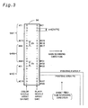
- Fig. 3 shows an arrangement of nozzles formed on a bottom face of an actuator chip 94, which is disposed on a lower portion of the print head 28.
- a color nozzle array and a black nozzle array are formed on the bottom face of the actuator chip 94 and are respectively aligned in lines in the sub-scanning direction.
- the term "actuator” here means an ink ejection mechanism including nozzles and driving elements for ink ejection (for example, piezoelectric elements or heaters).
- a nozzle section in one actuator is generally molded as an integral ceramic part. Formation of two columns of nozzles in one actuator enables the highly accurate layout of nozzles and thereby improves the image quality.
- the "column of nozzles" is also be referred to as the "nozzle array”.
- the black nozzle array includes 48 nozzles #K1 through #K48. These nozzles #K1 through #K48 are arranged at a fixed nozzle pitch k in the sub-scanning direction.
- the nozzle pitch k is equal to 6 dots in this embodiment.
- the nozzle pitch k may be set to any other value that is obtained by multiplying the dot pitch on the printing medium P by an arbitrary integer of 2 or more.
- the color nozzle array includes a yellow nozzle group 94Y, a magenta nozzle group 94M, and a cyan nozzle group 94C.
- the nozzle group of a colored ink is also referred to as the "chromatic nozzle group”.
- the yellow nozzle group 94Y includes 15 nozzles #Y1 through #Y15. The pitch of these 15 nozzles is identical with the nozzle pitch k of the black nozzle array. This nozzle pitch k is also applied for the magenta nozzle group 94M and the cyan nozzle group 94C.
- a symbol "x" drawn between the lower end nozzle #Y15 of the yellow nozzle group 94Y and the upper end nozzle #M1 of the magenta nozzle group 94M represents no presence of a nozzle at the position.
- the interval between the lower end nozzle #Y15 of the yellow nozzle group 94Y and the upper end nozzle #M1 of the magenta nozzle group 94M is accordingly double the nozzle pitch k.
- This double nozzle pitch is also applied for the interval between the lower end nozzle #M15 of the magenta nozzle group 94M and the upper end nozzle #C1 of the cyan nozzle group 94C.
- the intervals between the respective nozzle groups of yellow, magenta, and cyan are set to be double the nozzle pitch k.
- Each of the nozzles in the color nozzle groups 94Y, 94M, and 94C is located at an identical position in the sub-scanning direction with the corresponding nozzle of the black nozzle array 94K. There are, however, no colored ink nozzles at the positions corresponding to the 16 th , 32 nd , and 48 th nozzles #K16, #K32, and #K48 among the 48 nozzles #K1 through #K48 of the black nozzle array 94K.
- ink droplets are ejected from the respective nozzles while the print head 28 is moving in the main scanning direction together with the carriage 30 (see Fig. 1).
- all the nozzles are not always used, but only part of the nozzles may be used.
- the bidirectional printing creates dots in both the forward pass and the backward pass of the main scan to print one image on the printing medium P. Accordingly, when ink is ejected aiming at the same recording position on the forward pass and on the backward pass of printing, dots should actually be recorded at the same position on the printing medium P. This is because an image can be properly reproduced by combination of dots formed in the forward pass and dots formed in the backward pass only when ink aiming at the same recording position actually forms dots at the same position on the printing medium P.
- the recording positions in the main scanning direction may be misaligned on the forward pass and the backward pass of the main scan, due to a backlash of the driving mechanism in the main scanning direction or a warp of the platen that supports the printing medium thereon.
- This method of correcting the misalignment of recording positions intentionally shifts the ejection timings of ink droplets on the forward pass and on the backward pass from the "theoretical timings to record dots at the same recording position.”
- This method accordingly absorbs the misalignment of recording positions and implements the correction, in order to ensure actual recording of dots at the same recording position.
- Fig. 4 shows the principle of determining a correction value for adjusting the misalignment based on a test pattern.
- the test pattern is printed by causing the black nozzles #K1 through #K48 to create dots on the printing medium P while the print head 28is moving back and forth in the main scanning direction without any feed in the sub-scanning direction.
- ink droplets are ejected to form ruled lines on the printing medium P at fixed intervals in the sub-scanning direction.
- the solid lines with numerals 1 through 8 allocated thereto represent the ruled lines printed on the forward pass.
- the ruled line is printed at different timings, that is, at several different printing positions, so that user can select the "timing of recording a ruled line completely overlapping the ruled line recorded on the forward pass".
- the ruled lines printed on the backward pass are shown by the broken lines.
- the ruled line that is formed by ink droplets ejected on the backward pass at the "theoretical timing to record an identical ruled line" is the fourth left ruled line.
- the three left ruled lines from the third to the leftmost ruled line are printed at delayed ejection timings of ink droplets, so that those are formed on the backward pass slightly shifted leftward from the ruled lines formed on the forward pass.
- the four right ruled lines from the fifth to the rightmost ruled line are printed at advanced ejection timings of ink droplets, on the other hand, so that the ruled lines are formed on the backward pass slightly shifted rightward from those formed on the forward pass. This results in the test pattern printed on the printing medium P as shown in Fig. 4.
- the ruled lines Nos. 1 through 8 printed on the backward pass are shifted rightward sequentially from the left end by one dot pitch relative to the corresponding ruled lines printed on the forward pass.
- the correction value is accordingly set as an integral multiple of the dot pitch.
- This example shifts the ruled lines printed on the backward pass by one dot pitch.
- the correction value can be set as an integral multiple of the finer unit.
- the ruled lines formed on the backward pass are shown by the broken lines. This is only for the purpose of distinguishing the ruled lines formed on the backward pass from those formed on the forward pass and does not necessarily mean that the ruled lines are actually printed in broken line on the backward pass.
- This procedure prints the ruled lines on the backward pass while varying the ejection timing of ink droplets to a plurality of different patterns in both the advancing and delaying directions from the theoretical value.
- the fourth left ruled line formed on the backward pass is expected to be coincident with the ruled line formed on the forward pass.
- the fifth left ruled line formed on the backward pass (at the slightly advanced ejection timing of ink droplets relative to the theoretical timing) is coincident with the ruled line formed on the forward pass.
- the ejection timing of ink droplets applied to form the fifth left ruled line enables dots to be actually recorded at the same position when ink is ejected aiming at the same recording position in both the forward pass and the backward pass. This timing is stored as the correction value and is applied for actual printing. This arrangement ensures the adequate correction of the recording positions.
- This procedure of correction does not always require all the nozzles in the nozzle array to be used for printing as discussed in Fig. 4. Only part of the nozzles in the nozzle array may be used to print the ruled lines, as long as it can determine whether or not the ruled lines drawn on the forward pass and on the backward pass form a single straight line. For example, only one of an upper end part E1, a center part C, and a lower end part E2 of the ruled line shown in Fig. 4 may be printed with the corresponding part of nozzles as the test pattern. This modified procedure advantageously saves the quantity of ink required for printing the test pattern.
- Fig. 4 prints the ruled lines overlapped on the forward pass and on the backward pass.
- Fig. 5 shows the printing results of the test pattern wherein only the part E1 of the ruled line shown in Fig. 4 is printed in such a manner that the printing position on the backward pass is shifted from that on the forward pass in the sub-scanning direction.
- the method which shifts the printing position of the ruled line on the backward pass from that on the forward pass in the sub-scanning direction, facilitates the determination of the degree of coincidence of the two ruled lines.
- all the ruled lines formed in both the forward pass and on the backward pass are shown by the solid lines.
- test pattern is not restricted to the vertical lines but may be any linear pattern where dots are recorded intermittently.
- the test pattern of Fig. 5 using only the nozzles in the upper end part of the nozzle array ensures the accurate determination of the correction value.
- the nozzle array can not keep the orientation perpendicular to the main scanning direction but may have different inclinations on the forward pass and on the backward pass.
- the procedure of printing the test pattern corresponding to Fig. 4 on the forward pass and on the backward pass gives the results of Fig. 6.
- Fig. 6 shows the printing results of the test pattern with all the nozzles in the nozzle array when the inclination of the nozzle array on the backward pass is different from that on the forward pass.
- the correction value which is used to correct the misalignment of recording positions in the main scanning direction on the forward pass and the backward pass, is determined with regard to a representative nozzle sub-array consisting of nozzles that are within a predetermined range in the vicinity of the center of the nozzle array.
- Fig. 9 is a flowchart showing a procedure of adjusting the positional misalignment. This adjustment is performed by the user in principle.
- a test pattern for determining the correction value positional misalignment test pattern
- the method of printing the test pattern is described in the section "C. Principle of Correcting Misalignment of Recording Positions in Structure where Inclination of Print Head in Backward Pass is Different from that in Forward Pass".
- misalignment adjustment numbers In the process of printing the test pattern, numerals representing misalignment adjustment numbers (Nos. 1 to 8 in Figs. 4 through 8) are actually printed above and below plural sets of vertical ruled lines.
- the misalignment adjustment numbers have the function as the correction information representing the favorable correction state.
- favorable correction state means the state giving a minimum positional misalignment of dots in the main scanning direction formed by the forward pass and by the backward pass, when the recording position (or the recording timing) of either the forward pass or the backward pass is corrected with a proper correction value.
- the misalignment adjustment numbers increase in an ascending order from the leftmost end. Any numbers may be, however, allocated as long as the correction state can be specified.
- the user observes the test pattern shown in Fig. 8 and inputs the misalignment adjustment number allocated to the set of vertical ruled lines having the minimum positional misalignment on a user interface window (not shown) of the printer driver in the computer 88 (see Fig. 2).
- the input misalignment adjustment number is stored into the P-ROM 43 of the printer 20.
- the P-ROM 43 of the printer 20 stores via the computer 88 (Fig. 2) a first adjustment number representing a first correction value with regard to the color nozzle array 94YMC and a second adjustment number representing a second correction value with regard to the black nozzle array 94K.
- the color nozzles are arrayed in the sub-scanning direction in the sequence of the cyan nozzle group 94C, the magenta nozzle group 94M, and the yellow nozzle group 94Y as mentioned previously.
- the central magenta nozzle group 94M is used for printing the test pattern.
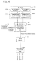
- Fig. 10 is a block diagram illustrating the main configuration relating to the correction of misalignment in the course of bidirectional printing in the first embodiment.
- the P-ROM 43 in the printer 20 includes adjustment number storage areas 202a and 202b and correction value tables 206a and 206b.
- the first misalignment adjustment number is stored in the adjustment number storage area 202a
- the second misalignment adjustment number is stored in the adjustment number storage area 202b.
- Each of the correction value tables 206a and 206b stores the mapping of the misalignment adjustment numbers to the amounts of misalignment (that is, the correction values) of the recording position of the vertical ruled line formed by the backward pass in the test pattern shown in Fig. 8.
- the RAM 44 of the printer 20 stores a computer program having the function of a positional misalignment correction unit 210 to correct the positional misalignment in the course of bidirectional printing.
- the positional misalignment correction unit 210 reads the correction values corresponding to the selected misalignment adjustment numbers from the correction value tables 206a and 206b in the P-ROM 43. On the backward pass, the positional misalignment correction unit 210 receives a signal representing the starting position of the carriage 30 from the position sensor 39 (Fig. 1) and calculates the average of the first correction value and the second correction value as a mean correction value.
- the positional misalignment correction unit 210 supplies a signal for specifying the recording timing of the print head to the head driver 52 according to the mean correction value.
- the head driver 52 sends the driving signal to the actuator chip 94 and adjusts the recording position on the backward pass to the specified recording timing transmitted from the positional misalignment correction unit 210. This causes the recording positions of both the black nozzle array and the color nozzle array to be adjusted with the common mean correction value.
- the black nozzles as well as the color nozzles are used for color printing.
- the correction value which is used to correct the positional misalignment in the course of bidirectional printing, is established using the center nozzle part of the nozzle array as a reference, and actually corrects the positional misalignment in the course of bidirectional printing with the correction value. Even when there is a difference in inclination of the nozzle array in the main scanning direction between the forward pass and the backward pass, this arrangement ensures the adequate correction for the whole nozzle array, thereby improving the print image quality.
- the correction is carried out with the mean of the respective correction values for the color nozzle array and the black nozzle array (that is, the first correction value and the second correction value).
- the correction is carried out with only the correction value for the black nozzle array (that is, the second correction value). This arrangement ensures the optimum corrections in the respective print modes.
- the color nozzles are arrayed in the sub-scanning direction in the sequence of the cyan nozzle group 94C, the magenta nozzle group 94M, and the yellow nozzle group 94Y.
- the central magenta nozzle group 94M is used for printing the test pattern.
- the correction is accordingly made to minimize the misalignment of recording positions of dots with regard to magenta.
- the misalignment of recording positions in magenta is more conspicuous than that in yellow.
- the yellow nozzle group 94Y where the misalignment of recording positions in yellow is relatively inconspicuous, is allocated to one of the end parts that has the greater degree of misalignment of recording positions of dots than the center part.
- the misaligned recording position of the end part is accordingly not prominent.
- This arrangement makes the total misalignment of recording positions of dots sufficiently inconspicuous and thereby prevents deterioration of the image quality.
- the magenta nozzles are used as the representative color nozzle sub-array to print the test pattern.
- the representative color nozzle sub-array is, however, not restricted to the magenta nozzles.
- the cyan nozzles ensure the same effects as long as the cyan nozzles are located within the predetermined range in the neighborhood of the center of the nozzle array.
- the yellow nozzles may also be used as the representative color nozzle sub-array to correct the misalignment of recording positions.
- the representative nozzle sub-array used to print the test pattern includes nozzles located in the part C shown in Fig. 6 among all the nozzles in the nozzle array.
- the representative nozzle sub-array is, however, not restricted to this part C.
- the representative nozzle sub-array may be a sequence of nozzles that includes a specific nozzle closest to the center position along the nozzle array and consists of approximately half of all the nozzles in the nozzle array. More preferably the representative nozzle sub-array is a sequence of nozzles consisting of approximately one third of all the nozzles in the nozzle array.
- the representative nozzle sub-array is not required to have equal nozzles along the length of the nozzle array from the center position of the nozzle array.
- the representative nozzle sub-array may be a group of nozzles that are located within a predetermined range in the neighborhood of the center of the nozzle array. In other words, the representative nozzle sub-array includes the specific nozzle closest to the center position along the nozzle array but does not include end nozzles on either end of the nozzle array.
- the technique of the embodiment carries out the correction with the simple arithmetic mean (average) of the respective correction values of the color nozzle array and the black nozzle array (that is, the first correction value and the second correction value).
- the calculation of the mean correction value is not restricted to this method, but the mean correction value may be a weighted average of the first correction value and the second correction value.
- This procedure may give weights to the first correction value and the second correction value by taking into account the frequency of use of the color inks, yellow, cyan, and magenta, and the black ink, the distance from the center of the nozzle array, and the degree of conspicuousness of the misaligned recording position, and may calculate the weighted average to obtain the mean correction value.
- the technique of the embodiment carries out the correction with the mean of the first correction value and the second correction value in color printing.
- the correction may be carried out with only the correction value for the color nozzle array (that is, the first correction value) in color printing.
- the misalignment of recording positions in the main scanning direction may be corrected in the course of bidirectional printing based on the first and the second correction values, without limitation on the way of the use of the first and the second correction values.
- the procedure of using the mean value of the first correction value and the second correction value as discussed in the above embodiment is suitable for the correction when black nozzles are used in color printing.
- the misalignment of recording positions is corrected in the printing apparatus having the print head unit 60 where one actuator controls 48 nozzles arrayed in the sub-scanning direction as shown in Fig. 3.
- the technique of correcting the misalignment of recording positions according to the present invention is, however, not restricted to the printing apparatus of this structure.
- the technique of the present invention is applicable to another printing apparatus where a plurality of actuators are aligned in the sub-scanning direction and a large number of nozzles Nz are arranged in the sub-scanning direction.
- each head assembly includes a plurality of nozzle units arrayed in the sub-scanning direction.
- the head assemblies 96a through 96d respectively eject the color inks of black (K), cyan (C), magenta (M), and yellow (Y).
- the representative nozzle sub-array consists of nozzles Nzc that are located in a predetermined range in the vicinity of the center of the nozzle array, which extends in the sub-scanning direction on the head assembly.
- the procedure prints the positional misalignment test pattern on the printing medium with the representative nozzle sub-array, determines the correction value, and corrects the misalignment of recording positions with the correction value. Since a long nozzle array extends in the sub-scanning direction, even a minute declination of the nozzle array results in a significant positional misalignment on both ends of the nozzle array.
- the technique of correcting the misalignment of recording positions according to the present invention is especially effective for the printing apparatus of such structure.
- the printing apparatus having such a nozzle arrangement enables a large number of dots to be simultaneously created by one pass of the main scan and accordingly has the advantage of the high printing speed.
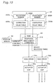
- Fig. 12 is a block diagram illustrating the main configuration relating to the correction of misalignment in the course of bidirectional printing in a second embodiment.
- the difference from the structure shown in Fig. 10 is that an actuator chip 95a causing the black nozzle array to eject the black ink is separate from an actuator chip 95b causing the color nozzle array to eject the cyan, magenta, and yellow inks and that a head driver 52a for driving the actuator chip 95a is separate from a head driver 52b for driving the actuator chip 95b.
- the two head drivers 52a and 52b independently drive the respective actuator chips 95a and 95b.
- the positional misalignment correction unit 210 gives the specified recording timings independently to the respective head drivers 52a and 52b. The positional misalignment in the course of bidirectional printing is accordingly carried out for each actuator chip.
- the feature of the second embodiment is that the correction value is set independently for each actuator chip.
- the arrangement of correcting the positional misalignment for each actuator chip ensures the finer correction with regard to each nozzle group or groups in the same actuator chip, thus further reducing the positional misalignment in the course of bidirectional printing.
- the recording position of dots depends on a variation in ejection speed of ink droplets ejected from the nozzle array. Namely the variation in ejection speed of ink droplets results in shifting the recording position of dots.
- the variation in ejection speed of ink droplets ejected from each nozzle array depends upon a variety of factors given below:
- the ink droplets ejected from the same actuator have a substantially equal ejection speed. In this case, it is preferable to correct the misalignment of recording positions in the main scanning direction with regard to each of nozzle array groups that are driven by different actuator chips respectively.
Landscapes
- Ink Jet (AREA)
- Accessory Devices And Overall Control Thereof (AREA)
- Character Spaces And Line Spaces In Printers (AREA)
- Particle Formation And Scattering Control In Inkjet Printers (AREA)
- Orthopedics, Nursing, And Contraception (AREA)
- Dot-Matrix Printers And Others (AREA)
- Registering, Tensioning, Guiding Webs, And Rollers Therefor (AREA)
Abstract
Description
Claims (9)
- A printing apparatus that carries out bidirectional, reciprocating main scan and prints on a printing medium, the printing apparatus comprising:a print head having a nozzle array that is arranged in a sub-scanning direction and ejects ink droplets to record dots on the printing medium;a memory that stores a correction value, the correction value being used to correct misalignment of recording positions in a main scanning direction on a forward pass and a backward pass of the main scan; anda positional misalignment correction unit that corrects using the correction value the misalignment of recording positions in the main scanning direction occurring in bidirectional printing,wherein the correction value is determined according to correction information that represents a favorable correction state selected based on a positional misalignment test pattern, the positional misalignment test pattern being printed on a printing medium with a representative nozzle sub-array, which is part of the nozzle array and is within a predetermined range around a center of the nozzle array.
- A printing apparatus in accordance with claim 1, wherein the nozzle array comprises:a color nozzle array including a plurality of color nozzles to eject color ink that are arranged in a predetermined sequence in the sub-scanning direction, and a black nozzle array including a plurality of black nozzles to eject black ink that are arranged in a predetermined sequence in the sub-scanning direction, andthe memory stores a first correction value and a second correction value,the first correction value being set for correcting the positional misalignment of recording positions in the main scanning direction on the forward pass and the backward pass of the main scan with regard to a representative color nozzle sub-array, which is part of the color nozzle array and is within a predetermined range around a center of the color nozzle array,the second correction value being set for correcting the positional misalignment of recording positions in the main scanning direction on the forward pass and the backward pass of the main scan with regard to a representative black nozzle sub-array, which is part of the black nozzle array and is within a predetermined range around a center of the black nozzle array.
- A printing apparatus in accordance with claim 2, wherein the positional misalignment correction unit corrects the misalignment of recording positions in the main scanning direction in the bidirectional printing with a mean value of the first correction value and the second correction value.
- A printing apparatus in accordance with claim 2, wherein the positional misalignment correction unit corrects the misalignment of recording positions with the first correction value in a print mode in which the nozzles of the color nozzle array are used.
- A printing apparatus in accordance with claim 2, wherein the positional misalignment correction unit corrects the misalignment of recording positions with the second correction value in a print mode in which the nozzles of the color nozzle array are not used.
- A printing apparatus in accordance with claim 2, wherein the positional misalignment correction unit corrects the misalignment of recording positions using the first correction value with regard to the color nozzle array, and corrects the misalignment of recording positions using the second correction value with regard to the black nozzle array.
- A printing apparatus in accordance with any one of claims 2 through 6, wherein the color nozzle array comprises yellow nozzles for ejecting yellow ink, cyan nozzles for ejecting cyan ink, and magenta nozzles for ejecting magenta ink, and
the representative color nozzle sub-array consists of either of cyan nozzles and magenta nozzles. - In a printing apparatus that comprises a print head having a nozzle array, which is arranged in a sub-scanning direction and ejects ink droplets to record dots on a printing medium, and carries out bidirectional, reciprocating main scan to complete print on the printing medium, a method of correcting misalignment of recording positions of ink droplets in a main scanning direction on a forward pass and a backward pass of the main scan, the method comprising the steps of:(a) printing a positional misalignment test pattern on a printing medium with a representative nozzle sub-array, which is part of the nozzle array and is within a predetermined range around the center of the nozzle array;(b) determining a correction value according to correction information that represents a favorable correction state selected based on the positional misalignment test pattern, the correction value being used to correct the misalignment of recording positions in the main scanning direction on the forward pass and the backward pass of the main scan; and(c) correcting with the correction value the misalignment of recording positions in the main scanning direction in bidirectional printing.
- A recording medium that stores a computer program for causing a computer to correct misalignment of recording positions of ink droplets in a main scanning direction on a forward pass and a backward pass of the main scan, the computer comprising a printing apparatus that includes a print head having a nozzle array which is arranged in a sub-scanning direction and ejects ink droplets to record dots on a printing medium, the printing apparatus carrying out bidirectional, reciprocating main scan to print on the printing medium, the computer program causing the computer to attain the functions of:(a) printing a positional misalignment test pattern on a printing medium with a representative nozzle sub-array, which is part of a nozzle array and is within a predetermined range around the center of the nozzle array;(b) determining a correction value according to correction information that represents a favorable correction state selected based on the positional misalignment test pattern, the correction value being used to correct the misalignment of recording positions in the main scanning direction on the forward pass and the backward pass of the main scan; and(c) correcting with the correction value the misalignment of recording positions in the main scanning direction in bidirectional printing.
Applications Claiming Priority (3)
| Application Number | Priority Date | Filing Date | Title |
|---|---|---|---|
| JP19390399 | 1999-07-08 | ||
| JP19390399A JP3480374B2 (en) | 1999-07-08 | 1999-07-08 | Correction of misalignment of bi-directional printing considering nozzle row inclination |
| PCT/JP2000/004501 WO2001003937A1 (en) | 1999-07-08 | 2000-07-06 | Misregistration correction for bidirectional printing in consideration of inclination of nozzle array |
Publications (3)
| Publication Number | Publication Date |
|---|---|
| EP1112851A1 true EP1112851A1 (en) | 2001-07-04 |
| EP1112851A4 EP1112851A4 (en) | 2003-01-08 |
| EP1112851B1 EP1112851B1 (en) | 2006-05-17 |
Family
ID=16315668
Family Applications (1)
| Application Number | Title | Priority Date | Filing Date |
|---|---|---|---|
| EP00944294A Expired - Lifetime EP1112851B1 (en) | 1999-07-08 | 2000-07-06 | Misregistration correction for bidirectional printing in consideration of inclination of nozzle array |
Country Status (6)
| Country | Link |
|---|---|
| US (2) | US6554387B1 (en) |
| EP (1) | EP1112851B1 (en) |
| JP (1) | JP3480374B2 (en) |
| AT (1) | ATE326349T1 (en) |
| DE (1) | DE60027995T2 (en) |
| WO (1) | WO2001003937A1 (en) |
Cited By (5)
| Publication number | Priority date | Publication date | Assignee | Title |
|---|---|---|---|---|
| EP1120261A4 (en) * | 1999-08-03 | 2002-11-06 | Seiko Epson Corp | OFFSET RESUMPTION FOR BACKWARD PRINTING WITH ERROR REDUCTION BY INFLUENCE OF VERTICAL SCAN |
| EP1764224A1 (en) * | 2005-09-20 | 2007-03-21 | Agfa Graphics N.V. | A method and apparatus for digital printing with preservation of the alignment of printed dots under various printing conditions. |
| CN100355583C (en) * | 2003-02-24 | 2007-12-19 | 星精密株式会社 | Printer and print control method |
| CN101508210B (en) * | 2008-01-24 | 2011-11-09 | 精工爱普生株式会社 | Liquid discharging apparatus |
| CN117207672A (en) * | 2022-06-02 | 2023-12-12 | 深圳市汉森软件股份有限公司 | Intelligent correction method, device, equipment and medium for spray head based on image recognition |
Families Citing this family (85)
| Publication number | Priority date | Publication date | Assignee | Title |
|---|---|---|---|---|
| US6631986B2 (en) * | 1998-12-16 | 2003-10-14 | Silverbrook Research Pty Ltd | Printer transport roller with internal drive motor |
| JP2000296609A (en) | 1999-02-10 | 2000-10-24 | Seiko Epson Corp | Adjustment of recording position deviation in bidirectional printing using reference correction value and relative correction value |
| JP3480374B2 (en) * | 1999-07-08 | 2003-12-15 | セイコーエプソン株式会社 | Correction of misalignment of bi-directional printing considering nozzle row inclination |
| TW523465B (en) * | 2001-02-06 | 2003-03-11 | Olympus Optical Co | Image forming apparatus |
| JP4055380B2 (en) * | 2001-07-27 | 2008-03-05 | 富士ゼロックス株式会社 | Recording position adjustment pattern forming method, image recording position adjusting method, and image recording apparatus |
| JP2003274143A (en) * | 2002-03-15 | 2003-09-26 | Fuji Xerox Co Ltd | Image forming device and method therefor |
| JP2004025507A (en) * | 2002-06-21 | 2004-01-29 | Seiko Epson Corp | Testing device and recording device |
| JP4608847B2 (en) * | 2003-05-01 | 2011-01-12 | セイコーエプソン株式会社 | Liquid ejection apparatus, correction pattern, correction pattern forming method, and liquid ejection system |
| JP4529376B2 (en) * | 2003-05-01 | 2010-08-25 | セイコーエプソン株式会社 | Liquid ejection device, correction pattern, correction pattern forming method, and liquid ejection system |
| US6938975B2 (en) | 2003-08-25 | 2005-09-06 | Lexmark International, Inc. | Method of reducing printing defects in an ink jet printer |
| US7600843B2 (en) * | 2004-05-27 | 2009-10-13 | Silverbrook Research Pty Ltd | Printer controller for controlling a printhead module based on thermal sensing |
| US7275805B2 (en) * | 2004-05-27 | 2007-10-02 | Silverbrook Research Pty Ltd | Printhead comprising different printhead modules |
| US7448707B2 (en) * | 2004-05-27 | 2008-11-11 | Silverbrook Research Pty Ltd | Method of expelling ink from nozzels in groups, starting at outside nozzels of each group |
| US7188928B2 (en) * | 2004-05-27 | 2007-03-13 | Silverbrook Research Pty Ltd | Printer comprising two uneven printhead modules and at least two printer controllers, one of which sends print data to both of the printhead modules |
| US20060067592A1 (en) * | 2004-05-27 | 2006-03-30 | Walmsley Simon R | Configurable image processor |
| US7735944B2 (en) | 2004-05-27 | 2010-06-15 | Silverbrook Research Pty Ltd | Printer comprising two printhead modules and at least two printer controllers |
| US20070083491A1 (en) * | 2004-05-27 | 2007-04-12 | Silverbrook Research Pty Ltd | Storage of key in non-volatile memory |
| US7267417B2 (en) * | 2004-05-27 | 2007-09-11 | Silverbrook Research Pty Ltd | Printer controller for supplying data to one or more printheads via serial links |
| US7390071B2 (en) * | 2004-05-27 | 2008-06-24 | Silverbrook Research Pty Ltd | Printer controller for supplying data to a printhead module having a dropped row |
| US7832842B2 (en) * | 2004-05-27 | 2010-11-16 | Silverbrook Research Pty Ltd | Printer controller for supplying data to a printhead module having interleaved shift registers |
| US7758143B2 (en) * | 2004-05-27 | 2010-07-20 | Silverbrook Research Pty Ltd | Printhead module having nozzle redundancy |
| US20060139387A1 (en) * | 2004-05-27 | 2006-06-29 | Silverbrook Research Pty Ltd | Printer controller for providing data and command via communication output |
| US7517036B2 (en) * | 2004-05-27 | 2009-04-14 | Silverbrook Research Pty Ltd | Printhead module capable of printing a maximum of n channels of print data |
| US7631190B2 (en) * | 2004-05-27 | 2009-12-08 | Silverbrook Research Pty Ltd | Use of variant and base keys with two entities |
| EP1765595B1 (en) * | 2004-05-27 | 2011-03-16 | Silverbrook Research Pty. Ltd | Method for at least partially compensating for errors in ink dot placement due to erroneous rotational displacement |
| US7549715B2 (en) * | 2004-05-27 | 2009-06-23 | Silverbrook Research Pty Ltd | Printer controller for causing expulsion of ink from nozzles in groups, starting at outside nozzles of groups |
| US7757086B2 (en) * | 2004-05-27 | 2010-07-13 | Silverbrook Research Pty Ltd | Key transportation |
| US20060125854A1 (en) * | 2004-05-27 | 2006-06-15 | Silverbrook Research Pty Ltd | Printhead module having two shift registers |
| US7374266B2 (en) | 2004-05-27 | 2008-05-20 | Silverbrook Research Pty Ltd | Method for at least partially compensating for errors in ink dot placement due to erroneous rotational displacement |
| US20060132518A1 (en) * | 2004-05-27 | 2006-06-22 | Silverbrook Research Pty Ltd | Printhead module having interleaved shift registers |
| US7281777B2 (en) * | 2004-05-27 | 2007-10-16 | Silverbrook Research Pty Ltd | Printhead module having a communication input for data and control |
| US20060004829A1 (en) * | 2004-05-27 | 2006-01-05 | Silverbrook Research Pty Ltd | Rolling keys |
| US7290852B2 (en) * | 2004-05-27 | 2007-11-06 | Silverbrook Research Pty Ltd | Printhead module having a dropped row |
| US8011747B2 (en) * | 2004-05-27 | 2011-09-06 | Silverbrook Research Pty Ltd | Printer controller for controlling a printhead with horizontally grouped firing order |
| US7328956B2 (en) * | 2004-05-27 | 2008-02-12 | Silverbrook Research Pty Ltd | Printer comprising a printhead and at least two printer controllers connected to a common input of the printhead |
| US20060132516A1 (en) * | 2004-05-27 | 2006-06-22 | Walmsley Simon R | Printer controller for causing expulsion of ink from nozzles in groups, alternately, starting at outside nozzles of each group |
| US20060164452A1 (en) * | 2004-05-27 | 2006-07-27 | Silverbrook Research Pty Ltd | Printer controller for supplying data to a printhead capable of printing a maximum of n channels of print data |
| US7549718B2 (en) * | 2004-05-27 | 2009-06-23 | Silverbrook Research Pty Ltd | Printhead module having operation controllable on basis of thermal sensors |
| US7281330B2 (en) * | 2004-05-27 | 2007-10-16 | Silverbrook Research Pty Ltd | Method of manufacturing left-handed and right-handed printhead modules |
| US7370932B2 (en) * | 2004-05-27 | 2008-05-13 | Silverbrook Research Pty Ltd | Cartridge having integrated circuit for enabling validation thereof by a mobile device |
| US7243193B2 (en) * | 2004-05-27 | 2007-07-10 | Silverbrook Research Pty Ltd | Storage of program code in arbitrary locations in memory |
| US7266661B2 (en) * | 2004-05-27 | 2007-09-04 | Silverbrook Research Pty Ltd | Method of storing bit-pattern in plural devices |
| US20060092205A1 (en) * | 2004-05-27 | 2006-05-04 | Silverbrook Research Pty Ltd | Printhead module for expelling ink from nozzles in groups, starting at outside nozzles of each group |
| US7557941B2 (en) * | 2004-05-27 | 2009-07-07 | Silverbrook Research Pty Ltd | Use of variant and base keys with three or more entities |
| US20060143454A1 (en) * | 2004-05-27 | 2006-06-29 | Silverbrook Research Pty Ltd | Storage of multiple keys in memory |
| US7252353B2 (en) * | 2004-05-27 | 2007-08-07 | Silverbrook Research Pty Ltd | Printer controller for supplying data to a printhead module having one or more redundant nozzle rows |
| US20060294312A1 (en) * | 2004-05-27 | 2006-12-28 | Silverbrook Research Pty Ltd | Generation sequences |
| JP4599890B2 (en) * | 2004-05-27 | 2010-12-15 | セイコーエプソン株式会社 | Printing apparatus, computer program, and dot formation position deviation correction method |
| US7484831B2 (en) * | 2004-05-27 | 2009-02-03 | Silverbrook Research Pty Ltd | Printhead module having horizontally grouped firing order |
| US7093989B2 (en) * | 2004-05-27 | 2006-08-22 | Silverbrook Research Pty Ltd | Printer comprising two uneven printhead modules and at least two printer controllers, one which spends print data to the other |
| US7427117B2 (en) * | 2004-05-27 | 2008-09-23 | Silverbrook Research Pty Ltd | Method of expelling ink from nozzles in groups, alternately, starting at outside nozzles of each group |
| US7314261B2 (en) * | 2004-05-27 | 2008-01-01 | Silverbrook Research Pty Ltd | Printhead module for expelling ink from nozzles in groups, alternately, starting at outside nozzles of each group |
| US7607757B2 (en) * | 2004-05-27 | 2009-10-27 | Silverbrook Research Pty Ltd | Printer controller for supplying dot data to at least one printhead module having faulty nozzle |
| US7377609B2 (en) * | 2004-05-27 | 2008-05-27 | Silverbrook Research Pty Ltd | Printer controller for at least partially compensating for erroneous rotational displacement |
| US7866778B2 (en) * | 2004-05-27 | 2011-01-11 | Silverbrook Research Pty Ltd | Printhead module having nozzle redundancy for faulty nozzle tolerance |
| JP4604570B2 (en) * | 2004-06-25 | 2011-01-05 | セイコーエプソン株式会社 | Adjustment pattern forming method, adjustment pattern, printing method, and printing apparatus |
| JP4507724B2 (en) * | 2004-07-01 | 2010-07-21 | セイコーエプソン株式会社 | Printing apparatus, computer program, printing system, and printing method |
| US7374269B2 (en) * | 2004-09-30 | 2008-05-20 | Lexmark International, Inc. | Methods for determining unidirectional print direction for improved quality |
| JP4434112B2 (en) * | 2004-12-28 | 2010-03-17 | セイコーエプソン株式会社 | Printing apparatus, printing apparatus control program, and printing apparatus control method |
| JP4606949B2 (en) * | 2005-03-31 | 2011-01-05 | 富士フイルム株式会社 | Drawing apparatus and drawing method |
| JP4717535B2 (en) * | 2005-07-08 | 2011-07-06 | キヤノン株式会社 | Recording apparatus and tilt correction method |
| US7549721B2 (en) * | 2005-08-31 | 2009-06-23 | Seiko Epson Corporation | Printing method, printing system and method for determining correction value |
| JP5075364B2 (en) * | 2006-06-20 | 2012-11-21 | 理想科学工業株式会社 | Image recording apparatus and image recording method |
| JP5352951B2 (en) * | 2006-10-03 | 2013-11-27 | 富士ゼロックス株式会社 | Droplet ejection device, control method for droplet ejection device, and control program for droplet ejection device |
| JP4518073B2 (en) * | 2006-12-21 | 2010-08-04 | セイコーエプソン株式会社 | Liquid ejection device and liquid ejection method |
| US7654630B2 (en) * | 2007-03-09 | 2010-02-02 | Lexmark International, Inc. | Method for decreasing sensitivity to errors in an imaging apparatus |
| JP2009006677A (en) * | 2007-06-29 | 2009-01-15 | Canon Inc | Recording device |
| JP4967893B2 (en) * | 2007-07-25 | 2012-07-04 | セイコーエプソン株式会社 | Method for resetting driving voltage of liquid ejecting apparatus and liquid ejecting apparatus |
| JP2009137251A (en) * | 2007-12-10 | 2009-06-25 | Seiko Epson Corp | Liquid ejection method and liquid ejection apparatus |
| JP5151445B2 (en) * | 2007-12-14 | 2013-02-27 | セイコーエプソン株式会社 | Liquid ejection method and liquid ejection apparatus |
| JP5396753B2 (en) * | 2008-06-23 | 2014-01-22 | 株式会社リコー | Image forming apparatus |
| JP5037468B2 (en) * | 2008-09-30 | 2012-09-26 | 富士フイルム株式会社 | Dot position measuring method, apparatus and program |
| JP5564819B2 (en) * | 2009-04-03 | 2014-08-06 | セイコーエプソン株式会社 | Correction value calculation method and fluid ejection device manufacturing method |
| JP5436388B2 (en) * | 2010-10-05 | 2014-03-05 | キヤノン株式会社 | Image processing apparatus, image processing method, and image recording apparatus |
| JP6291777B2 (en) * | 2012-12-05 | 2018-03-14 | 株式会社リコー | Image forming apparatus, test pattern forming method, and program |
| US8613493B1 (en) * | 2013-01-25 | 2013-12-24 | Eastman Kodak Company | Positioning a mobile apparatus for adjacent printing swaths |
| JP6364969B2 (en) * | 2014-05-30 | 2018-08-01 | ブラザー工業株式会社 | Inkjet printer |
| JP6700652B2 (en) | 2014-05-30 | 2020-05-27 | ブラザー工業株式会社 | Inkjet printer |
| CN104228370A (en) * | 2014-08-25 | 2014-12-24 | 深圳怡化电脑股份有限公司 | Return difference measuring method and ruler for needle printer |
| JP6672830B2 (en) * | 2016-01-25 | 2020-03-25 | セイコーエプソン株式会社 | Printing apparatus and printing method |
| US10960695B2 (en) * | 2018-08-07 | 2021-03-30 | Canon Kabushiki Kaisha | Printing apparatus and correction method therefor |
| JP7354698B2 (en) * | 2018-09-27 | 2023-10-03 | 株式会社リコー | Liquid discharge device, liquid discharge method, and program |
| WO2022093194A1 (en) * | 2020-10-27 | 2022-05-05 | Hewlett-Packard Development Company, L.P. | Test patterns |
| CN117124731A (en) * | 2022-05-18 | 2023-11-28 | 深圳市汉森软件股份有限公司 | Printing method, calibration method and related device and equipment for spray head calibration chart |
| CN117124730A (en) * | 2022-05-18 | 2023-11-28 | 深圳市汉森软件股份有限公司 | Automatic spray head calibration method, device, equipment and medium based on machine vision |
Family Cites Families (15)
| Publication number | Priority date | Publication date | Assignee | Title |
|---|---|---|---|---|
| JPH0569625A (en) | 1991-09-11 | 1993-03-23 | Seiko Epson Corp | Serial printer device |
| US5455610A (en) * | 1993-05-19 | 1995-10-03 | Xerox Corporation | Color architecture for an ink jet printer with overlapping arrays of ejectors |
| JP3332478B2 (en) * | 1993-06-22 | 2002-10-07 | キヤノン株式会社 | Recording device and recording method |
| JPH0725101A (en) | 1993-07-09 | 1995-01-27 | Canon Inc | Print control method |
| US6367903B1 (en) * | 1997-02-06 | 2002-04-09 | Hewlett-Packard Company | Alignment of ink dots in an inkjet printer |
| JP3560305B2 (en) * | 1997-03-28 | 2004-09-02 | キヤノン株式会社 | Recording device and check pattern recording method |
| JP3858344B2 (en) * | 1997-05-23 | 2006-12-13 | ブラザー工業株式会社 | Printing method and printing apparatus |
| US6310637B1 (en) * | 1997-07-31 | 2001-10-30 | Seiko Epson Corporation | Method of printing test pattern and printing apparatus for the same |
| JP2000062156A (en) | 1998-08-26 | 2000-02-29 | Oki Data Corp | Liquid jet recording apparatus and adjustment method thereof |
| JP2000127360A (en) * | 1998-10-23 | 2000-05-09 | Canon Inc | Recording device and print position correction method |
| JP2000127370A (en) | 1998-10-27 | 2000-05-09 | Canon Inc | Arrangement method of optical sensor, print alignment method using the optical sensor, and printing apparatus |
| JP2000141624A (en) | 1998-11-11 | 2000-05-23 | Canon Inc | Printing apparatus and printing method |
| US6315382B1 (en) * | 1998-12-15 | 2001-11-13 | Hewlett-Packard Company | Printer drive roller positioning |
| EP1029673B1 (en) * | 1999-02-18 | 2006-06-28 | Hewlett-Packard Company, A Delaware Corporation | A correction system for droplet placement errors in the scan axis in inkjet printers |
| JP3480374B2 (en) * | 1999-07-08 | 2003-12-15 | セイコーエプソン株式会社 | Correction of misalignment of bi-directional printing considering nozzle row inclination |
-
1999
- 1999-07-08 JP JP19390399A patent/JP3480374B2/en not_active Expired - Fee Related
-
2000
- 2000-07-06 EP EP00944294A patent/EP1112851B1/en not_active Expired - Lifetime
- 2000-07-06 DE DE60027995T patent/DE60027995T2/en not_active Expired - Lifetime
- 2000-07-06 AT AT00944294T patent/ATE326349T1/en not_active IP Right Cessation
- 2000-07-06 WO PCT/JP2000/004501 patent/WO2001003937A1/en not_active Ceased
- 2000-07-06 US US09/786,335 patent/US6554387B1/en not_active Expired - Lifetime
-
2002
- 2002-11-29 US US10/306,223 patent/US6726303B2/en not_active Expired - Lifetime
Cited By (7)
| Publication number | Priority date | Publication date | Assignee | Title |
|---|---|---|---|---|
| EP1120261A4 (en) * | 1999-08-03 | 2002-11-06 | Seiko Epson Corp | OFFSET RESUMPTION FOR BACKWARD PRINTING WITH ERROR REDUCTION BY INFLUENCE OF VERTICAL SCAN |
| US6527359B1 (en) | 1999-08-03 | 2003-03-04 | Seiko Epson Corporation | Misregistration correction for bidirectional printing with reduced influence of error due to vertical scanning |
| CN100355583C (en) * | 2003-02-24 | 2007-12-19 | 星精密株式会社 | Printer and print control method |
| EP1764224A1 (en) * | 2005-09-20 | 2007-03-21 | Agfa Graphics N.V. | A method and apparatus for digital printing with preservation of the alignment of printed dots under various printing conditions. |
| WO2007039447A1 (en) * | 2005-09-20 | 2007-04-12 | Agfa Graphics Nv | A method and apparatus for digital printing with preservation of the alignment of printed dots under various printing conditions |
| CN101508210B (en) * | 2008-01-24 | 2011-11-09 | 精工爱普生株式会社 | Liquid discharging apparatus |
| CN117207672A (en) * | 2022-06-02 | 2023-12-12 | 深圳市汉森软件股份有限公司 | Intelligent correction method, device, equipment and medium for spray head based on image recognition |
Also Published As
| Publication number | Publication date |
|---|---|
| WO2001003937A1 (en) | 2001-01-18 |
| US20030085937A1 (en) | 2003-05-08 |
| US6726303B2 (en) | 2004-04-27 |
| EP1112851B1 (en) | 2006-05-17 |
| DE60027995D1 (en) | 2006-06-22 |
| DE60027995T2 (en) | 2007-04-19 |
| EP1112851A4 (en) | 2003-01-08 |
| JP3480374B2 (en) | 2003-12-15 |
| ATE326349T1 (en) | 2006-06-15 |
| US6554387B1 (en) | 2003-04-29 |
| JP2001018375A (en) | 2001-01-23 |
Similar Documents
| Publication | Publication Date | Title |
|---|---|---|
| EP1112851B1 (en) | Misregistration correction for bidirectional printing in consideration of inclination of nozzle array | |
| JP3245957B2 (en) | Ink jet recording apparatus and recording method | |
| EP0995607B1 (en) | Printing apparatus and method for correcting print positions | |
| JP4074414B2 (en) | Adjusting the recording position misalignment during bidirectional printing where the correction value is changed between monochrome printing and color printing | |
| JP3654141B2 (en) | Determination of the adjustment value of the recording position deviation during printing using two types of inspection patterns | |
| EP1120261B1 (en) | Misregistration correction for bidirectional printing with reduced influence of error due to vertical scanning | |
| US8517490B2 (en) | Printing apparatus and printing method for determining a driving order in accordance with a displacement of print nozzles | |
| US6464321B1 (en) | Printing apparatus having function of adjusting positional misalignment of dots | |
| JPH09314825A (en) | Printing method for compensating minute band-like pattern | |
| EP1025999B1 (en) | Printing apparatus, method of printing, and recording medium | |
| JP3567798B2 (en) | Printing apparatus, printing method, and recording medium | |
| JPH1148587A (en) | Test dot recording method and printer | |
| JP2007015260A (en) | Recording apparatus and control method thereof | |
| JP2010280205A (en) | Recording apparatus and recording position adjusting method | |
| EP1221380B1 (en) | Determining adjustment value for recording position deviation at printing using a plurality of kinds of inspecting patterns | |
| JP4284942B2 (en) | Printing apparatus, computer program, computer system, and correction pattern manufacturing method | |
| JP2008000922A (en) | Image processing method and inkjet recording apparatus | |
| US6464323B2 (en) | Registration adjusting method of ink-jet printing apparatus | |
| JP4035962B2 (en) | Printing that adjusts the dot position by shaping the drive signal | |
| JP2001334654A (en) | Adjustment of formation position shift between dots formed at different timings | |
| US20010052915A1 (en) | Ink jet printer for reducing dot shift | |
| US7306306B2 (en) | Inkjet recording method and inkjet recording apparatus | |
| JP2001063022A (en) | Correction of dot position misalignment in bidirectional printing that records one pixel with multiple types of ink droplets | |
| JP2004188627A (en) | Inkjet recording device | |
| JP2006315322A (en) | Recording device |
Legal Events
| Date | Code | Title | Description |
|---|---|---|---|
| PUAI | Public reference made under article 153(3) epc to a published international application that has entered the european phase |
Free format text: ORIGINAL CODE: 0009012 |
|
| 17P | Request for examination filed |
Effective date: 20010320 |
|
| AK | Designated contracting states |
Kind code of ref document: A1 Designated state(s): AT BE CH CY DE DK ES FI FR GB GR IE IT LI LU MC NL PT SE |
|
| AX | Request for extension of the european patent |
Free format text: AL;LT;LV;MK;RO;SI |
|
| A4 | Supplementary search report drawn up and despatched |
Effective date: 20021125 |
|
| AK | Designated contracting states |
Kind code of ref document: A4 Designated state(s): AT BE CH CY DE DK ES FI FR GB GR IE IT LI LU MC NL PT SE |
|
| RIC1 | Information provided on ipc code assigned before grant |
Free format text: 7B 41J 2/21 A, 7B 41J 29/393 B |
|
| 17Q | First examination report despatched |
Effective date: 20030402 |
|
| GRAP | Despatch of communication of intention to grant a patent |
Free format text: ORIGINAL CODE: EPIDOSNIGR1 |
|
| GRAC | Information related to communication of intention to grant a patent modified |
Free format text: ORIGINAL CODE: EPIDOSCIGR1 |
|
| GRAS | Grant fee paid |
Free format text: ORIGINAL CODE: EPIDOSNIGR3 |
|
| GRAA | (expected) grant |
Free format text: ORIGINAL CODE: 0009210 |
|
| AK | Designated contracting states |
Kind code of ref document: B1 Designated state(s): AT BE CH CY DE DK ES FI FR GB GR IE IT LI LU MC NL PT SE |
|
| PG25 | Lapsed in a contracting state [announced via postgrant information from national office to epo] |
Ref country code: NL Free format text: LAPSE BECAUSE OF FAILURE TO SUBMIT A TRANSLATION OF THE DESCRIPTION OR TO PAY THE FEE WITHIN THE PRESCRIBED TIME-LIMIT Effective date: 20060517 Ref country code: AT Free format text: LAPSE BECAUSE OF FAILURE TO SUBMIT A TRANSLATION OF THE DESCRIPTION OR TO PAY THE FEE WITHIN THE PRESCRIBED TIME-LIMIT Effective date: 20060517 Ref country code: CH Free format text: LAPSE BECAUSE OF FAILURE TO SUBMIT A TRANSLATION OF THE DESCRIPTION OR TO PAY THE FEE WITHIN THE PRESCRIBED TIME-LIMIT Effective date: 20060517 Ref country code: FI Free format text: LAPSE BECAUSE OF FAILURE TO SUBMIT A TRANSLATION OF THE DESCRIPTION OR TO PAY THE FEE WITHIN THE PRESCRIBED TIME-LIMIT Effective date: 20060517 Ref country code: BE Free format text: LAPSE BECAUSE OF FAILURE TO SUBMIT A TRANSLATION OF THE DESCRIPTION OR TO PAY THE FEE WITHIN THE PRESCRIBED TIME-LIMIT Effective date: 20060517 Ref country code: LI Free format text: LAPSE BECAUSE OF FAILURE TO SUBMIT A TRANSLATION OF THE DESCRIPTION OR TO PAY THE FEE WITHIN THE PRESCRIBED TIME-LIMIT Effective date: 20060517 |
|
| REG | Reference to a national code |
Ref country code: GB Ref legal event code: FG4D |
|
| REG | Reference to a national code |
Ref country code: CH Ref legal event code: EP |
|
| REG | Reference to a national code |
Ref country code: IE Ref legal event code: FG4D |
|
| REF | Corresponds to: |
Ref document number: 60027995 Country of ref document: DE Date of ref document: 20060622 Kind code of ref document: P |
|
| PG25 | Lapsed in a contracting state [announced via postgrant information from national office to epo] |
Ref country code: IE Free format text: LAPSE BECAUSE OF NON-PAYMENT OF DUE FEES Effective date: 20060706 |
|
| PG25 | Lapsed in a contracting state [announced via postgrant information from national office to epo] |
Ref country code: MC Free format text: LAPSE BECAUSE OF NON-PAYMENT OF DUE FEES Effective date: 20060731 |
|
| PG25 | Lapsed in a contracting state [announced via postgrant information from national office to epo] |
Ref country code: SE Free format text: LAPSE BECAUSE OF FAILURE TO SUBMIT A TRANSLATION OF THE DESCRIPTION OR TO PAY THE FEE WITHIN THE PRESCRIBED TIME-LIMIT Effective date: 20060817 Ref country code: DK Free format text: LAPSE BECAUSE OF FAILURE TO SUBMIT A TRANSLATION OF THE DESCRIPTION OR TO PAY THE FEE WITHIN THE PRESCRIBED TIME-LIMIT Effective date: 20060817 |
|
| PG25 | Lapsed in a contracting state [announced via postgrant information from national office to epo] |
Ref country code: ES Free format text: LAPSE BECAUSE OF FAILURE TO SUBMIT A TRANSLATION OF THE DESCRIPTION OR TO PAY THE FEE WITHIN THE PRESCRIBED TIME-LIMIT Effective date: 20060828 |
|
| PG25 | Lapsed in a contracting state [announced via postgrant information from national office to epo] |
Ref country code: PT Free format text: LAPSE BECAUSE OF FAILURE TO SUBMIT A TRANSLATION OF THE DESCRIPTION OR TO PAY THE FEE WITHIN THE PRESCRIBED TIME-LIMIT Effective date: 20061017 |
|
| NLV1 | Nl: lapsed or annulled due to failure to fulfill the requirements of art. 29p and 29m of the patents act | ||
| REG | Reference to a national code |
Ref country code: CH Ref legal event code: PL |
|
| ET | Fr: translation filed | ||
| PLBE | No opposition filed within time limit |
Free format text: ORIGINAL CODE: 0009261 |
|
| STAA | Information on the status of an ep patent application or granted ep patent |
Free format text: STATUS: NO OPPOSITION FILED WITHIN TIME LIMIT |
|
| 26N | No opposition filed |
Effective date: 20070220 |
|
| PG25 | Lapsed in a contracting state [announced via postgrant information from national office to epo] |
Ref country code: GR Free format text: LAPSE BECAUSE OF FAILURE TO SUBMIT A TRANSLATION OF THE DESCRIPTION OR TO PAY THE FEE WITHIN THE PRESCRIBED TIME-LIMIT Effective date: 20060818 |
|
| PG25 | Lapsed in a contracting state [announced via postgrant information from national office to epo] |
Ref country code: LU Free format text: LAPSE BECAUSE OF NON-PAYMENT OF DUE FEES Effective date: 20060706 |
|
| PG25 | Lapsed in a contracting state [announced via postgrant information from national office to epo] |
Ref country code: CY Free format text: LAPSE BECAUSE OF FAILURE TO SUBMIT A TRANSLATION OF THE DESCRIPTION OR TO PAY THE FEE WITHIN THE PRESCRIBED TIME-LIMIT Effective date: 20060517 |
|
| REG | Reference to a national code |
Ref country code: FR Ref legal event code: PLFP Year of fee payment: 16 |
|
| REG | Reference to a national code |
Ref country code: FR Ref legal event code: PLFP Year of fee payment: 17 |
|
| PGFP | Annual fee paid to national office [announced via postgrant information from national office to epo] |
Ref country code: FR Payment date: 20160613 Year of fee payment: 17 |
|
| PGFP | Annual fee paid to national office [announced via postgrant information from national office to epo] |
Ref country code: IT Payment date: 20160720 Year of fee payment: 17 Ref country code: DE Payment date: 20160628 Year of fee payment: 17 Ref country code: GB Payment date: 20160706 Year of fee payment: 17 |
|
| REG | Reference to a national code |
Ref country code: DE Ref legal event code: R119 Ref document number: 60027995 Country of ref document: DE |
|
| GBPC | Gb: european patent ceased through non-payment of renewal fee |
Effective date: 20170706 |
|
| REG | Reference to a national code |
Ref country code: FR Ref legal event code: ST Effective date: 20180330 |
|
| PG25 | Lapsed in a contracting state [announced via postgrant information from national office to epo] |
Ref country code: GB Free format text: LAPSE BECAUSE OF NON-PAYMENT OF DUE FEES Effective date: 20170706 Ref country code: DE Free format text: LAPSE BECAUSE OF NON-PAYMENT OF DUE FEES Effective date: 20180201 |
|
| PG25 | Lapsed in a contracting state [announced via postgrant information from national office to epo] |
Ref country code: FR Free format text: LAPSE BECAUSE OF NON-PAYMENT OF DUE FEES Effective date: 20170731 |
|
| PG25 | Lapsed in a contracting state [announced via postgrant information from national office to epo] |
Ref country code: IT Free format text: LAPSE BECAUSE OF NON-PAYMENT OF DUE FEES Effective date: 20170706 |