-
The present invention relates to a bent section rail of
subrack for electronic components and to a subrack for
electronic components comprising said bent section rails.
-
The rail, considered for the scope of the present
invention, is of the type incorporating fastening systems
for the installation of electronic cards, located inside
the subrack for electronic components that can
advantageously be mounted in cabinets for electronic
components or the like.
-
The rails commonly used in the field of electronics are
usually made with extruded sections in which guides and
grooves integral to said fastening systems are formed.
Usually, inside a front guide of said extruded section, a
fastening strip is inserted, having a plurality of threaded
openings, spaced with a minimal pitch, apt to be engaged by
conventional bolts and screws for mounting an electronic
card in the desired position with respect to the rail
extension, and therefore to the subrack.
-
Although providing satisfactory card mounting flexibility
and subrack sturdiness, this system requires an high number
of machining steps, in order to obtain the right extruded
section profile; the required surface finishing of the
components that is essential to ensure a conduction
continuity in the mounted subrack; and all the constructive
details that are required for mounting the rail in a
subrack.
-
The fulfilment of all those requirements implies a higher
complexity in the manufacturing processes of said rails,
and, among other consequences, an increased cost thereof.
-
In order to partially overcome these drawbacks, rails
obtained by a plate have been adopted, consisting of a
sheet metal, bent so as to assume the boxed shape of an
elongated parallelepiped. This technique, although
simplifying the manufacturing process, required the
addition of fastening systems for electronic cards as a
further machining step, leading to fastening systems
implying a specific and non flexible electronic card
mounting standard.
-
Therefore, not allowing the manufacture of rails of a
highly flexible use and satisfactory overall sturdiness,
this manufacturing technique has not been widely adopted,
remaining confined to niche products.
-
The technical problem underlying the present invention is
that of providing a bent section rail of subracks for
electronic components, allowing to overcome the drawbacks
mentioned with reference to the known art.
-
Such problem is overcome by a bent section rail as
disclosed above, characterised in that it comprises:
- a plate bent in an elongated parallelepipedal, boxed
shape, defining a inner channel, so that the rail has a
front wall connected to a base wall, developed lengthwise
with respect to the rail;
- a fastening guide, formed in the inner channel along
said front wall and defined by bent portions of said
plate;
- a plurality of first fastening openings, formed in said
front wall; and
- a fastening strip, apt to be inserted and locked inside
said fastening guide, adjacently to the front wall,
having a plurality of second fastening openings located
in a position to correspond to the respective first
fastening openings, in such a way to embody a fastening
seat therewith.
-
The main advantage of the rail according to the present
invention lies in that it allows a high flexibility for
mounting cards on different positions, matched with
structural sturdiness and modularity of the components
constituting the subrack.
-
The subrack for electronic components comprising the rails
according to the invention has a simple construction,
providing a limited number of components.
-
The present invention will hereinafter be described
according to two preferred embodiments thereof, given by
way of example and not for limitative purposes with
reference to the annexed drawings, wherein:
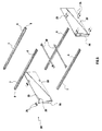
- figure 1 is a partially sectional perspective view of a
first embodiment of a rail of subracks for electronic
components according to the invention, preset for a front
positioning thereof in a subrack for electronic
components;
- figure 2 is a partially sectional perspective view of
the rail of figure 1, preset for a rear positioning
thereof;
- figure 3 is a cross section of the rail of figure 1
along the section line C-C;
- figure 4 is a cross section of the rail of figure 2
along the section line B-B;
- figure 5 is a partially sectional and exploded
perspective view of a subrack for electronic components
incorporating the rail of figure 1;
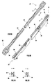
- figures 6a and 6b are partially sectional perspective
views of a detail of a subrack incorporating a rail
according to the present invention, according to two
different embodiments thereof;
- figures 7a and 7b are detailed cross sections of a
detail shown in Figs. 6a, 6b, along D-D and E-E section
lines, respectively;
- figure 8 is a perspective view of the subrack of figure
5, mounted and operational;
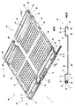
- figure 9 is a perspective and partially sectional view
of a second embodiment of a rail of subracks for
electronic components according to the invention;
- figure 10 is a cross section of the rail of figure 5,
along a section line A-A; and
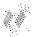
- figure 11 is a partially sectional and exploded
perspective view of a subrack for electronic components
incorporating the rail of figure 9.
-
With reference to figures 1 to 4, a bent section rail of
subracks for electronic components is indicated 1. It is of
the type used in subracks for electronic components, i.e.,
those subracks destined to house electronic cards aligned
inside the subrack, vertically juxtaposed and fastened to
the subrack at the front access side, upperly and lowerly
delimited just by said rails. The ends of a front strap of
the card are fastened to the rails, e.g. with screws.
-
Therefore, said rails are of the type comprising fastening
systems for electronic cards of the specified type.
-
The rail 1 has a flattened and elongated boxed
parallelepipedal shape, developing along a main direction
and identifying a front wall 2, a rear wall 3,
corresponding to the longitudinal faces with a reduced
thickness and developing lengthwise with respect to the
rail 1; connected by a first and a second base wall 4, 5;
end 6; and a inner channel ideally delimited by said walls
2, 3, 4, 5.
-
According to the present embodiment, said rail 1 comprises
a bent plate that embodies and defines the walls 2, 3, 4, 5
of said rail 1.
-
Said plate is a galvanised steel sheet, preferably of a 1.5
mm thickness. It is mechanically cold bent to have a 0.6 mm
bend radius.
-
In particular, the rail 1 has a C-shaped section and
comprises said front wall 2 connected to the first base
wall 4, in turn connected to the rear wall 3. The front
wall 2 and the rear wall 3 have a 90° bending to define a
front and a rear runway in the rail 1, further defining
said second base wall 5 that is centrally opened.
-
At the front runway, the rail 1 comprises a fastening guide
8 that therefore is obtained in the inner channel 7. The
fastening guide is adjacent to the front wall 2, the former
being precisely delimited by the face thereof internal to
the rail 1.
-
At the base wall 4, the rail 1 comprises a plurality of
tongues 9 belonging to the plate and advantageously
obtained by punching, so as to bend them internally to the
inner channel 7 to delimit said fastening guide 8.
-
The rail 1 comprises a plurality of first fastening
openings 10, in particular circular holes, formed e.g. by
cold forging.
-
Said first openings 10 are sequentially located along said
front wall 2, evenly spaced according to a minimal pitch.
-
Further, the rail 1 comprises an attachment, physically
distinct therefrom but functionally connected thereto,
consisting of a fastening strip 11, i.e. a stiff metal
strip apt to be inserted inside said fastening guide 8 and
to be locked therein, having transversal dimensions
realising a minimal sliding clearance inside of the guide
8.
-
Thus, the fastening strip 11 is located adjacently to the
front wall 2, in particular to the inner face thereof. It
has a plurality of second fastening openings 12 that are
located in a position to correspond to the respective first
fastening openings 10, when the fastening strip 11 is
locked inside the fastening guide 8. For this purpose, the
second openings 12 are sequentially located along the
fastening strip 11, evenly spaced according to the same
minimal pitch of the first openings 10.
-
Thus, together the first fastening openings 10 and the
respective second fastening openings 12 are apt to embody a
fastening seat 10, 12.
-
Even the second fastening openings 12 are circular holes,
in the present embodiment having a slightly shorter
diameter than that of the first fastening openings 10.
Further, the second openings have a counterthread onto the
inner surface thereof, for fastening screw means inside of
the fastening seat 10, 12.
-
At the first base wall 4 thereof, i.e. the upperly
positioned one, the rail 1, has a plurality of third
fastening openings 13, sequentially located on a row
developing lengthwise with respect to the rail.
-
Alike the previous ones, also the third openings 13 are
obtained by steel sheet cold forging prior to the bending
and galvanising steps. They are evenly spaced with a
minimal pitch, and conjugate with the respective third
openings 13 of a complementary rail 1 (Fig. 3), realising
an even spacing perpendicularly to the development of the
rails 1.
-
The object of the third openings 13 and of the respective
even spacing will be made apparent hereinafter.
-
The rail 1, at the ends 6 thereof, comprises a cap 14
belonging to the sheet metal, connected to the first base
wall 4 and with a 90° bending, closing the inner channel 7.
-
The cap 14 is truncated at the insertion guide 8, and it
constitutes, with the edges of the base walls 4, 5 and the
edge of the front wall 2, a insertion slot 15 of the
fastening strip 11.
-
Overall, the front wall 2, the base walls 4, 5, the tongues
9 and the caps 14 globally embody bent plate portions
defining the fastening guide 8.
-
End holes 16, apt to house an assembling device, e.g.
rivets, that will be disclosed hereinafter, are obtained in
the caps 14. The rail 1 has a dowel 17 centrally notched in
the respective cap 14, not bent therewith as it belongs to
the first base wall 4.
-
In Figures 1, 2, so as in figures 3 and 4, the mutual
positioning of rails 1 apt to be assembled at an upper or
lower face of a subrack 20, shown in an exploded view in
Figure 5 and assembled in Figure 8.
-
In Figure 1 a first rail apt to be positioned at the access
side 21 of the subrack 20 is shown, whereas a second rear
rail is shown in figure 2. The first rail has said
fastening strip 11 inserted inside the respective fastening
guide 8, whereas the second rail is not provided with it.
Anyhow, the first base walls 4 are upturned.
-
The assembling of the subrack 20 will hereinafter be
illustrated with reference to Figure 5.
-
The subrack 20 is apt to have a flattened parallelepipedal
shape, with a greater longitudinal development lengthwise
the rails 4, a front access side 21 opened at a narrower
longitudinal face, a card insertion depth from said front
face to the respective rear face, and end faces.
-
It comprises four rails 1, a pair of front rails 1 with the
respective fastening strips (not shown) inserted and
another pair of rear rails 1, each rail 1 being located at
the longitudinal corners of the subrack 20.
-
The rails 4 are mutually fastened by rectangular plates 22
located at the end faces of the subrack 20. The plates 22
comprise pairs of counterholes 23, located at the end holes
16 and apt to constitute with the latter a housing seat of
an assembling device, i.e. the rivets 24. Furthermore,
between each pair of counterholes 23 the plate 22 has a
slot 25 apt to be engaged by said dowel 17.
-
At the frontally positioned edge of the plate 22, the plate
itself has a further drilled fastening strip 26, for
assembling the subrack 20 inside of a cabinet for
electronic components.
-
In order to ease the assembling of the subrack 20, the
plates 22 are symmetrical with respect to a median axis,
concordant to the direction of insertion of the electronic
cards.
-
Prior to fastening the plates 22 to the rails 1, it is
necessary to position the respective fastening strips 11,
which will be found correctly locked in place once the
assembly of the plates 22 is carried out, taking into
account that the rails 1 and the fastening strips 11 are of
equal length, thus embodying the fastening seats 10, 12.
-
By connecting the plates 22 to the rails 1, the subrack 20
is structurally assembled. In order to allow the insertion
of the electronic cards, indicated with S in figure 8, the
adoption of an additional component of the subrack 20
becomes necessary: the removable insertion runways 30
(Figs. 6a, 6b, 7a, 7b).
-
Said movable runway 30 is preset onto a fluted rod 31,
provided with longitudinal ribs 32 delimiting said runway
30.
-
The runways 30 are apt to receive the lower and upper edges
of the electronic cards during the assembling thereof
inside of the subrack 20. For this purpose, the runways 30
have an extension such as to allow the connection of
opposed rails 1 located onto the access side 21 and on the
opposite side of the subrack 20.
-
Moreover, the rod 31 has, at the ends thereof, coupling
means 33, comprising an expanded section 34 from which a
pair of pins overhang: particularly, a first pin 35 and a
second ratchet pin 36, apt to fix in the receiving seat
thereof.
-
Then the rods 31 are located with the pins 35, 36 inserted
in the respective third fastening opening 13. The distance
between centres of the pins 35, 36 substantially equals the
pitch between said third openings 13.
-
Two alternative models of the rod 31, suitable for
assembling cards according to different standards are shown
in Figs. 6a, 6b, 7a, 7b.
-
Therefore, in order to carry out the insertion of the card
S, once the subrack 20 is mounted and assembled in its own
cabinet, a movable runway 30 is applied at the bottom
thereof, plus an optional and additional movable runway at
the top thereof, thus creating a single or double
invitation to the insertion.
-
Once the card S is inserted up to the pin-plug coupling
(not shown) usually located at the rear of the subrack 20,
the ends S2 of the strap S1 are fastened at the preselected
fastening seats 10, 12, made in the respective front rails
1.
-
It is apparent that the above disclosed subrack 20 merely
consists of two components: the rails 1 and the plates 22;
plus a pair of attachments: the fastening strip 11 and the
movable runways 30, plus assembling devices with
conventional fastening means like rivets, bolts and screws,
ratchet pins, etc..
-
Those components are: the rails 1 to parallelepipedally
shape the subrack 20, likewise plates 22, plus assembling
means that, in the present embodiment, are the rivets 24.
-
The rails and the plates can be assembled in any position.
Hence, the subrack is remarkably easy to assemble and it
can be provided to the users as an assembly kit.
-
Furthermore, the above described rail 1 is obtained from a
single sheet metal suitably trimmed and subjected to cold
forging, punching, cold bending and galvanising steps in
order to attain the finished product, i.e. the rail 1.
-
The hereto disclosed rails and subrack relate to a subrack
type lacking the shielding plane separating the individual
subrack from other subracks stacked inside a cabinet for
electronic components.
-
With reference to figures 9 to 11, a second embodiment of a
rail according to the present invention will hereinafter be
disclosed, incorporated in a rail-shielding plane set,
indicated with 40 in the Figures, in which components
equivalent to the ones hereto described shall be referred
to using the same number references.
-
The assembly 40, in galvanised steel sheet, has a
rectangular shielding plane 41, of a foraminated type and
obtained from a single metallic conductor material sheet,
i.e. a suitably forged sheet metal.
-
The shielding plane 41, thus comprising a plurality of
ventilation openings 42, has a pair of side edges 43
opposed therebetween, and a pair of shaped edges 44 in
order to incorporate a front rail according to the present
invention, hereinafter indicated with 1, and a rear rail
45.
-
The rail 1 has a flattened, elongated parallelepipedal and
boxed shape, developing along the front edge of the
shielding plane 41. It has a front wall 2 and a rear wall
3, connected therebetween by a base wall 4; first ends 6 at
the corners of the assembly 40; and a first inner channel
ideally delimited by said walls 2, 3, 4.
-
The rear wall 3 is directly connected to the shielding
plane by bending. Moreover, the front wall 2 is frontally
bent at 90° with a first lower strip 46 towards the
shielding plane and coplanarly to the latter, constituting
a single front runway.
-
At the front runway, the rail 1 comprises a fastening guide
8, that therefore is obtained in the inner channel.7, The
fastening guide is adjacent to the front wall 2, being
delimited precisely by the face thereof internal to the
rail 1.
-
At the base wall 4, the rail 1 comprises a plurality of
tongues 9, belonging to the plate and advantageously
obtained by punching, in such a manner that those be bent
internally to the inner channel 7 for delimiting said
fastening guide 8.
-
The rail 1 comprises a plurality of first fastening
openings 10, particularly circular holes, obtained, e.g.,
by cold forging.
-
Said first openings 10 are sequentially located along said
front wall 2, evenly spaced with a minimal pitch.
-
The rail 1 further comprises an attachment, physically
separated therefrom functionally connected thereto,
consisting of a fastening strip 11, i.e., a stiff metal
strip apt to be inserted inside said fastening guide 8 and
to be locked therein, having transversal dimensions
allowing a minimal sliding clearance inside the guide 8.
-
Thus, the fastening strip 11 is located adjacently to the
front wall 2, particularly to the inner face thereof. It
has a plurality of second fastening openings 12 that are
located in a position to correspond to the respective first
fastening openings 10 when the fastening strip 11 is locked
in the fastening guide 8. For this purpose, the second
openings 12 are sequentially located along the fastening
strip 11, evenly spaced with the same minimal pitch of the
first openings 10.
-
Thus, together the first fastening openings 10 and the
respective second fastening openings 12 are apt to embody a
fastening seat 10, 12.
-
Also the second fastening openings 12 are circular holes,
that, in the present embodiment, have a slightly shorter
diameter than that of the first fastening openings 10.
Moreover, the second openings are counterthreaded onto the
inner surface thereof for fastening screw means inside of
the fastening seat 10, 12.
-
The rail 1, at the first base wall 4 thereof, e.g. the
upperly positioned one, has a plurality of third fastening
openings 13, sequentially located on a row developing
lengthwise the rail.
-
Alike what mentioned above, also the third openings 13 are
obtained by sheet cold forging, prior to the bending and
galvanising steps thereof. They are evenly spaced with a
minimal pitch and conjugate to respective fourth openings
51 of the rear rail 45 (Figure 9), realising a even spacing
perpendicularly to the development of the rails 1, 45.
-
The object of the third and of the fourth openings 13, 51
is that of housing movable runways as disclosed with
reference to Figures 6a, 6b, 7a, 7b.
-
The front rail 1 comprises, at the first ends 6 thereof, a
first cap 14 belonging to the sheet metal, connected to the
base wall 4 and with a 90° bending for closing the first
inner channel 7.
-
At the insertion guide 8, the first cap 14 is truncated and
together with the edges of the base wall 4, of the first
lower strip 46 and with the edge of the front wall 2, it
embodies an insertion slot 15 of the fastening strip 11.
-
Overall, the front wall 2, the base wall 4, the first lower
strip 46, the tongues 9 and the first caps 14 embody the
bent portions of the plate defining the fastening guide 8.
-
First side holes 16 are obtained onto the first caps 14.
The rail 1 has a first dowel 17 centrally notched in the
respective first cap 14 and not bent therewith, as it
belongs to the first base wall 4.
-
The construction of the rear rail 45 is symmetrical to the
front rail 1, lengthwise to the assembly 40. Hence, it has
an inner wall 47, connected to the shielding plane 41; an
upper wall 48; an outer wall 49; a second lower strip 50;
said fourth fastening openings 51 obtained onto the upper
wall 48, second ends 52 and second inner channel 53.
-
At the second ends 52, the rear rail 45 comprises a second
cap 54 belonging to the sheet metal, connected to the upper
wall 48 and with a 90° bending for closing the second inner
channel 53. The second cap 54 completely obstructs the
respective end 52.
-
Internally threaded second side holes 55 are obtained onto
the second caps 54. The rear rail 45 has a second dowel 56
centrally notched into the respective second cap 54, not
bent therewith as it belongs to the upper wall 48.
-
The shielding plane 41 comprises, at the side edges 42
thereof, a respective side strip 57 coplanar to the first
and second cap 14, 54 and making a nearly continuous
individual strip therewith. Said side strip belongs to the
same plate and it is obtained from the shielding plane 41
with a mere 90° bending.
-
Third side holes 58 are formed on each side strip 57,
aligned to the preceding first and second side holes 16,
55.
-
Likewise the former assembly (Figure 11), in order to mount
a subrack 20 incorporating said rail-shielding plane 40
assembly the following steps are taken.
-
The subrack 20 is shaped like the above described one,
having a opened front access side 21. It comprises two of
said assembly 40 with the rails 1, 45 at the longitudinal
corners of the subrack 20.
-
The rails 1, 45 and the shielding planes 41 are fastened to
rectangular plates 22, located at the end faces of the
subrack 20. The plates 22 comprise pairs of counterholes
23, located at the first, second and third side holes 16,
55, 58 and apt to embody with the latter a housing seat of
an assembling device, the rivets 24. Further, there is a
slot 25 apt to be engaged by said first and second dowel
17, 56.
-
At the frontally positioned edge of the plate 22, the
latter has a further drilled fastening strip 26, for
mounting the subrack 20 inside of a cabinet for electronic
components.
-
In this case as well, the plates 22 are symmetrical with
respect to a median axis concordant to the direction of
insertion of the electronic cards.
-
Prior to fastening the plates 22 to the rails 1, 45, the
respective fastening strips 11 have to be fastened,
resulting correctly locked in when the assembly of the
plates 22 is over, taking into account that the front rails
1 and the fastening strips 11 are of equal length, thus
embodying the fastening seats 10, 12.
-
By connecting the plates 22 to the rails 1, the subrack 20
is structurally assembled. To allow the insertion of the
electronic cards, indicated with S in figure 8, the use of
said additional components of the subrack 20, the movable
insertion runways 30 (figure 6a, 6b, 7a, 7b), is required.
-
Therefore, in order to carry out the insertion of the card
S once the subrack 20 is mounted and assembled inside its
own cabinet, a lower movable runway 30, plus an optional
and additional upper movable runway, are applied, realising
a single or a double invitation to the insertion.
-
Once the card S is inserted up to the pin-plug coupling
(not shown) usually located at the rear of the subrack 20,
the ends S2 of the strap S1 are fastened at the desired
fastening seats 10, 12, obtained in the respective front
rails 1.
-
Apparently, also the above described subrack 20 merely
consists of two components: the assemblies 40 and the
plates 22, plus a pair of attachments: the fastening strip
11 and the movable runways 30, plus assembling means with
conventional fastening members like rivets, screws and
bolts, etc.; hence the subrack is remarkably easy to
assemble, and it can be provided to the users as an
assembly kit.
-
Moreover, said above disclosed assembly 40 with the front
rail 1 according to the invention is obtained from an
individual sheet metal suitably trimmed and subjected to
forging, punching, cold bending and galvanising steps to
attain, as a finished product, the rail 1.
-
Moreover, the integral connection between the shielding
plane and the rails ensures the required electrical
continuity, with no additional component possibly
complicating the assembly of the subrack.
-
To the above-described bent section rail of subrack for
electronic components and subrack for electronic components
comprising said bent section rails a person skilled in the
art, in order to satisfy further and contingent needs, may
effect several further modifications and variants, all
however comprised within the protective scope of the
present invention, as defined by the annexed claims.