EP1111961A2 - Sound image localization apparatus - Google Patents
Sound image localization apparatus Download PDFInfo
- Publication number
- EP1111961A2 EP1111961A2 EP00127950A EP00127950A EP1111961A2 EP 1111961 A2 EP1111961 A2 EP 1111961A2 EP 00127950 A EP00127950 A EP 00127950A EP 00127950 A EP00127950 A EP 00127950A EP 1111961 A2 EP1111961 A2 EP 1111961A2
- Authority
- EP
- European Patent Office
- Prior art keywords
- sound image
- frequency
- sound
- signal
- sampling frequency
- Prior art date
- Legal status (The legal status is an assumption and is not a legal conclusion. Google has not performed a legal analysis and makes no representation as to the accuracy of the status listed.)
- Withdrawn
Links
Images





Classifications
-
- H—ELECTRICITY
- H04—ELECTRIC COMMUNICATION TECHNIQUE
- H04S—STEREOPHONIC SYSTEMS
- H04S1/00—Two-channel systems
-
- H—ELECTRICITY
- H04—ELECTRIC COMMUNICATION TECHNIQUE
- H04S—STEREOPHONIC SYSTEMS
- H04S3/00—Systems employing more than two channels, e.g. quadraphonic
Definitions
- the present invention relates to sound image localization apparatuses and, more specifically, to an apparatus for localizing sound at an arbitrary position by using two speakers, headphones, or the like.
- Sound image localization apparatuses localize a sound image through two speakers, headphones, or the like. In other words, those apparatuses process sound from speakers or the like as if the sound is coming from an arbitrary position.
- One example of conventional sound image localization apparatuses is disclosed in Japanese Patent Laid-Open Publication No. 9-233599 (1997-233599). This conventional sound image localization apparatus is now briefly described below.
- FIG. 13 is a diagram in assistance of explaining the principle of a sound image localization process.
- sound signals outputted from two speakers 131a and 131b are denoted by XL and XR, respectively.
- a transmission function from the speaker 131a to a left ear EL is denoted by H LL
- a transmission function from the speaker 131b to a right ear ER is denoted by H RR .
- H a transmission function from the speaker 131a to the right ear ER is denoted by H LR
- a transmission function from the speaker 131b to the left ear EL is denoted by H RL .
- transmission functions from a point O to the left ear EL and the right ear ER are denoted by T L and T R , respectively.
- the two speakers 131a and 131b emit the sound signals XL and XR.
- XL F L u + F C1 X R
- XR F R u + F C2 X L
- F C1 -H RL /H LL
- F C2 -H LR /H RR
- F L T L /H LL
- F R T R /H RR
- FIG. 14 shows the structure of a conventional 2-front-speaker sound image localization apparatus that satisfies the above equations (1) and (2).
- the conventional sound image localization apparatus includes a direction localizer 141 and a crosstalk canceller 142.
- the direction localizer 141 is structured by digital filters 143a and 143b structured to have transmission functions F L and F R , respectively.
- the crosstalk canceller 142 is structured by digital filters 144a and 144b structured to have transmission functions F C1 and F C2 , respectively, and adders 145a and 145b.
- the direction localizer 141 processes the sound signal u for direction localization to determine a location (direction) of a sound image.
- the crosstalk canceller 142 suppresses crosstalk components in the sound signals F L u and F R u after the direction localizing process.
- the filter coefficients of the digital filters 143a, 143b, 144a, and 144b are determined by sampling frequencies to be used for the process. Moreover, to process a signal of a wide frequency band for sound image localization (that is, to increase a sampling frequency), the order of each digital frequency should be increased.
- FIG. 15 shows an example of structure of a conventional sound image localization apparatus for an input signal of three sampling frequencies: 48kHz, 96KHz, and 192kHz.
- sound image localizers 151a, 151b, and 151c process the input signal of the sampling frequencies f s of 48kHz, 96KHz, and 192kHz, respectively, for sound image localization.
- the sound image localizer 151a, 151b, and 151c each process the signal of 0 to a Nyquist frequency of its sampling frequency f S , that is, [0kHz to 24kHz], [0kHz to 48kHz], and [0kHz to 96kHz].
- [f1 to f2] represents a frequency band from a lower-limit frequency f1 to an upper-limit frequency f2.
- the lower-limit frequency f1 is 0kHz, but may take, in actual use, 100Hz, 200Hz, or other values depending on filter characteristics or other factors. However, this is not the subject of the present invention, and therefore in the following description, it is assumed for convenience that the lower-limit frequency f1 always be 0kHz no matter how it may take other values.
- an object of the present invention is to provide a sound image localization apparatus that can support an input signal of a plurality of sampling frequencies while being small in circuitry size.
- the present invention has the following features to achieve the object above.
- the plurality of sound image localizers may operate at the sampling frequency f m , and carry out sound image localization on a signal within a frequency band between a Nyquist frequency of the sampling frequency f 1 and a Nyquist frequency of the sampling frequency f m .
- the basic sound image localizer may operate at a sampling frequency f 0 ( ⁇ f 1 ), which is a divisor of the sampling frequency f 1 , and carry out sound image localization on a signal within a frequency band that is lower than a Nyquist frequency of the sampling frequency f 0
- the signal when sound image localization is performed on a sound signal of a plurality of sampling frequencies, the signal is first decomposed into a predetermined plurality of frequency bands, and then subjected to sound image localization for each frequency band.
- sound image localization for a signal of a high sampling frequency is performed by the basic sound image localizer and one or more sound image localizers. Therefore, the circuitry of the sound image localizers can be reduced in size. Therefore, a sound image localization apparatus that is small in size, low in manufacturing cost, and low in power consumption can be achieved.
- a multiple of the frequency f 0 can also be used as the sampling frequency f m of the plurality of sound image localizers, as well as a multiple of the frequency f 1 .
- the sound image localization according to the first aspect can be performed on multi-channel input signals.
- each of the basic sound image localizer and the plurality of sound image localizers is separable into the structure for direction localization and the structure of crosstalk canceling
- the plurality of crosstalk cancellers may be omitted if crosstalk canceling will not become effective because as frequency becomes higher, the phase shift due to displacement from a listening position from the sound image becomes wider.
- the sound signal is the bit stream ⁇ ⁇ modulated by each bit
- the sound signal is converted into a multi-bit PCM bit stream through decimation.
- the bit stream ⁇ ⁇ modulated by each bit is provided to the apparatus, the sound image localization according to the first and second aspects can be performed.
- a sound image localization apparatus can support an input signal of arbitrary number sampling frequencies that can have arbitrary values.
- the apparatus exemplarily supports one or more input signals of three sampling frequencies: 48kHz, 96kHz, and 192kHz.
- the lowest one (48kHz) is hereinafter referred to as a minimum input sampling frequency, while the highest one (192kHz) as a maximum input sampling frequency.
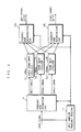
- FIG. 1 is a block diagram showing the structure of a sound image localization apparatus according to a first embodiment of the present invention.
- the sound image localization apparatus according to the first embodiment includes an input sampling frequency detector 11, a basic sound image localizer 12, sound image localizers 13a and 13b, a frequency band decomposing part 14, and frequency band reconstructing parts 15a and 15b.
- the input sampling frequency detector 11 detects a sampling frequency of an input signal, and then notifies the frequency band decomposing part 14 and the frequency band reconstructing parts 15a and 15b of the detection result. For example, when the input signal is a bit stream composed of a sound signal and sampling frequency information, the sampling frequency can be detected by extracting the sampling frequency information.
- the basic sound image localizer 12 operates at a sampling frequency (hereinafter, basic frequency f S ) equal to the minimum input sampling frequency (48kHz) of the input signal.
- the basic sound image localizer 12 processes a signal of a frequency in a range of 0 to a Nyquist frequency of the basic frequency f S .
- the basic sound image localizer 12 is constructed in a circuit typically as shown in FIG. 14. Each filer coefficient therein is adjusted so as to be able to process a signal in a frequency band (hereinafter abbreviated as band signal) between 0 and the Nyquist frequency of the basic frequency f S , that is, [0kHz to 24kHz], for sound image localization.
- band signal a frequency band
- the sound image localizer 13a operates at a sampling frequency f S2 equal to the frequency of 96kHz which is next larger than the basic frequency f S of the input signal.
- the sound image localizer 13a processes a signal of a frequency in a range of a Nyquist frequency of the basic frequency f S to a Nyquist frequency of the sampling frequency f S2 .
- the sound image localizer 13a is also constructed in the circuit typically as shown in FIG. 14. Each filer coefficient therein is adjusted so as to be able to process a band signal between the Nyquist frequency of the basic frequency f S and that of the sampling frequency f S2 , that is, [24kHz to 48kHz], for sound image localization.
- the sound image localizer 13b operates at a sampling frequency f S3 equal to the frequency which is next larger than the sampling frequency f S2 , in this case, the maximum input sampling frequency (192kHz), of the input signal.
- the sound image localizer 13b processes a signal of a frequency in a range of the Nyquist frequency of the sampling frequency f S2 to that of the sampling frequency f S3 .
- the sound image localizer 13b is also constructed in the circuit typically as shown in FIG. 14. Each filer coefficient therein is adjusted so as to be able to process a band signal between the Nyquist frequency of the sampling frequency f S2 and that of the sampling frequency f S3 , that is, [48kHz to 96kHz], for sound image localization.
- the frequency band decomposing part 14 decomposes the input signal into band signals of [0kHz to 24kHz], [24kHz to 48kHz], and [48kHz to 96kHz] according to the sampling frequency of the input signal detected by the input sampling frequency detector 11 and the Nyquist frequency of the sampling frequency.
- the sampling frequencies of these band signals are 48kHz, 96kHz, and 192kHz, respectively. Note that it is substantially impossible to perform ideal band decomposing without crossover. Therefore, practically, as shown in FIG. 2, each band signal has some crossovers with its adjacent band signals.
- the frequency band reconstructing part 15a reconstructs left channel signals outputted from the basic sound image localizer 12 and the sound image localizers 13a and 13b, and produces a left channel signal output at a sampling frequency equal to that of the input signal.
- the frequency band reconstructing part 15b reconstructs right channel signals outputted from the basic sound image localizer 12 and the sound image localizers 13a and 13b, and produces a right channel signal output at a sampling frequency equal to that of the input signal.
- the operation carried out by the sound image localization apparatus according to the first embodiment is now described in detail.
- the operation varies depending on the sampling frequency of the input signal, as described below.
- the input sampling frequency detector 11 detects the sampling frequency of the input signal as 48kHz. Then, based on the detection result from the input sampling frequency detector 11, the frequency band decomposing part 14 outputs the input signal as it is without decomposing to the basic sound image localizer 12. This is because the input signal is, as it is, a band signal of [0kHz to 24kHz].
- the signal outputted from the frequency band decomposing part 14 is processed in the basic sound image localizer 12 for sound image localization, provided as left and right channel signals to the frequency band reconstructing parts 15a and 15b, and outputted as they are as sound signals of the sampling frequency of 48kHz. Note that when the sampling frequency of the input signal is 48kHz, the sound image localizers 13a and 13b do not have to carry out the sound image localization process.
- the input sampling frequency detector 11 detects the sampling frequency of the input signal as 96kHz. Then, based on the detection result from the input sampling frequency detector 11, the frequency band decomposing part 14 decomposes the input signal into two band signals of [0kHz to 24kHz] and [24kHz to 48kHz].
- the band signal of [0kHz to 24kHz] is subjected to down-sampling (band-limitation and decimation by a low-pass filer), thereby down in sampling frequency to 48kHz. This down-sampling enables the basic sound image localizer 12 to process the band signal of [0kHz to 24kHz] for sound image localization.
- the band signal of [0kHz to 24kHz] outputted from the frequency band decomposing part 14 is processed by the basic sound image localizer 12 for sound image localization.
- the band signal of [24kHz to 48kHz] outputted from the frequency band decomposing part 14 is provided as it is at the sampling frequency 96kHz to the sound image localizer 13a for the sound image localization process.
- the processed band signals are provided as left and right channel signals to the frequency band reconstructing parts 15a and 15b, respectively.
- the band signal processed for sound image localization by the basic sound image localizer 12 is subjected to up-sampling, thereby being back to the signal of the sampling frequency of 96kHz.
- this band signal is reconstructed with the band signal processed by the sound image localizer 13a, and produced as a sound signal of the sampling frequency of 96kHz. Note that when the sampling frequency of the input signal is 96kHz, the sound image localizer 13b does not have to carry out the sound image localization process.
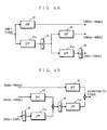
- FIG. 3A One example of a 2-band decomposing circuit is shown in FIG. 3A, while one example of a 2-band reconstructing circuit is shown in FIG. 3B.
- the 2-band decomposing circuit includes an LPF 31a, an HPF 32, and a down-sampler 34.
- the 2-band reconstructing circuit includes an LPF 31b, an APF 33, and an up-sampler 35.
- the LPFs 31a and 31b, the HPF 32, and the APF 33 are digital filters.
- the LPFs 31a and 31b each have a predetermined low-pass characteristic.
- LPFs 31a and 31b are provided to prevent occurrence of aliasing signals due to decimation.
- the HPF 32 has a high-pass characteristic.
- the APF 33 has an all-pass characteristic.
- the down-sampler 34 down-samples the sampling frequency to half.
- the up-sampler 35 up-samples the sampling frequency to be doubled.
- the input sampling frequency detector 11 detects the sampling frequency of the input signal as 192kHz. Then, based on the detection result from the input sampling frequency detector 11, the frequency band decomposing part 14 decomposes the input signal into three band signals of [0kHz to 24kHz], [24kHz to 48kHz], and [48kHz to 96kHz].
- the band signals of [0kHz to 24kHz] and [24kHz to 48kHz] are subject to down-sampling, thereby down in sampling frequency to 48kHz and 96kHz, respectively.
- the band signal of [0kHz to 24kHz] outputted from the frequency band decomposing part 14 is processed by the basic sound image localizer 12 for sound image localization.
- the band signal of [24kHz to 48kHz] outputted from the frequency band decomposing part 14 is provided to the sound image localizer 13a for the sound image localization process.
- the band signal of [48kHz to 96kHz] outputted from the frequency band decomposing part 14 is provided as it is at the sampling frequency 192kHz to the sound image localizer 13b for the sound image localization process.
- the processed band signals are provided as left and right channel signals to the frequency band reconstructing parts 15a and 15b, respectively.
- the band signals processed for sound image localization by the basic sound image localizer 12 and the sound image localizer 13a are subjected to up-sampling, thereby being back to the sampling frequency 192kHz. Then, the band signals are reconstructed with the band signal processed by the sound image localizer 13b, and produced as a sound signal of the sampling frequency of 192kHz.
- Circuits capable of decomposing and reconstructing for the signal of three frequency bands can also be realized by various circuits.
- the structure of the 2-band decomposing circuit shown in FIG. 3A is connectively provided again subsequent to the LPF to achieve a 3-band decomposing circuit.
- the structure of the 2-band reconstructing circuit shown in FIG. 3B is connectively provided again subsequent to the LPF to achieve a 3-band reconstructing circuit.
- decomposed band signals of [0kHz to 24kHz], [24kHz to 48kHz], [48kHz to 96kHz] are processed individually.
- the circuits for the sound image localizers 13a and 13b can be made small in structure.
- the effects of the present invention are considered as to the number of required filter coefficients and the operation power, compared with the method using the conventional art.
- the order of filters used in the basic sound image localizer 12 is taken as reference.
- the sampling frequency of the sound image localizer 13a is twice as that of the basic sound image localizer 12.
- the frequency band for process is [24kHz to 48kHz], and therefore the bandwidth thereof is equal to that in the basic sound image localizer 12.
- the order of filters in the sound localizer 13a can be thought approximately equal to that in the basic sound image lccalizer 12.
- the sampling frequency of the sound image localizer 13b is four times as that of the basic sound image localizer 12.
- the frequency band for process is [48kHz to 96kHz] , and therefore the bandwidth thereof is twice as that in the basic sound image localizer 12.
- the sound image localization apparatus of the present invention requires the structure of the frequency band decomposing part 14 and the frequency band reconstructing parts 15a and 15b, which is not required in the conventional apparatus, and thereby becomes large in structure.
- this structure can be implemented by a relatively small circuit, compared with the basic sound image localizer 12 and the sound image localizers 13a and 13b. Therefore, the effects of the present invention are not impaired.
- the frequency band for process by the sound image localizer 13b is between the Nyquist frequency of the sampling frequency f S2 and that of the sampling frequency f S3 , that is, [48kHz to 96kHz].
- This frequency band can be set between the Nyquist frequency of the basic frequency f s and that of the sampling frequency f S3 , that is, [24kHz to 96 kHz] .
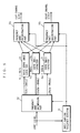
- the structure of the sound image localization apparatus becomes as shown in FIG. 5.
- the frequency band for process by the basic sound image localizer 12 is set to [0kHz to 24kHz], and that by sound image localizers 13a and 51 are [24kHz to 48kHz] and [24kHz to 96kHz], respectively.
- a frequency band decomposing part 52 decomposes the input signal into band signals of [0kHz to 24kHz], [24kHz to 48kHz], and [24kHz to 96kHz], based on the sampling frequency detected by the input sampling frequency detector 11.
- the frequency band reconstructing parts 15a and 15b each reconstruct the processed band signals, and produce a signal at a sampling frequency equal to that of the input signal. With this process band setting, only the basic sound image localizer 12 and any one of the sound image localizers will do for sound image localization.
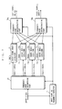
- the sound image localization apparatus can be more simplified in structure by the sound image localizers 13a and 13b carrying out only simple filtering (small in order) or carrying out delay processing and sound volume adjusting as shown in FIG. 6.
- the reasons are as follows:
- the resolution of human hearing is logarithmically decreased as the frequency becomes higher.
- High-frequency signals (more than 10kHz, for example) are less involved in sound image localization, and sounds of frequencies over 20kHz are generally not audible.
- the wavelength becomes shorter, and therefore, even a small difference between hearing positions may make it difficult to carry out sound image localization at higher frequency.
- the basic frequency f S is equal to the minimum input sampling frequency.
- a divisor of the minimum input sampling frequency may be used for the basic frequency f S for sound image localization. For example, if the minimum input sampling frequency is 48kHz, its divisor such as 24kHz or 12kHz can be used. With reference to FIG. 7, a case where the basic frequency f S is 24kHz is now described below.
- the basic frequency f S is 24kHz, which is half the minimum input sampling frequency 48kHz. Therefore, a basic sound image localizer 71 covers [0kHz to 12kHz]. Sound image localizers 72a, 72b, and 72c cover [12kHz to 24kHz], [12kHz to 48kHz], and [12kHz to 96kHz] , respectively.
- the basic sound image localizer 71 and the sound image localizer 72a process the input signal for sound image localization when the sampling frequency is 48kHz; the basic sound image localizer 71 and the sound image localizer 72b do when 96kHz; and the basic sound image localizer 71 and the sound image localizer 72c do when 192kHz.
- a frequency band decomposing part 73 decomposes the input signal into band signals of [0kHz to 12kHz], [12kHz to 24kHz], [12kHz to 48kHz], and [12kHz to 96kHz], according to the sampling frequency detected by the input sampling frequency detector 11.
- Frequency band reconstructing parts 74a and 74b each reconstruct the band signals after sound image localization, and then produce a signal at a sampling signal equal to that of the input signal.
- each band for process and the number of sound image localizers are appropriately determined so as to enable sound image localization for each sampling frequency.
- the sampling frequency of the input signal can take values of 48kHz, 96kHz, and 192kHz. Also in a case where the sampling frequency can take other frequency values (for example, 44.1kHz, 88.2kHz, and 176. 4kHz), sound image localization can be similarly achieved by a structure using basic sound image localizer and one or more sound image localizers for each sampling frequency.
- the circuits of the basic sound image localizer and sound image localizers may vary in structure depending on whether 2-front-speakers or headphones. If the present invention is applied to headphones, headphone-dedicated sound image localization circuits have to be used.
- headphone-dedicated sound image localization circuit is disclosed in Japanese Patent Laid-Open Publication No. 8-182100 (1996-182100).
- the sound image localization apparatus for carrying out sound image localization process on a 1-channel input signal is described.
- a sound image localization apparatus for carrying out the process on multi-channel input signals is described.
- a sound image localization apparatus for carrying out the process on 2-channel input signals is exemplarily described.
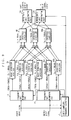
- FIG. 8 is a block diagram showing the structure of the sound image localization apparatus according to a second embodiment of the present invention.
- the sound image localization apparatus according to the second embodiment includes the input sampling frequency detector 11, two basic sound image localizers 12, two sound image localizers 13a and 13b, two frequency band decomposing parts 14, and six adders 16a to 16f, and the frequency band reconstructing parts 15a and 15b.
- the sound image localization apparatus according to the second embodiment are provided with two sets of the frequency band decomposing part 14, the basic sound image localizer 12, and the sound image localizers 13a and 13b.
- the sound image localization process described in the first embodiment is performed on each of first and second input signals.
- the resultant signals are added up for each frequency band by the adders 16a to 16f, and then provided to the frequency band reconstructing parts 15a and 15b.
- the frequency band reconstructing parts 15a and 15b each produce a sound signal at a sampling frequency equal to that of the input signal.
- the frequency band reconstructing parts 15a and 15b can be shared irrespectively of the number of channels. Therefore, the circuits can be reduced in size. Note that, in sound image localization for input signals of three or more channels, the set of the basic sound image localizer 12 and the sound image localizers 13a and 13b are provided as many as the number of channels.
- a sound image localization apparatus shown in FIG. 9 has a structure in which a basic direction localizer 91 and a basic crosstalk canceller 93 replace the basic sound image localizer 12; a direction localizer 92a and a crosstalk canceller 94a replace the sound image localizer 13a; and a direction localizer 92b and a crosstalk canceller 94b replace the sound image localizer 13b.
- output signals from the basic direction localizer 91 and the direction localizers 92a and 92b are added up for each frequency band by the adders 16a to 16f, and then subjected to crosstalk canceling. Therefore, in the sound image localization apparatus, the basic crosstalk canceller 93 and the crosstalk cancellers 94a and 94b can be shared for each frequency band Also, the circuits can be further reduced in size.
- crosstalk canceling will not go well because as the frequency becomes higher, the phase shift due to displacement of a listening position from the sound image becomes wider.
- the crosstalk cancellers 94a and 94b may be omitted. At this time, only the channel signals in a direction of a localized sound image may be outputted from the direction localizers 92a and 92b.
- FIG. 10 A circuit in a case where the present invention is applied to 5-channel digital sound signals used for DVD-Video, DVD-Audio, and others is shown in FIG. 10.
- Five channels correspond to, as shown in FIG. 11, front-left L, front-right R, center-front C, rear-left SL, and rear-right SR.
- Normally, five speakers are placed corresponding to the five channels for sound image localization.
- two speakers arranged at L and R channel positions are used for sound image localization for five channels.
- a 2-channel input sound image localizer 101 (FIG. 8 or 9) that can process 2-channel input signals as described above is used for sound image localization.
- a delay circuit may be provided before the signals are added in order to delay inputs for a time delayed in the 2-channel input sound image localizer 101, thereby reducing output time differences among all channels.
- the sound image localization apparatuses for localizing a sound image when the input signal is a general sound signal (for example, multi-bit PCM bit stream).
- a sound image localization apparatus that can support not only a multi-bit PCM bit stream but also a bit stream obtained by ⁇ ⁇ modulating a sound signal by each bit (hereinafter, ⁇ ⁇ modulated bit stream) used in a super audio CD (described in Super Audio CD System Description).
- FIG. 12 is a block diagram showing the structure of the sound image localization apparatus according to the third embodiment of the present invention.
- the sound image localization apparatus according to the third embodiment includes an input format discriminator 122, a switch 123, a decimator 124, and a sound image localizer 121.
- the input format discriminator 122 discriminates, as to the input signal, between a ⁇ ⁇ modulated bit stream or a multi-bit PCM bit stream.
- the decimator 124 down-samples the input signal to a sampling frequency supported by the sound image localizer 121.
- the switch 123 selectively switches between the input signal as it is or down-sampled input signal based on the discrimination result by the input format discriminator 122.
- the switch 123 outputs the selected signal to the sound image localizer 121.
- the sound image localizer 121 is equivalent to the sound image localization apparatus according to the first embodiment. Based on the discrimination result by the input format discriminator 122, the sound image localizer 121 subjects the signal outputted from the switch 123 to the sound image localization process.
- the input format discriminator 122 discriminates, as to the input signal, between a ⁇ ⁇ modulated bit stream or a multi-bit PCM bit stream.
- the discrimination result is given to the switch 123 and the sound image localizer 121.
- the operation thereafter varies based on the discrimination result.
- the input signal is a multi-bit PCM bit stream.
- the switch 123 connects a terminal A and a terminal C together, outputting the input signal as it is to the sound image localizer 121.
- the sound image localizer 121 subjects the received input signal to the sound image localization process similar to that in the first embodiment.
- the decimator 124 does not have to operate.
- the decimator 124 eliminates an aliasing signal (unnecessary component) from the input signal. Then, the decimator 124 down-samples the resultant signal to a multi-bit PCM bit stream at a sampling frequency of 176.4kHz that can be processed by the sound image localizer 121.
- the switch 123 connects a terminal B and the terminal C together, outputting the down-sampled input signal to the sound image localizer 121.
- the sound image localizer 121 subjects the received signal to sound image localization process similar to that of the first embodiment.
- the input sampling frequency detector 11 of the sound image localizer 121 is given information from the input format discriminator 122 that the sampling frequency of the input signal is 176.4kHz. Therefore, the sound image localizer 121 outputs a sound signal at a sampling frequency 176.4kHz.
- sound image localization can be performed also on the ⁇ ⁇ modulated bit stream.
- the input signal is a 1-channel signal.
- a sound image localization apparatus supporting multi-channel input signals as shown in the second embodiment and providing a plurality of decimators 124 and switches 123, multi-channel input signals can also be processed.
Landscapes
- Physics & Mathematics (AREA)
- Engineering & Computer Science (AREA)
- Acoustics & Sound (AREA)
- Signal Processing (AREA)
- Stereophonic System (AREA)
- Electrophonic Musical Instruments (AREA)
Abstract
Description
FL = TL/HLL FR = TR/HRR
the plurality of sound image localizers may operate at the sampling frequency fk (k = 1 to n), and carry out sound image localization on a signal within a frequency band between a Nyquist frequency of the sampling frequency f0 and a Nyquist frequency of the sampling frequency fk.
- a plurality of adders for adding signals outputted from the basic direction localizers and the plurality of direction localizers for each frequency band and each output channel,
- a basic crosstalk canceller for carrying out crosstalk cancellation on the added signals outputted from the basic direction localizers; and
- a plurality of crosstalk cancellers for carrying out crosstalk cancellation on the added signals outputted from the plurality of direction localizers, and
- a plurality of frequency band reconstructing parts for reconstructing, based on the detection result of the input sampling frequency detector, signals outputted from the basic crosstalk canceller and the plurality of crosstalk cancellers for each output channel.
Claims (12)
- A sound image localization apparatus provided with a sound signal of n (n is an integer not less than 2) sampling frequencies f1 to fn (each frequency satisfies fm-1 < fm (m = 2 to n) and fm is a multiple of f1) for carrying out sound image localization, said apparatus comprising:an input sampling frequency detector (11) for detecting the sampling frequency of said sound signal;a basic sound image localizer (12) that operates at said sampling frequency f1 and carries out sound image localization on a signal within a frequency band that is lower than a Nyquist frequency of the sampling frequency f1;a plurality of sound image localizers (13a, 13b) that operate at said sampling frequency fm and carry out sound image localization on a signal within a frequency band between a Nyquist frequency of said sampling frequency fm-1 and a Nyquist frequency of the sampling frequency fm;a frequency band decomposing part (14) for decomposing, based on a detection result of said input sampling frequency detector (11), said sound signal into signals of the frequency bands covered by said basic sound image localizer (12) and said plurality of sound image localizers (13a, 13b); anda plurality of frequency band reconstructing parts (15a, 15b) for reconstructing, based on the detection result of said input sampling frequency detector (11), the signals outputted from said basic sound image localizer (12) and said plurality of sound image localizers (13a, 13b) for each output channel.
- A sound image localization apparatus provided with a sound signal of n (n is an integer not less than 2) sampling frequencies f1 to fn (each frequency satisfies fm-1 < fm (m = 2 to n) and fm is a multiple of f1) for carrying out sound image localization, said apparatus comprising:an input sampling frequency detector (11) for detecting the sampling frequency of said sound signal;a basic sound image localizer (12) that operates at said sampling frequency f1 and carries out sound image localization on a signal within a frequency band that is lower than a Nyquist frequency of the sampling frequency f1;a plurality of sound image localizers (13a, 51) that operate at said sampling frequency fm and carry out sound image localization on a signal within a frequency band between a Nyquist frequency of said sampling frequency f1 and a Nyquist frequency of the sampling frequency fm;a frequency band decomposing part (52) for decomposing, based on a detection result of said input sampling frequency detector (11), said sound signal into signals of the frequency bands covered by said basic sound image localizer (12) and said plurality of Sound image localizers (13a, 51); anda plurality of frequency band reconstructing parts (15a, 15b) for reconstructing, based on the detection result of said input sampling frequency detector (11), the signals outputted from said basic sound image localizer (12) and said plurality of sound image localizers (13a, 51) for each output channel.
- A sound image localization apparatus provided with a sound signal of n (n is an integer not less than 2) sampling frequencies f1 to fn (each frequency satisfies fk-1 < fk (k = 1 to n)) for carrying out sound image localization, said apparatus comprising:an input sampling frequency detector (11) for detecting the sampling frequency of said sound signal;a basic sound image localizer (71) that operates at a sampling frequency f0, which is a divisor of said sampling frequency f1, and carries out sound image localization on a signal within a frequency band that is lower than a Nyquist frequency of the sampling frequency f0;a plurality of sound image localizers (72a-72c) that operate at said sampling frequency fk and carry out sound image localization on a signal within a frequency band between a Nyquist frequency of said sampling frequency f0 and a Nyquist frequency of the sampling frequency fk;a frequency band decomposing part (73) for decomposing, based on a detection result of said input sampling frequency detector (11), said sound signal into signals of the frequency bands covered by said basic sound image localizer (71) and said plurality of sound image localizers (72a-72c); anda plurality of frequency band reconstructing parts (74a, 74b) for reconstructing, based on the detection result of said input sampling frequency detector (11), the signals outputted from said basic sound image localizer (71) and said plurality of sound image localizers (72a-72c) for each output channel.
- A sound image localization apparatus provided with a plurality of sound signals of n (n is an integer not less than 2) sampling frequencies f1 to fn (each frequency satisfies fm-1 < fm (m = 2 to n) and fm is a multiple of f1) for carrying out sound image localization on each of said sound signals, said apparatus comprising:an input sampling frequency detector (11) for detecting the sampling frequency of said sound signal;for each of said plurality of sound signals,a basic sound image localizer (12) that operates at said sampling frequency f1 and carries out sound image localization on a signal within a frequency band that is lower than a Nyquist frequency of the sampling frequency f1;a plurality of sound image localizers (13a, 13b) that operate at said sampling frequency fm and carry out sound image localization on a signal within a frequency band between a Nyquist frequency of said sampling frequency fm-1 and a Nyquist frequency of the sampling frequency fm; anda frequency band decomposing part (14) for decomposing, based on a detection result of said input sampling frequency detector (11) , said sound signal into signals of the frequency bands covered by said basic sound image localizer (12) and said plurality of sound image localizers(13a, 13b),a plurality of adders for adding signals outputted from said basic sound image localizers (12) and said plurality of sound image localizers (13a, 13b) together for each frequency band and each output channel; anda plurality of frequency band reconstructing parts (15a, 15b) for reconstructing, based on the detection result of said input sampling frequency detector (11), signals outputted from said plurality of adders for each output channel.
- A sound image localization apparatus provided with a plurality of sound signals of n (n is an integer not less than 2) sampling frequencies f1 to fn (each frequency satisfies fm-1 < fm (m = 2 to n) and fm is a multiple of f1) for carrying out sound image localization on each of said sound signals, said apparatus comprising:an input sampling frequency detector (11) for detecting the sampling frequency of said sound signal;for each of said plurality of sound signals,a basic direction localizer (91) that operates at said sampling frequency f1 and carries out direction localization on a signal within a frequency band that is lower than a Nyquist frequency of the sampling frequency f1;a plurality of direction localizers (92a, 92b) that operate at said sampling frequency fm and carry out direction localization on a signal within a frequency band between a Nyquist frequency of said sampling frequency fm-1 and a Nyquist frequency of the sampling frequency fm; anda frequency band decomposing part (14) for decomposing, based on a detection result of said input sampling frequency detector (11), said sound signal into signals of the frequency bands covered by said basic direction localizer (91) and said plurality of direction localizers (92a, 92b),a plurality of adders for adding signals outputted from said basic direction localizers (91) and said plurality of direction localizers (92a, 92b) for each frequency band and each output channel,a basic crosstalk canceller (93) for carrying out crosstalk cancellation on the added signals outputted from said basic direction localizers (91); anda plurality of frequency band reconstructing parts (15a, 15b) for reconstructing, based on the detection result of said input sampling frequency detector (11), signals outputted from any of said plurality of adders that are dedicated to said plurality of direction localizers (92a, 92b) and the signal outputted from said basic crosstalk canceller (93) for each output channel.
- A sound image localization apparatus provided with a plurality of sound signals of n (n is an integer not less than 2) sampling frequencies f1 to fn (each frequency satisfies fm-1 < fm (m = 2 to n) and fm is a multiple of f1) for carrying out sound image localization on each of said sound signals, said apparatus comprising:an input sampling frequency detector (11) for detecting the sampling frequency of said sound signal;for each of said plurality of sound signals,a basic direction localizer (91) that operates at said sampling frequency f1 and carries out direction localization on a signal within a frequency band that is lower than a Nyquist frequency of the sampling frequency f1;a plurality of direction localizers (92a, 92b) that operate at said sampling frequency fm and carry out direction localization on a signal within a frequency band between a Nyquist frequency of said sampling frequency fm-1 and a Nyquist frequency of the sampling frequency fm; anda frequency band decomposing part (14) for decomposing, based on a detection result of said input sampling frequency detector (11), said sound signal into signals of the frequency bands covered by said basic direction localizer (91) and said plurality of direction localizers (92a, 92b),a plurality of adders adding signals outputted from said basic direction localizers (91) and said plurality of direction localizers (92a, 92b) for each frequency band and each output channel,a basic crosstalk canceller (93) for carrying out crosstalk cancellation on the added signals outputted from said basic direction localizers (91);a plurality of crosstalk cancellers (94a, 94b) for carrying out crosstalk cancellation on the added signals outputted from said plurality of direction localizers (92a, 92b); anda plurality of frequency band reconstructing parts (15a, 15b) for reconstructing, based on the detection result of said input sampling frequency detector (11), signals outputted from said basic crosstalk canceller (93) and said plurality of crosstalk cancellers (94a, 94b) for each output channel.
- The sound image localization apparatus according to claim 1, further comprising:an input format discriminator (122) for discriminating, as to said sound signal, between a bit stream Σ Δ modulated by each bit and a multi-bit PCM bit stream,a decimator (124) for down-sampling said sound signal; anda switching part (123) for switching, for output to said frequency band decomposing part (14) , to a signal outputted from said decimator (124) when said input format discriminator (122) discriminates said sound signal as the bit stream Σ Δ modulated by each bit, and to said sound signal as it is when said input format discriminator (122) discriminates said sound signal as the multi-bit PCM bit stream.
- The sound image localization apparatus according to claim 2, further comprising:an input format discriminator (122) for discriminating, as to said sound signal, between a bit stream Σ Δ modulated by each bit and a multi-bit PCM bit stream,a decimator (124) for down-sampling said sound signal; anda switching part (123) for switching, for output to said frequency band decomposing part (14), to a signal outputted from said decimator (124) when said input format discriminator (122) discriminates said sound signal as the bit stream Σ Δ modulated by each bit, and to said sound signal as it is when said input format discriminator (122) discriminates said sound signal as the multi-bit PCM bit stream.
- The sound image localization apparatus according to claim 3, further comprising:an input format discriminator (122) for discriminating, as to said sound signal, between a bit stream Σ Δ modulated by each bit and a multi-bit PCM bit stream,a decimator (124) for down-sampling said sound signal; anda switching part (123) for switching, for output to said frequency band decomposing part (14), to a signal outputted from said decimator (124) when said input format discriminator (122) discriminates said sound signal as the bit stream Σ Δ modulated by each bit, and to said sound signal as it is when said input format discriminator (122) discriminates said sound signal as the multi-bit PCM bit stream.
- The sound image localization apparatus according to claim 4, further comprising:
for each of said sound signals,an input format discriminator (122) for discriminating, as to said sound signal, between a bit stream Σ Δ modulated by each bit and a multi-bit PCM bit stream,a decimator (124) for down-sampling said sound signal; anda switching part (123) for switching, for output to said frequency band decomposing part (14), to a signal outputted from said decimator (124) when said input format discriminator (122) discriminates said sound signal as the bit stream Σ ▵ modulated by each bit, and to said sound signal as it is when said input format discriminator (122) discriminates said sound signal as the multi-bit PCM bit stream. - The sound image localization apparatus according to claim 5, further comprising:
for each of said sound signals,an input format discriminator (122) for discriminating, as to said sound signal, between a bit stream Σ ▵ modulated by each bit and a multi-bit PCM bit stream,a decimator (124) for down-sampling said sound signal; anda switching part (123) for switching, for output to said frequency band decomposing part (14), to a signal outputted from said decimator (124) when said input format discriminator (122) discriminates said sound signal as the bit stream Σ Δ modulated by each bit, and to said sound signal as it is when said input format discriminator (122) discriminates said sound signal as the multi-bit PCM bit stream. - The sound image localization apparatus according to claim 6, further comprising:
for each of said sound signals,an input format discriminator (122) for discriminating, as to said sound signal, between a bit stream Σ Δ modulated by each bit and a multi-bit PCM bit stream,a decimator (124) for down-sampling said sound signal; anda switching part (123) for switching, for output to said frequency band decomposing part (14) , to a signal outputted from said decimator (124) when said input format discriminator (122) discriminates said sound signal as the bit stream Σ Δ modulated by each bit, and to said sound signal as it is when said input format discriminator (122) discriminates said sound signal as the multi-bit PCM bit stream.
Applications Claiming Priority (2)
| Application Number | Priority Date | Filing Date | Title |
|---|---|---|---|
| JP36717499 | 1999-12-24 | ||
| JP36717499A JP2001186600A (en) | 1999-12-24 | 1999-12-24 | Sound image localization device |
Publications (2)
| Publication Number | Publication Date |
|---|---|
| EP1111961A2 true EP1111961A2 (en) | 2001-06-27 |
| EP1111961A3 EP1111961A3 (en) | 2004-02-11 |
Family
ID=18488658
Family Applications (1)
| Application Number | Title | Priority Date | Filing Date |
|---|---|---|---|
| EP00127950A Withdrawn EP1111961A3 (en) | 1999-12-24 | 2000-12-21 | Sound image localization apparatus |
Country Status (5)
| Country | Link |
|---|---|
| US (1) | US20010005824A1 (en) |
| EP (1) | EP1111961A3 (en) |
| JP (1) | JP2001186600A (en) |
| KR (1) | KR20010062616A (en) |
| CN (1) | CN1302172A (en) |
Families Citing this family (9)
| Publication number | Priority date | Publication date | Assignee | Title |
|---|---|---|---|---|
| US6404779B1 (en) * | 1997-10-08 | 2002-06-11 | Bandwidth Technology Corp. | System and method of disharmonic frequency multiplexing |
| JP4580689B2 (en) | 2004-05-31 | 2010-11-17 | ソニー株式会社 | Sound image localization apparatus, sound image localization method, and sound image localization program |
| US20070165890A1 (en) * | 2004-07-16 | 2007-07-19 | Matsushita Electric Industrial Co., Ltd. | Sound image localization device |
| EP1860917A1 (en) * | 2005-03-10 | 2007-11-28 | Mitsubishi Electric Corporation | Sound image localization apparatus |
| KR100619082B1 (en) | 2005-07-20 | 2006-09-05 | 삼성전자주식회사 | Wide mono sound playback method and system |
| JP2007057584A (en) * | 2005-08-22 | 2007-03-08 | Kenwood Corp | Audio apparatus and sound effect setting method |
| JP5533248B2 (en) * | 2010-05-20 | 2014-06-25 | ソニー株式会社 | Audio signal processing apparatus and audio signal processing method |
| CN111406414B (en) * | 2017-12-01 | 2022-10-04 | 株式会社索思未来 | Signal processing device and signal processing method |
| CN113138367B (en) * | 2020-01-20 | 2024-07-26 | 中国科学院上海微系统与信息技术研究所 | Target positioning method and device, electronic equipment and storage medium |
Family Cites Families (4)
| Publication number | Priority date | Publication date | Assignee | Title |
|---|---|---|---|---|
| EP0666556B1 (en) * | 1994-02-04 | 2005-02-02 | Matsushita Electric Industrial Co., Ltd. | Sound field controller and control method |
| WO1995034883A1 (en) * | 1994-06-15 | 1995-12-21 | Sony Corporation | Signal processor and sound reproducing device |
| TW379512B (en) * | 1997-06-30 | 2000-01-11 | Matsushita Electric Industrial Co Ltd | Apparatus for localization of a sound image |
| US6175631B1 (en) * | 1999-07-09 | 2001-01-16 | Stephen A. Davis | Method and apparatus for decorrelating audio signals |
-
1999
- 1999-12-24 JP JP36717499A patent/JP2001186600A/en active Pending
-
2000
- 2000-12-19 US US09/739,380 patent/US20010005824A1/en not_active Abandoned
- 2000-12-21 EP EP00127950A patent/EP1111961A3/en not_active Withdrawn
- 2000-12-22 KR KR1020000080161A patent/KR20010062616A/en not_active Withdrawn
- 2000-12-25 CN CN00137067A patent/CN1302172A/en active Pending
Also Published As
| Publication number | Publication date |
|---|---|
| CN1302172A (en) | 2001-07-04 |
| EP1111961A3 (en) | 2004-02-11 |
| JP2001186600A (en) | 2001-07-06 |
| US20010005824A1 (en) | 2001-06-28 |
| KR20010062616A (en) | 2001-07-07 |
Similar Documents
| Publication | Publication Date | Title |
|---|---|---|
| JP4732807B2 (en) | Audio signal processing | |
| US8442241B2 (en) | Audio signal processing for separating multiple source signals from at least one source signal | |
| US7177431B2 (en) | Dynamic decorrelator for audio signals | |
| CN100493235C (en) | Shafura type audio signal processing circuit and method | |
| AU2006268773B2 (en) | A system and method for eliminating feedback and noise in a hearing device | |
| US5638452A (en) | Expandable multi-dimensional sound circuit | |
| EP1746863A2 (en) | Method and apparatus to reproduce wide mono sound | |
| CA2543614A1 (en) | Multi-channel audio surround sound from front located loudspeakers | |
| EP1283658A2 (en) | Multi channel audio reproduction system | |
| EP1111961A2 (en) | Sound image localization apparatus | |
| US8064607B2 (en) | Method for producing more than two electric time signals from one first and one second electric time signal | |
| JP3513850B2 (en) | Sound image localization processing apparatus and method | |
| US6052470A (en) | System for processing audio surround signal | |
| KR101637407B1 (en) | Apparatus and method and computer program for generating a stereo output signal for providing additional output channels | |
| JPH1094098A (en) | Method and device for generating multi-channel signal from monphonic signal | |
| US8107632B2 (en) | Digital signal processing apparatus, method thereof and headphone apparatus | |
| EP1054576A1 (en) | Pseudo-stereophony device | |
| US20080152152A1 (en) | Sound Image Localization Apparatus | |
| JPS6121636A (en) | Receiver reduced in interference of adjacent channel | |
| JP4594662B2 (en) | Sound image localization device | |
| JP3106788B2 (en) | In-vehicle sound field correction device | |
| WO2007035055A1 (en) | Apparatus and method of reproduction virtual sound of two channels | |
| EP0593850B1 (en) | Method and apparatus for subband filtering of a stereo audio signal | |
| JP3700254B2 (en) | Video / audio playback device | |
| JP2985704B2 (en) | Surround signal processing device |
Legal Events
| Date | Code | Title | Description |
|---|---|---|---|
| PUAI | Public reference made under article 153(3) epc to a published international application that has entered the european phase |
Free format text: ORIGINAL CODE: 0009012 |
|
| AK | Designated contracting states |
Kind code of ref document: A2 Designated state(s): AT BE CH CY DE DK ES FI FR GB GR IE IT LI LU MC NL PT SE TR |
|
| AX | Request for extension of the european patent |
Free format text: AL;LT;LV;MK;RO;SI |
|
| PUAL | Search report despatched |
Free format text: ORIGINAL CODE: 0009013 |
|
| AK | Designated contracting states |
Kind code of ref document: A3 Designated state(s): AT BE CH CY DE DK ES FI FR GB GR IE IT LI LU MC NL PT SE TR |
|
| AX | Request for extension of the european patent |
Extension state: AL LT LV MK RO SI |
|
| RIC1 | Information provided on ipc code assigned before grant |
Ipc: 7H 04S 1/00 B Ipc: 7H 04S 3/00 A |
|
| STAA | Information on the status of an ep patent application or granted ep patent |
Free format text: STATUS: THE APPLICATION HAS BEEN WITHDRAWN |
|
| 18W | Application withdrawn |
Effective date: 20040603 |