EP1111892A2 - Verfahren und Vorrichtungen zur Überwachung eines Internetprotokollnetzwerkes - Google Patents
Verfahren und Vorrichtungen zur Überwachung eines Internetprotokollnetzwerkes Download PDFInfo
- Publication number
- EP1111892A2 EP1111892A2 EP00311068A EP00311068A EP1111892A2 EP 1111892 A2 EP1111892 A2 EP 1111892A2 EP 00311068 A EP00311068 A EP 00311068A EP 00311068 A EP00311068 A EP 00311068A EP 1111892 A2 EP1111892 A2 EP 1111892A2
- Authority
- EP
- European Patent Office
- Prior art keywords
- end user
- media stream
- user device
- message
- identification information
- Prior art date
- Legal status (The legal status is an assumption and is not a legal conclusion. Google has not performed a legal analysis and makes no representation as to the accuracy of the status listed.)
- Granted
Links
- 238000000034 method Methods 0.000 title claims abstract description 65
- 230000011664 signaling Effects 0.000 claims abstract description 130
- 238000004891 communication Methods 0.000 claims description 58
- 230000004044 response Effects 0.000 claims description 24
- 238000004590 computer program Methods 0.000 claims description 13
- 230000000977 initiatory effect Effects 0.000 claims description 11
- 238000010586 diagram Methods 0.000 description 71
- 230000006870 function Effects 0.000 description 11
- 238000012544 monitoring process Methods 0.000 description 7
- 238000012545 processing Methods 0.000 description 6
- 238000013475 authorization Methods 0.000 description 2
- 239000003999 initiator Substances 0.000 description 2
- 230000003287 optical effect Effects 0.000 description 2
- 238000012546 transfer Methods 0.000 description 2
- 230000005540 biological transmission Effects 0.000 description 1
- 239000003795 chemical substances by application Substances 0.000 description 1
- 238000001514 detection method Methods 0.000 description 1
- 238000005516 engineering process Methods 0.000 description 1
- 238000010079 rubber tapping Methods 0.000 description 1
- 239000000523 sample Substances 0.000 description 1
- 230000009131 signaling function Effects 0.000 description 1
- 230000029305 taxis Effects 0.000 description 1
- 238000013519 translation Methods 0.000 description 1
Images


Classifications
-
- H—ELECTRICITY
- H04—ELECTRIC COMMUNICATION TECHNIQUE
- H04L—TRANSMISSION OF DIGITAL INFORMATION, e.g. TELEGRAPHIC COMMUNICATION
- H04L63/00—Network architectures or network communication protocols for network security
- H04L63/08—Network architectures or network communication protocols for network security for authentication of entities
-
- H—ELECTRICITY
- H04—ELECTRIC COMMUNICATION TECHNIQUE
- H04L—TRANSMISSION OF DIGITAL INFORMATION, e.g. TELEGRAPHIC COMMUNICATION
- H04L63/00—Network architectures or network communication protocols for network security
- H04L63/30—Network architectures or network communication protocols for network security for supporting lawful interception, monitoring or retaining of communications or communication related information
-
- H—ELECTRICITY
- H04—ELECTRIC COMMUNICATION TECHNIQUE
- H04L—TRANSMISSION OF DIGITAL INFORMATION, e.g. TELEGRAPHIC COMMUNICATION
- H04L65/00—Network arrangements, protocols or services for supporting real-time applications in data packet communication
- H04L65/10—Architectures or entities
- H04L65/102—Gateways
- H04L65/1043—Gateway controllers, e.g. media gateway control protocol [MGCP] controllers
-
- H—ELECTRICITY
- H04—ELECTRIC COMMUNICATION TECHNIQUE
- H04M—TELEPHONIC COMMUNICATION
- H04M3/00—Automatic or semi-automatic exchanges
- H04M3/22—Arrangements for supervision, monitoring or testing
- H04M3/2281—Call monitoring, e.g. for law enforcement purposes; Call tracing; Detection or prevention of malicious calls
-
- H—ELECTRICITY
- H04—ELECTRIC COMMUNICATION TECHNIQUE
- H04M—TELEPHONIC COMMUNICATION
- H04M7/00—Arrangements for interconnection between switching centres
- H04M7/006—Networks other than PSTN/ISDN providing telephone service, e.g. Voice over Internet Protocol (VoIP), including next generation networks with a packet-switched transport layer
-
- H—ELECTRICITY
- H04—ELECTRIC COMMUNICATION TECHNIQUE
- H04M—TELEPHONIC COMMUNICATION
- H04M7/00—Arrangements for interconnection between switching centres
- H04M7/12—Arrangements for interconnection between switching centres for working between exchanges having different types of switching equipment, e.g. power-driven and step by step or decimal and non-decimal
- H04M7/1205—Arrangements for interconnection between switching centres for working between exchanges having different types of switching equipment, e.g. power-driven and step by step or decimal and non-decimal where the types of switching equipement comprises PSTN/ISDN equipment and switching equipment of networks other than PSTN/ISDN, e.g. Internet Protocol networks
-
- H—ELECTRICITY
- H04—ELECTRIC COMMUNICATION TECHNIQUE
- H04M—TELEPHONIC COMMUNICATION
- H04M3/00—Automatic or semi-automatic exchanges
- H04M3/42—Systems providing special services or facilities to subscribers
- H04M3/42221—Conversation recording systems
Definitions
- the present invention relates generally to methods and systems for internet protocol (IP) network surveillance. More particularly, the present invention relates to methods and systems for performing surveillance of IP communications, such as voice telephone calls, data communications, audio communications, and video communications.
- IP internet protocol
- PSTN public switched telephone network
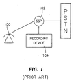
- telephone calls to and from the subject of a court-ordered wiretap can be recorded easily at the end office serving the subject.
- SSP service switching point
- all calls to or from end user device 100 pass through service switching point (SSP) 102 connected to end user device 100 .
- call signaling information used to set up and tear down a call involving end user device 100 passes through SSP 102 .
- the media stream i.e., the voice, data, video, or any combination thereof, passes through SSP 102 .
- a recording device 104 such as a magnetic tape recorder, is placed at SSP 102 to record call signaling and media stream information associated with end user device 100 .
- SSP 102 such as a magnetic tape recorder
- IP Internet protocol
- IP service providers providing IP services are classified as enhanced service providers rather than communications providers.
- Enhanced service providers are exempt from many taxes, tariffs, and other laws that affect communications service providers.
- Enhanced service providers such as America Online, have complied with FBI requests for user information relating to monitoring e-mail of a subscriber.
- a formal wire tapping capability for packet-based networks is likely to be imposed on IP service providers in the near future.
- One problem with collecting call signaling and media stream information in the IP domain is that the monitoring can be detectable by the end user.
- users In the PSTN network, users have very little or no access to the signaling for their calls.
- users In the IP domain, however, users can have full access to call signaling for their calls. Because the end users can have full access to the call signaling information, the end users might be able to detect surveillance. If the end users are able to detect surveillance, the surveillance becomes useless for law enforcement purposes.
- IP network surveillance Another possible solution to providing IP network surveillance is to use multicast, such as IP multicast, to send a copy of a call to a law enforcement agency. This solution is not practical because the end user's communication device will be able to determine that multicast is being used. Once the end user determines that multicast is being used, the end user will be alerted that he or she is under surveillance.
- multicast such as IP multicast
- IP surveillance is to use a conference bridge to allow a law enforcement agency to access the call.
- the user's communication device will be able to detect the presence of a conference bridge, e.g., using the Packet InterNet Groper (PING) or traceroute programs. Once the user detects the presence of the conference bridge, the user is alerted that he or she is under surveillance.
- PING Packet InterNet Groper
- the present invention includes methods and systems for performing IP network surveillance.
- an end user transmits call signaling information through a proxy server to establish a call with another end user.
- proxy and “proxy server”, are used interchangeably herein to refer to a computer program that functions as an intermediary between network entities.
- the proxy server communicates with an authentication server to authenticate the end user.
- the authentication server determines whether the end user is under surveillance. If the end user is under surveillance, the authentication server notifies the proxy server.
- the proxy server copies call signaling messages to or from the end user.
- the proxy server forwards copies of the signaling messages to a recording device.
- the proxy server determines media stream identification information for either or both end users.
- media stream refers to audio, voice, video, data, applications, or any combination thereof that is packetized and transmitted between end users in a network.
- the proxy server can also determine media stream decoding information for the end users.
- the proxy server transmits the media stream identification information and the media stream decoding information to a policy server.
- the policy server instructs an edge router to copy the media stream to or from the end user device based on the media stream identification information.
- the edge router copies the media stream to or from the end user device and sends a copy of the media stream to a recording device.
- the policy server can also transmit the media stream decoding information to the recording device to enable decoding of the media stream.
- Communications monitored may include audio communications, video communications, data communications, or any combination thereof. Accordingly, the terms “end user device”, “PSTN communication device”, and “IP communication device”, as used herein, include devices capable of communicating using one or more of the above-described media types.
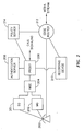
- FIG. 2 illustrates a communications network including a system for performing IP network surveillance according to an embodiment of the present invention.
- an end user device 200 can be an IP telephone capable of transmitting multimedia streams over a network, such as an IP network.
- end user device 200 is the subject of surveillance.
- a signaling gateway 201 and a media gateway 202 allow end user device 200 to communicate with other end user devices over a packet-based network.
- Either or both of the gateways 201 and 202 can implement a suitable control protocol, such as the Media Gateway Control Protocol (MGCP), that allows call signaling and control to be performed by an external entity, referred to as a call agent or media gateway controller.
- MGCP Media Gateway Control Protocol
- signaling gateway 201 and media gateway 202 are controlled by media gateway controller 204 .
- Media gateway controller 204 performs call signaling functions, such as communicating with the media gateway controller of another end user to establish a media communications between the end users. For example, media gateway controller 204 can formulate call setup and teardown messages to be communicated to the media gateway controller of another end user.
- Proxy 206 functions as an intermediary between entities of the network containing end user device 200 and other networks. Exemplary functions that can be performed by proxy 206 include address translation between internal and external network addresses, control of multimedia sessions, and firewall functions. An exemplary protocol that can be implemented by proxy server 206 to control multimedia sessions between end users is the Session Initiation Protocol (SIP). According to an important aspect of the invention, proxy 206 can also communicate with authentication server 208 to identify end users under surveillance.
- SIP Session Initiation Protocol
- Authentication server 208 performs user authentication and surveillance identification functions. For example, authentication server 208 can receive user identification information from end user device 200 and determine whether the user of end user device 200 is authorized to make calls. Such authentication can occur by performing a look up in a database to determine whether to allow communications to or from the end user. If authentication server 208 determines that the user is an authorized user, authentication server 208 communicates this fact to proxy server 206 . Proxy server 206 then allows communication with external network elements, such as the proxy server for another end user.
- authentication server 208 preferably includes a users-under-surveillance database.
- the users-under-surveillance database can be the same database or a different database from the database used to determine whether to allow users to communicate.
- the users-under-surveillance database can contain entries that correspond to users that are under surveillance.
- the keys for accessing the entries can include any end user identification information, such as the user's identification for logging onto the network, the IP address of the device through which the user accesses the IP network, or any other information useful for identifying an end user.
- the users-under-surveillance database is preferably programmable to allow a service provider or a law enforcement entity to add and delete users from the database and to modify user selection criteria. For example, it may be desirable to monitor IP telephone calls and not HTTP sessions for a given user.
- authentication server 208 When authentication server 208 receives an authentication message from proxy 206 , authentication server 208 can perform a look up in the users-under-surveillance database. If the authentication server 208 determines that the end user is under surveillance, authentication server 208 informs proxy 206 of this fact. In response to receiving notification that the end user is under surveillance, proxy 206 copies call signaling messages relating to calls to or from end user device 200 . Proxy 206 forwards copies of the call signaling messages to a recording device 210 . Recording device 210 can be an IP client that records call signaling messages received from proxy 206 in a log file.
- the media stream decoding information may be determined from call signaling messages or from the media packets themselves.
- the recording device 210 may decode the media stream in real time or store the media stream by controlling the edge router or edge routers that handle the media stream for an end user under surveillance.
- all media stream packets from an end user device are transmitted through one or more edge routers. There may be more than one edge router for purposes of load sharing. However, in such a case, surveillance may still be performed.
- Edge router 212 comprises a network entity that controls network access for any end user and is controlled by policy server 214 . Since all media stream packets to or from end user device 200 are guaranteed to pass through edge router 212 , this device can be used to copy the media stream associated with an end user under surveillance.
- proxy 206 When proxy 206 is notified that end user device 200 is the subject of surveillance, proxy 206 informs policy server 214 of this fact.
- a policy server is a network entity that instructs routers, such as edge router 212 , on how to control bandwidth and resources.
- An example of a policy server suitable for use as policy server 214 of the present invention is a DIFFSERV policy server.
- a DIFFSERV policy server includes multiple queues and a queue management program that implements differential quality of service for different calls.
- policy server 214 preferably also performs a surveillance function by instructing edge router 212 to copy the media stream for users under surveillance.
- policy server 214 can receive notification from proxy 206 that end user device 200 is the subject of surveillance.
- Policy server 214 can also receive media stream identification and decoding information from proxy 206 .
- Proxy 206 can also communicate media stream identification information and decoding information to policy server 206 .
- Policy server 214 can determine the edge router serving end user 200 from the media stream identification information and can communicate the media stream identification information and decoding information to edge router 212 .
- Edge router 212 can then forward copies of the media stream to and from end user device 200 to recording device 210 .
- Recording device 210 can store the media stream on a storage medium, such as a disk storage medium.
- Edge router 212 can also forward the media stream decoding information to recording device 210 to enable decoding of the media stream.
- proxy 206 , authentication server 208 , policy server 214 , and edge router 212 cooperate to perform IP network surveillance. Each of these components will now be discussed in more detail.
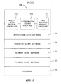
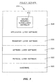
- FIG. 3 is a protocol layer diagram illustrating an exemplary architecture of a proxy server according to an embodiment of the present invention.
- proxy generally designated 206 includes hardware 300 for executing programs and for communicating with other entities over a network.
- proxy hardware can include one or more processors having associated program memory and data memory for storing programs and data, including programs and data for performing IP network surveillance according to embodiments of the present invention.
- Proxy hardware 300 can also include one or more communications adapters, such as one or more Ethernet adapters.
- An example of proxy server hardware suitable for use with the present invention is a general purpose computer, such as an IBM-compatible computer, a Macintosh computer, or a UNIX computer.
- Physical layer software 302 allows proxy 206 to communicate with devices directly connected to proxy 206 .
- Exemplary physical layer communications software includes media access control (MAC) software.
- Network layer software 304 includes functionality for communicating over a packet-based network, such as an IP network.
- Transport layer software includes functionality for reliable or unreliable communication with other devices.
- exemplary transport layer software suitable for use with the present invention includes transfer control protocol (TCP) or user datagram protocol (UDP) software.
- Application layer software 308 includes functionality for controlling access to internal and external networks, for performing authentication, for controlling multimedia sessions, and for performing IP network surveillance.
- application layer software 308 includes multimedia session controller 310 for controlling multimedia sessions between end users, authentication server interface 312 for communicating with authentication server 208 to determine whether an end user is under surveillance, and call signaling message processor 314 for copying call signaling messages and for determining media stream identification and decoding information from the call signaling messages.
- the present invention is not limited to proxy server 206 with an authentication server interface 312 for communicating with an authentication server to determine whether an end user is under surveillance.
- authentication server interface 312 may be replaced by a surveillance interface for communicating with any type of external entity, such as a directory server, to determine whether an end user is under surveillance.
- Multimedia session control interface 310 can be any communication interface for controlling multimedia communications between end users.
- multimedia session control interface 310 comprises a session initiation protocol (SIP) server.
- SIP session initiation protocol
- the session initiation protocol is described in detail in request for comments (RFC) 2543, "SIP: Session Initiation Protocol", Internet Engineering Task Force, March 1999, the disclosure of which is incorporated herein by reference in its entirety.
- RRC request for comments
- SIP Session Initiation Protocol
- the SIP server invites end users to join communication sessions with each other. Details of the functionality of the SIP server as it relates to IP network surveillance will be described more fully below.
- Authentication server interface 312 communicates with authentication server 208 to perform surveillance functions. Such functions include sending user identification information to authentication server 208 , and receiving information indicative of whether an end user is under surveillance. In response to receiving notification that an end user is under surveillance, authentication server interface 312 can notify call signaling message processor 314 , which can, in turn, send copies of call signaling messages directed to or from the user under surveillance to recording device 210 . In addition to forwarding copies of call signaling messages to recording device 210 , call signaling message processor 314 can also process call signaling messages for an end user under surveillance to extract media stream identification and decoding information from call signaling to or from an end user under surveillance. The processing of call signaling messages to extract media stream identification and decoding information will be discussed in more detail below.
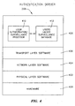
- FIG. 4 illustrates an exemplary authentication server according to an embodiment of the present invention.
- authentication server generally designated 208 includes hardware 400 , physical layer software 402 , network layer software 404 , and transport layer software 406 . These layers are preferably the same or similar to the corresponding layers 300 through 306 described with respect to the proxy 206 illustrated in Figure 3. Accordingly, a description of these layers is not repeated herein.
- authentication server 208 includes application layer software 408 for performing user authentication and surveillance identification.
- application layer software 408 includes user authenticator/surveillance processor 410 and a users-under surveillance-database 412 .
- User authenticator/surveillance processor 410 receives user authentication information from authentication server interface 314 illustrated in Figure 3 and performs user authentication based on this information.
- user authenticator/surveillance processor 410 can receive user IDs and passwords from authentication server interface 314 illustrated in Figure 3.
- User authenticator/surveillance processor 410 can also access the users-under-surveillance database 412 to determine whether a user is under surveillance. If user authenticator/surveillance processor 410 determines that a user is under surveillance, user authenticator/surveillance processor 410 preferably notifies proxy 206 of this fact, e.g., by sending a message to authentication interface 314 .
- Figure 5 illustrates an exemplary policy server according to an embodiment of the present invention.
- policy server generally designated 214 includes hardware 500 , physical layer software 502 , network layer software 504 , and transport layer software 506 . These layers contain similar functionality to those described with respect to Figure 3, and a description thereof is therefore not repeated herein.
- Application layer software 508 includes router resource/surveillance controller 510 .
- Router resource/surveillance controller 510 controls router bandwidth, e.g., by implementing a queue management procedure, and also controls surveillance.
- router resource/surveillance controller 510 can receive notification from policy server 214 that an end user is under surveillance. The notification can include media stream identification information for incoming and outgoing media streams to and from the end user under surveillance.
- Router resource/surveillance controller 510 can forward this information to an edge router so that the media stream can be copied or recorded.
- Router resource/surveillance controller 510 can also communicate media stream decoding information to edge router 212 to enable decoding of the media stream
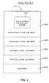
- FIG. 6 illustrates an exemplary embodiment of an edge router according to the present invention.
- edge router generally designated 212 includes hardware 600 , physical layer software 602 , network layer software 604 , and transport layer software 606 . These layers are preferably similar or identical in function to those described with respect to Figure 3, and description thereof is therefore not repeated herein.
- edge router 212 also includes application layer software 608 .
- Application layer software 608 includes media stream controller/copier 610 .
- Media stream controller/copier 610 routes the incoming and outgoing media stream to and from end user devices, such as end user device 200 to which the edge router is connected.
- media stream controller/copier 610 copies the media stream and sends copies of the media stream to recording device 210 .
- Media stream controller/copier 610 can also communicate media stream decoding information to recording device 210 to enable decoding of the media stream.
- the present invention can be used to perform IP network surveillance of IP telephone calls originating from an IP network or from the public switched telephone network (PSTN).
- Figures 7(a) - 7(c) illustrate methods and systems for IP network surveillance of a PSTN to IP telephone call.
- the examples illustrated in Figure 7(a) - 7(c) are explained in the context of MGCP call signaling, although the present invention is not limited to using MGCP call signaling.
- any other suitable call signaling protocol such as H.323, can be used.
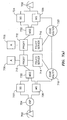
- Figure 7(a) is a block diagram illustrating the network entities that can be involved in a PSTN to IP telephone call.
- a first end user device 700 initiates a call to a second end user device 702 .
- First end user device 700 can be a traditional PSTN telephone.
- Second end user 702 can be an IP telephone adapted to send and receive audio over an IP network.
- SSP service switching point
- monitoring call signaling and media stream information to and from end user 702 can be accomplished using authentication servers 706 and 708 , proxies 710 and 712 , policy servers 714 and 716 and edge routers 718 and 720 .
- the remaining elements illustrated in Figure 7(a) are adapted to perform call signaling and media stream communication function over a packet based network such as an IP network.
- the remaining elements are media gateway control protocol (MGCP) elements.
- MGCP media gateway control protocol
- signaling gateways 722 and 724 encapsulate and unencapsulate call signaling messages to and from end users devices 700 and 702 , respectively, for transmission over a packet based network, such as an IP network.
- media gateways 726 and 728 encapsulate and unencapsulate the media stream between end user 700 and 702 .
- Media gateway controllers 730 and 732 control media gateways 726 and 728 , respectively, e.g., using MGCP events.
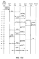
- FIG. 7(b) illustrates an exemplary call flow diagram for a call between end user 700 and end user 702 .
- end user 700 dials the telephone number of end user device 702 (illustrated in Figure 7(a)) and the dialed digits are communicated to SSP 704 .
- SSP 704 formulates and initial address message (IAM) and transmits the IAM to signaling gateway 722 .
- the IAM message is an ISDN setup (ISUP) message used to request a call.
- ISUP ISDN setup
- signaling gateway 722 encapsulates the IAM message in an IP packet and forwards the IAM message to media gateway controller 730 .
- media gateway controller 730 transmits an ADD message to media gateway 726 .
- the ADD message instructs media gateway 726 as to how to set up the interface for receiving the media stream.
- media gateway 726 transmits an accept (ACPT) message to media gateway controller 730 .
- the ACPT message from media gateway 726 includes the media flow IP address and port number associated with the gateway 726 for receiving the media stream from media gateway 728 and end user device 702 for the call.
- media gateway controller 730 transmits an INVITE message to proxy server 710 .
- the INVITE message is a Session Initiation Protocol (SIP) message used to invite the called party to join a call with the calling party.
- SIP Session Initiation Protocol
- the INVITE message includes the media flow IP address and port number on media gateway 726 for end user 700 . It is this IP address and port number that can be used to record media stream information from end user device 702 .
- the INVITE message also includes identification information for the called and calling parties.
- An example of an INVITE message is as follows:
- Lines 2-8 are the general header for the INVITE message.
- the "From” general header field indicates the initiator of the INVITE message. In the illustrated message, the initiator is "user_1@server_1.network_1.com”.
- the "To” general header field indicates the recipient of the INVITE message. In the illustrated message, the recipient is "user_2@server_2.network_2.com”.
- the information from the "From" and “To” fields can be used to determine whether user 1, user 2, or both are under surveillance. The signaling required to perform authentication will be discussed in more detail below.
- the call-ID general header field uniquely identifies an invitation for all registrations of a particular client.
- the call-ID is "125".
- the host is "proxy_1.network_1.com”.
- the call-ID "125” uniquely identifies the call requested by the INVITE message within the domain proxy_1.network_1.com.
- the call-ID can be used to identify call signaling messages to or from a user under surveillance for a particular call. The signaling required for recording call signaling messages will be discussed in more detail below.
- the Cseq general header field indicates the command sequence number for the INVITE message.
- the command sequence number is "225". The sequence number is used by SIP proxy servers to identify and order SIP messages.
- Lines 6 and 7 of the INVITE message are the entity-header of the INVITE message.
- the content-type entity header field indicates the media type of the message body sent to the recipient.
- the media type is "application/sdp", indicating that the message body contains Session Description Protocol (SDP) information.
- the content length entity header field indicates the size of the message body in decimal number of octets, sent to the recipient.
- the content length is specified as "190”, indicating that the message body contains 190 octets of information.
- the session ID in the origin field is "1". Thus number, when combined with the remaining parts of the origin field uniquely identifies the session.
- the network part of the origin field is "IN”, indicating Internet type.
- the address type part of the origin field is "IP4", indicating Internet protocol version 4.
- the address part of the origin field is a globally unique address for the machine that initiated the request. In the illustrated message, the address is "1.1.1.2", which can be the IP address of MGC 730 .
- connection data field of the IP address contains connection data for the message.
- the connection data is the IP address for the incoming media stream from end user device 702 to end user device 700 .
- This IP address can be communicated to the edge router for an end user to allow the edge router to identify and copy the media stream to an end user under surveillance. The signaling for communicating the media stream IP address to the edge router of an end user under surveillance will be discussed in more detail below.
- the transport protocol is "RTP/AVP", indicating that the Realtime Protocol using the Audio/Video profile will be used.
- PCM mu-law pulse-code-modulation
- proxy server 710 contacts authentication server 706 (illustrated in Figure 7(a)) to authenticate end user device 700 and end user device 702 .
- authentication server 706 preferably determines whether end user device 700 or end user device 702 is under surveillance.
- Figure 7(c) illustrates exemplary steps that can be performed by authentication server 706 and proxy 710 to determine whether either of the end user devices is under surveillance.
- proxy 710 transmits the authentication request to authentication server 706 .
- authentication server 706 determines whether either of the end users is under surveillance. For example, authentication server 706 can compare the user identification information extracted from the "To" and "From" fields of the INVITE message to entries in the users-under-surveillance-database described with respect to Figure 4. Alternatively, user identification can be extracted from other fields in the INVITE message, such as the Session ID field. Any manner of identifying an end user or an end user device from the fields of a call signaling message, such as an INVITE message, is intended to be within the scope of the invention.
- authentication server 706 transmits a response to proxy server 710 . If authentication server 706 determines that either of the end users is under surveillance, the response from authentication server 706 can include such an indication.
- proxy server 710 in response to receiving notification that end user 702 is under surveillance, proxy server 710 identifies, copies, and sends call signaling information to or from end user 700 with regard to the present call to a recording device. This function can be performed by the call signaling message processor, for example, as described with respect to Figure 3.
- Proxy server 710 then sends the media flow IP address and media stream decoding information to policy server 714 ( ST6 ). Policy server 710 controls edge router 712 to copy the media stream to or from the- specified address (step ST7 ). Edge router 718 copies the media stream information to or from the specified IP address and forwards the media stream information to a recording device ( ST8 ). Edge router 718 can also communicate the media stream decoding information to the recording device to enable decoding of the media stream.
- the present invention is not limited to having the proxy server forward the media stream identification and decoding information to the policy server.
- the proxy server can forward the media stream identification information to the authentication server, and the authentication server can communicate the media stream identification and decoding information to the policy server when the authentication server determines that an end user is under surveillance. Either method is intended to be within the scope of the invention.
- proxy 710 may extract media stream identification information and media stream decoding information from call signaling messages transmitted between end user device 700 and end user device 702 .
- proxy 710 may forward copies of call signaling information between end users to a recording device without extracting the media stream decoding information.
- the recording device or other law-enforcement-controlled entity may extract the media stream decoding information from the recorded call signaling messages or from the media stream.
- proxy 712 of the called end user responds to the INVITE message by sending a TRYING message to proxy 710 , and proxy 710 forwards the TRYING message to MGC 730 .
- proxy 712 sends a RINGING message to proxy 710 , which indicates that end user 702 is being alerted.
- Proxy 710 forwards the RINGING message to media gateway controller 730 .
- media gateway controller 730 transmits an encapsulated address complete (ACM) message to signaling gateway 722 .
- signaling gateway 722 forwards the ACM message to SSP 704 .
- the ACM message indicates to SSP 704 that the called end user is being alerted.
- media gateway controller 730 sends a MODIFY message to media gateway 726 .
- media gateway responds by sending an ACCEPT (ACPT) message to media gateway controller 730 .
- ACPT ACCEPT
- media gateway 726 applies a ringback signal, which passes through SSP 704 , to end user device 700 .
- proxy 712 sends an OK message to proxy 710 .
- Proxy 710 forwards the OK message to MGC 710 .
- the OK message includes the IP address of the end user device receiving the call, i.e., end user device 702 .
- This IP address like the media flow IP address transmitted to proxy server 710 , can be used to record the media flow from the called party to the calling party.
- proxy server 712 could transmit the media flow IP address for end user 702 to policy server 716 . Policy server 716 would then forward the IP address to edge router 720 .
- media gateway controller 730 sends an ANSWER (ANM) message to SG 722 .
- signaling gateway 722 forwards the ANM message to SSP 704 indicating that the call has been answered.
- ANM ANSWER
- SSP 704 indicating that the call has been answered.
- a conversation can occur between end user devices 700 and 702 .
- the media stream is transmitted between edge routers 718 and 720 . If either user is under surveillance, either or both edge routers can send a copy of the media stream information to a recording device, as described above.
- proxy 710 , proxy 712 , or both forward copies of call signaling messages, such as SIP messages, to the recording device.
- the present invention provides a reliable method of performing surveillance of a PSTN to IP telephone call when either the PSTN end user, the IP end user, or both are under surveillance.
- Figure 8(a) illustrates methods and systems for IP network surveillance according to an embodiment of the present invention for an IP to IP telephone call.
- end user device A 800 places a call to end user device C 802 .
- the upper portion of Figure 8(a) illustrates signaling layer communications, such as SIP communications, for end user device A 800 and end user device C 802 .
- signaling layer communications such as SIP communications
- MGCP entities and communications are omitted from Figure 8(a).
- the lower portion of Figure 8(a) illustrates media layer communications, such as media stream communications, for end user device A 800 and end user device C 802 .
- end user device A 800 sends call signaling messages to A proxy 804 to establish calls with other users.
- solid line 805 between end user device A 800 and A proxy 804 represents conventional call signaling messages transmitted from an end user device to a proxy server.
- solid line 808 between end user device C 802 and C proxy 806 represents existing call signaling messages transmitted between these devices.
- authentication server 810 communicates with A proxy 804 and C proxy 806 to authenticate the end users and determine whether the end users are under surveillance. Accordingly, dashed line 811 represents new authentication signaling messages according to an embodiment of the present invention.
- Recording device 812 records call signaling messages when end user device A 800 and/or end user device C 802 is under surveillance. Accordingly, dashed lines 816 represent new call signaling messages between proxy servers and a recording device according to an embodiment of the present invention.
- dashed lines 830 represent communication between proxy servers 804 and 806 and policy server 819 to indicate that one of the end users is under surveillance, to communicate media stream identification information to policy server 819 , and to communicate media stream decoding information to policy server 819 .
- dashed line 820 can represent communication of media stream identification information, media stream decoding information, and information indicating that one of the end users is under surveillance between authentication server 810 and policy server 819 .
- media stream communications between end user device A 800 and end user device C 802 occur through A edge router 821 and C edge router 822 .
- solid lines 824 represent conventional bearer channel or media stream communications between end user device A 800 and end user device C 802 .
- Policy server 819 controls A edge router 821 and/or C edge router 822 to send copies of media stream communications between end user device A and end user device C to recording device 812 when either end user device A 800 or end user device C 802 is under surveillance.
- dashed lines 827 represent new signaling messages between policy server 819 and edge routers 821 and 822 for informing the edge routers that the end users are under surveillance.
- signals represented by dashed lines 827 can also include media stream identification information for identifying the media stream between end user device A device 800 and end user device C 802 , and media stream decoding information.
- Dashed lines 828 represent the flow of media stream information from A edge router 821 and C edge router 822 to recording device 812 according to an embodiment of the present invention.
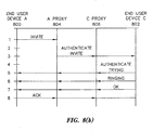
- Figure 8(b) is a call flow diagram illustrating an exemplary call flow between the entities in Figure 8(a) for establishing an IP to IP phone call between end user device A 800 and end user device C 802 .
- end user device A 800 transmits an INVITE message to A proxy 804 .
- a proxy 804 determines whether end user device A 800 or end user device C 802 is under surveillance. The steps for determining whether the end user devices are under surveillance can be similar to those illustrated in Figure 7(c) for the PSTN to IP case.
- a proxy 804 can send an authentication request to authentication server 810 (illustrated in Figure 8(a)).
- the request can include user identification information for end user device A and end user device C.
- Authentication server 810 can perform a lookup in the users-under-surveillance database based on the identification information. Authentication server 810 can then send a response to A proxy 804 indicating whether one or both of the end user devices are under surveillance. If A proxy 804 receives notification that either or both end user devices are under surveillance, A proxy 804 preferably sends copies of call signaling information between end user device A 800 and end user device C 802 to recording device 812 (illustrated in Figure 8(a)). A proxy 804 preferably also notifies policy server 819 that the end user devices are under surveillance. A proxy 804 preferably also sends media stream identification information and media stream decoding information to policy server 819 to trigger and enable copying of the media stream to end user device A 800 from end user device C 802 .
- a proxy 804 forwards the INVITE message to C proxy 806 , which forwards the INVITE message to end user device C.
- C proxy can determine whether end user device A, end user device C, or both are under surveillance, in the same manner described above with respect to line 2 of the call flow diagram.
- end user device C transmits a TRYING message to end user device A, indicating that an attempt is being made to alert end user device C.
- end user device C 802 transmits a RINGING message to end user device A indicating that end user device C 802 is being alerted.
- end user device C 802 transmits an OK message to end user device A 800 .
- the OK message includes the media flow IP address and port number and media flow decoding information for the incoming media flow for end user device C. Accordingly, this information is preferably communicated to policy server 819 (illustrated in Figure 8(a)), C edge router 822 (illustrated in Figure 8(a)), and recording device 812 (illustrated in Figure 8(a)) to enable copying and decoding of the media stream to and from end user device C 802 .
- end user device A 800 transmits an ACK message to end user device C.
- media stream communications occur between end user device A 800 and end user device C 802 through edge routers 821 and 822 (illustrated in Figure 8(a)). Because edge routers 821 and 822 have been notified that one or both of the end users are under surveillance, edge routers 821 and 822 can send copies of the media stream to recording device 812 .
- Call signaling information can be collected from proxy servers 804 and 806 .
- communications between end user device A and end user device C 800 is normal. Accordingly, embodiments of the present invention provide methods for performing IP surveillance where there is a reduced likelihood of detection by the end users.
- Embodiments of the present invention for performing IP network surveillance are useful not only to monitor telephone calls where the end user is receiving calls at his or her home terminal, but also to monitor telephone calls where calls directed to the end user surveillance are forwarded to another terminal.
- the capability to monitor forwarded calls is important in the IP environment to prevent circumvention of surveillance measures using call forwarding.
- Figure 9(a) illustrates a system for performing IP network surveillance in an IP to IP telephone call when a call to an end user is forwarded to another terminal.
- entities and signals that are labeled by the same reference numerals as the entities and signals in Figure 8(a) represent like elements. Thus, a description of these entities and signals is not repeated herein.
- New entities introduced by Figure 9 include end user device B 900 , B proxy 902 , and B edge router 904 .
- Authentication signaling between B proxy 902 and authentication server 810 is illustrated by dashed line 906 .
- Communication of call signaling information from B proxy to recording device 812 is illustrated by dashed line 908 .
- Figure 9(b) is a call flow diagram illustrating exemplary call signaling for performing IP network surveillance in the environment illustrated in Figure 9(a).
- end user device A 800 is the calling party
- end user device B 900 is the called party.
- end user device B 900 has been forwarded to end user device C 802 .
- end user device A 800 transmits an INVITE message to A proxy 804 .
- the INVITE message includes information that identifies end user device B as the called party, e.g., in the "To" field of the message.
- a proxy 804 determines whether end user device A 800 or end user device B 900 is under surveillance. The steps for determining whether the end users are under surveillance can be similar to those illustrated in Figure 7(c) for the PSTN to IP case. For example, first, A proxy 804 can send an authentication request to authentication server 810 (illustrated in Figure 9(a)). The request can include user identification information for end user device A 800 and end user device B 900 .
- Authentication server 810 can perform a lookup in the users-under-surveillance database based on the identification information. Authentication server 810 can then send a response to A proxy 804 indicating whether end user device A 800 or end user device B 900 is under surveillance. If A proxy 804 receives notification that either or both end user devices are under surveillance, A proxy 804 preferably sends copies of call signaling information between end user device A 800 and end user device B 900 to recording device 812 .
- a proxy 804 preferably also notifies policy server 819 (illustrated in Figure 9(a)) that the end users are under surveillance, sends media stream identification information, and sends media stream decoding information to policy server 819 to trigger and enable copying of the media stream between end user device A 800 and end user device B 900 .
- a proxy 804 forwards the INVITE message to B proxy 902 .
- B proxy determines that calls directed to end user device B 900 have been forwarded to end user device C 802 .
- B proxy determines whether end user device A, end user device B, end user device C, or all three end users are under surveillance. Determining whether any of the end user devices is under surveillance can be accomplished in the same manner described above with respect to line 2 of the call flow diagram.
- B proxy 902 forwards the INVITE message to C proxy 806 .
- proxy 806 can determine whether end user device A, end user device B, or end user device C is under surveillance by communicating with authentication server 810 in the manner described above. If any of the end users are determined to be under surveillance, C proxy 806 preferably also sends media stream identification and decoding information extracted from the INVITE message to policy server 819 . In line 7 of the call flow diagram, end user device C transmits the TRYNG message to end user device A, indicating that an attempt is being made to alert the user of end user device C.
- the return path between end user device C and end user device A may not include any one of or all of the edge router, the policy server, the authorization server, or the proxy server associated with end user device B, and end user device B might be under surveillance. However, because call signaling messages can be collected by the remaining proxies, a complete call record can still be obtained.
- end user device C 802 transmits a RINGING message to end user device A indicating that end user B is being alerted at end user device C.
- end user device C transmits an OK message to end user device A.
- the OK message includes the media flow IP address, port number, and media stream decoding information for the incoming media flow for end user device C at which end user B is receiving calls. Accordingly, this information is preferably communicated to policy server 819 and to C edge router 822 to enable copying and decoding of the media stream to and from end user device C 802 .
- end user device A 800 transmits an ACK message to end user device C.
- media stream communications occur between end user device A 800 and end user B, who is located at end user device C 802 . Accordingly, the media stream flows through A edge router 821 and C edge router 822 . Because the edge routers have been notified that one or both of the end users are under surveillance, the edge routers can send copies of the media stream to recording device 812 .
- the methods and systems for performing IP network surveillance according to the present invention are capable of recording both call signaling and media stream information for forwarded calls.
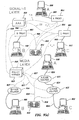
- FIG. 10(a) illustrates an exemplary operating environment in which user A 800 having an IP telephone attempts to call end user device C 802a connected to a PSTN network.
- end user device A 800 , A proxy 804 , authentication server 810 , policy-server 819 , and A edge router 821 are preferably the same as the corresponding elements described above and a description thereof is therefore not repeated herein.
- MGC proxy 1000 communicates with A proxy 804 and with IP-PSTN gateway 1001 using SIP.
- IP-PSTN gateway 1001 includes media gateway controller 1002 , signaling gateway 1003 , and media gateway 1004 .
- Signaling gateway 1003 , media gateway 1004 , and media gateway controller 1002 are the same as the correspondingly named entities described with respect to Figure 2. Accordingly, a discussion of these entities is not repeated herein.
- the PSTN network connected to end user device C includes mated pairs of signal transfer points (STPs) 1005 and 1006 , service control points (SCPs) 1007 and 1008 and SSP 1010 that communicate using the Signaling System 7 (SS7) protocol.
- STPs 1005 and 1006 are switching elements that through-switch SS7 messages based on address information in the messages.
- SCPs 1007 and 1008 are database nodes that contain call processing information for certain types of calls, such as credit card calls.
- SSP establishes media communications between end user device 802a and a remote end user device through a voice trunk.
- FIG 10(b) is a call flow diagram illustrating a method for performing IP network surveillance in the network illustrated in Figure 10(a).
- end user device A 800 transmits an INVITE message to A proxy 804 .
- a proxy 802 determines whether end user device A 800 or end user device C 802a is under surveillance.
- the steps for determining whether the end user devices are under surveillance can be similar to those illustrated in Figure 7(c) for the PSTN to IP case.
- a proxy 804 can send an authentication request to authentication server 810 (illustrated in Figure 10(a)).
- the request can include user identification information for end user device A and end user device C.
- Authentication server 810 can perform a lookup in a users-under-surveillance database based on the identification information. Authentication server 810 can then send a response to A proxy 804 indicating whether one or both of the end user devices are under surveillance. If A proxy 804 receives notification that either or both end user devices are under surveillance, A proxy 804 preferably sends copies of call signaling information between end user device A 800 and end user device C 802a to recording device 812 .
- a proxy 804 preferably also notifies policy server 819 (illustrated in Figure 10(a)) that the end user devices are under surveillance, sends media stream identification information, and sends media stream decoding information to policy server 819 to trigger and enable copying of the media stream between end user device A 800 and end user device C 802a .
- a proxy 804 forwards the INVITE message to MGC proxy 1000 , which forwards the INVITE message to IP-PSTN gateway 1001 .
- MGC proxy 1000 can determine whether end user device A, end user device C, or both are under surveillance, in the same manner described above with respect to line 2 of the call flow diagram.
- end user IP-PSTN gateway transmits a TRYING message to end user device A, indicating that an attempt is being made to alert end user device C.
- IP-PSTN gateway 1001 transmits a RINGING message to end user device A indicating that end user device C 802a is being alerted.
- IP-PSTN gateway transmits an OK message to end user device A.
- the OK message includes the media flow IP address, port number, and media flow decoding information for the incoming media flow for end user device C. Accordingly, this information is preferably communicated to policy server 819 and to C edge router 822 to enable copying and decoding of the media stream to and from IP-PSTN gateway 1001 .
- end. user device A 800 transmits an ACK message to end user device C 802a .
- media stream communications occur between end user device A 800 and end user device C 802a through edge routers 821 and 822 . Because the edge routers have been notified that one or both of the end users are under surveillance, the edge routers can send copies of the media stream to recording device 812 .
- the methods and systems for performing IP network surveillance also apply to IP-PSTN calls.
- the present invention is not limited the method for performing IP network surveillance for an IP-PSTN telephone call described with respect to Figure 10(a).
- authentication server 810 when authentication server 810 indicates that either of the end user devices is under surveillance, authentication server can inform A proxy 804 .
- a proxy 804 can then transmit a signal to SSP 1010 to trigger recording of both call signaling and media stream information to and from end user device C. Recording can be performed in a conventional manner, for example, using a magnetic tape device.
- Figure 11(a) illustrates an exemplary operating environment for embodiments of the present invention in which an IP to IP call is forwarded to a PSTN terminal.
- the network entities associated with end user device A and end user device C are the same as those described with respect to Figure 10(a). Hence, a description of these entities will not be repeated herein.
- End user device B and B proxy are the same as the corresponding entities described with respect to Figure 9(a). Hence, a description of these entities is likewise not repeated herein.
- Figure 11(b) is a call flow diagram illustrating a method for performing IP network surveillance in the operating environment illustrated in Figure 11(a).
- end user device A 800 transmits an INVITE message to A proxy 804 .
- a proxy 804 determines whether end user device A 800 or end user device B 900 (illustrated in Figure 11(a)) is under surveillance.
- the steps for determining whether the end user devices are under surveillance can be similar to those illustrated in Figure 7(c) for the PSTN to IP case.
- a proxy 804 can send an authentication request to authentication server 810 (illustrated in Figure 11(a)).
- the request can include user identification information for end user device A and end user device B.
- Authentication server 810 can perform a lookup in the users-under-surveillance database based on the identification information. Authentication server 810 can then send a response to A proxy 804 indicating whether one or both of the end users are under surveillance. If A proxy 804 receives notification that either or both end users are under surveillance, A proxy 804 preferably sends copies of call signaling information between end user device A 800 and end user device B 900 to recording device 812 . A proxy 804 preferably also notifies policy server 819 that the end users are under surveillance, sends media stream identification information, and sends media stream decoding information to policy server 819 to trigger and enable copying of the media stream between end user device A 800 and end user device C 802a .
- a proxy 804 forwards the INVITE message to B proxy 902 .
- B proxy determines that calls directed to end user device B have been forwarded to another location. B proxy can also determine whether end user device A, end user device B, end user device C, or all three end users are under surveillance. Determining whether any of the end users is under surveillance can be accomplished in the same manner described above with respect to line 2 of the call flow diagram.
- B proxy forwards the INVITE message to MGC proxy 1000
- MGC proxy forwards the INVITE message to gateway 1001 .
- MGC proxy 1000 can determine whether end user device A, end user device B, or end user device C are under surveillance by communicating with authentication server 810 in the manner described above. If any of the end users are determined to be under surveillance, MGC proxy 1000 preferably also sends media stream identification and decoding information extracted from the INVITE message to policy server 819 . In line 7 of the call flow diagram, gateway 1001 transmits the TRYNG message to end user device A, indicating that an attempt is being made to alert end user B at end user device C. The return path between end user device C and end user device A may not include any one of or all of the edge router, policy server, authorization server, or proxy server associated with end user device B. However, because call signaling messages can be collected by the remaining proxies, a complete call signaling record can be obtained.
- gateway 1001 transmits a RINGING message to end user device A indicating that the user at end user device C is being alerted.
- end gateway 1001 transmits an OK message to end user device A.
- the OK message includes the media flow IP address and port number and media flow decoding information for the incoming media flow for end user device C at which end user B is receiving calls. Accordingly, this information is preferably communicated to policy server 819 and to C edge router 822 to enable copying and decoding of the media stream to and from end user device C 802a .
- end user device A 800 transmits an ACK message to gateway 1001 .
- media stream communications occur between end user device A 800 and end user device B, who is located at end user device C 802a . Accordingly, the media stream flows through A edge router 821 (illustrated in Figure 11(a)) and C edge router 822 (illustrated in Figure 11(a)). Because edge routers 821 and 822 have been notified that one or both of the end users are under surveillance, edge routers 821 and 822 can send copies of the media stream to recording device 812 .
- the methods and systems for performing IP network surveillance according to the present invention are capable of recording both call signaling and media stream information for forwarded calls.
- the present invention can comprise a packet sniffer adapted to copy all message packets transmitted to or received from an end user under surveillance.
- a packet sniffer according to the present embodiment can be connected to the same network as the end user under surveillance.
- the packet sniffer can have an Ethernet connection to the end user's local area network. Since the packet sniffer is physically connected to an Ethernet network, the packet sniffer can receive all messages transmitted to or from network entities on the network. In order to perform surveillance, the packet sniffer can record all messages directed to or from an end user under surveillance.
- the packet sniffer can simply transmit copies of the messages to a recording device without processing the messages into call signaling or media stream sequences. The processing can be then be done by the recording device. Alternatively, the packet sniffer can assemble the call signaling and media stream information and send the assembled information to the recording device. Either method for processing the received messages is within the scope of the invention.
- RMON remote monitoring
- RMON is conventionally used for network traffic analysis, but can be used for IP network surveillance.
- RMON probes process large amounts of data and require large amounts of storage space.
- This technology can be used for packet sniffing on a high bandwidth, e.g., faster than Ethernet, connection.
- Additional monitoring software available on some LAN switches can be used for port monitoring from a VLAN perspective or perhaps the whole switch, but this monitoring is product specific. Accordingly, while it is technologically possible to perform surveillance via packet sniffing, such methods require either massive processing, storage, or product specific software. As a result, IP network surveillance through analysis of call signaling messages, as described above, is preferred.
- the examples discussed above are directed primarily to performing surveillance of IP telephone calls, the present invention is not limited to such an embodiment.
- the methods and systems described herein may be used to perform surveillance of video communications, data communications, such as e-mail communications and file downloads, and audio communications, other than voice telephone calls, that occur over an IP network.
- a surveillance order may be issued to the service provider of one end user but not necessarily to the service providers of both end users.
- the only evidence of the surveillance may be the request for authentication transmitted by the proxy server to the authentication server of the end user under surveillance as described above.
- the end user under surveillance has redirected to another location served by a different service provider, it may be necessary for the subject's proxy server to explicitly communicate this fact to an entity, e.g., a proxy server, an authentication server, a policy server, or other entity, in the originating and/or terminating network in which surveillance is required.
- end user B's service provider may be aware of the surveillance order.
- the calling end user i.e., end user A
- the called end user i.e., end user C
- One possible solution to this problem is to have the subject's proxy, e.g., B proxy 902 illustrated in Figure 9a , upon determining that the origination point and the termination point is outside of the current server's network, may send a message to either or both end point proxies, informing them of the surveillance.
- This information is preferably not part of the communications signaling, since the end user may have access to the call signaling information.
- every licensed service provider could have an exhaustive list of everyone under surveillance. Either possibility is within the scope of the invention.
Landscapes
- Engineering & Computer Science (AREA)
- Signal Processing (AREA)
- Computer Networks & Wireless Communication (AREA)
- Computer Security & Cryptography (AREA)
- Technology Law (AREA)
- Computer Hardware Design (AREA)
- Computing Systems (AREA)
- General Engineering & Computer Science (AREA)
- Multimedia (AREA)
- Data Exchanges In Wide-Area Networks (AREA)
Applications Claiming Priority (2)
| Application Number | Priority Date | Filing Date | Title |
|---|---|---|---|
| US472377 | 1990-02-01 | ||
| US47237799A | 1999-12-23 | 1999-12-23 |
Publications (3)
| Publication Number | Publication Date |
|---|---|
| EP1111892A2 true EP1111892A2 (de) | 2001-06-27 |
| EP1111892A3 EP1111892A3 (de) | 2003-11-05 |
| EP1111892B1 EP1111892B1 (de) | 2007-10-24 |
Family
ID=23875277
Family Applications (1)
| Application Number | Title | Priority Date | Filing Date |
|---|---|---|---|
| EP00311068A Expired - Lifetime EP1111892B1 (de) | 1999-12-23 | 2000-12-12 | Verfahren und Vorrichtungen zur Überwachung eines Internetprotokollnetzwerkes |
Country Status (3)
| Country | Link |
|---|---|
| EP (1) | EP1111892B1 (de) |
| CA (1) | CA2326246C (de) |
| DE (1) | DE60036848T2 (de) |
Cited By (16)
| Publication number | Priority date | Publication date | Assignee | Title |
|---|---|---|---|---|
| EP1289191A1 (de) * | 2001-09-03 | 2003-03-05 | Agilent Technologies, Inc. (a Delaware corporation) | Überwachung von Kommunikationsnetzen |
| EP1307036A1 (de) * | 2001-10-29 | 2003-05-02 | TELEFONAKTIEBOLAGET LM ERICSSON (publ) | Anrufüberwachung in einem Kommunikationssystem |
| WO2003058914A1 (en) * | 2002-01-08 | 2003-07-17 | Siemens Plc | Method and system for recording a communication signal in a packet network |
| EP1345395A1 (de) * | 2002-03-15 | 2003-09-17 | Alcatel | Verfahren zum Abhören von Kommunikationsverbindungen |
| EP1388972A1 (de) * | 2002-08-07 | 2004-02-11 | Huawei Technologies Co., Ltd. | Mehrschichtiges Verfahren zum Verwalten von Multicast Teilnehmern |
| EP1389864A1 (de) * | 2002-08-13 | 2004-02-18 | Nortel Networks Limited | Netzwerkarchitektur zur Unterstützung von legalen Abfangen von einer Netzwerkkommunikation |
| EP1389862A1 (de) * | 2002-08-08 | 2004-02-18 | Alcatel | Legales Abfangen für VOIP Anrufe in einem IP-Fernmeldenetz |
| EP1460825A4 (de) * | 2001-12-27 | 2005-05-04 | Matsushita Electric Industrial Co Ltd | Austauschsystem und kommunikationsaufzeichnungsverfahren |
| EP1528774A1 (de) * | 2003-10-30 | 2005-05-04 | Alcatel | Verfahren und System zur gesetzlichen Überwachung von Anrufen |
| EP1276294A3 (de) * | 2001-07-11 | 2005-06-01 | Siemens Aktiengesellschaft | Verfahren zur Unterstützung von Dienstgütemerkmalen in heterogenen Kommunikationsnetzen |
| EP1592215A1 (de) * | 2004-04-30 | 2005-11-02 | Lucent Technologies Inc. | Verfahren und Gerät zur Überwachung von Sprache-über-Internet-Protokoll-Kommunikationen |
| WO2007113068A1 (de) | 2006-03-30 | 2007-10-11 | Nokia Siemens Networks Gmbh & Co. Kg | Verfahren für lawful interception bei anrufweiterschaltung in einem paketorientierten telekommunikationsnetz |
| EP1988547A4 (de) * | 2006-02-14 | 2009-07-15 | Huawei Tech Co Ltd | Verfahren und system zum implementieren einer multimedia-aufzeichnung und medienressourcen-handhabungseinrichtung |
| WO2012168712A1 (en) * | 2011-06-07 | 2012-12-13 | Metaswitch Networks Ltd | Capturing media data on redirected calls for a multi - service telephony user |
| US10462190B1 (en) | 2018-12-11 | 2019-10-29 | Counter Link LLC | Virtual ethernet tap |
| CN114629881A (zh) * | 2020-12-14 | 2022-06-14 | 中兴通讯股份有限公司 | 一种sip网元多地址学习方法及装置、信令监测系统 |
Families Citing this family (3)
| Publication number | Priority date | Publication date | Assignee | Title |
|---|---|---|---|---|
| CN100373887C (zh) * | 2002-09-13 | 2008-03-05 | 华为技术有限公司 | 使用四层的端口号掩码对数据流分类的方法 |
| US9807124B2 (en) | 2014-09-08 | 2017-10-31 | Level 3 Communications, Llc | Lawful intercept provisioning system and method for a network domain |
| US12284582B2 (en) | 2022-03-15 | 2025-04-22 | T-Mobile Usa, Inc. | Inaudibly notifying a caller of a status of an open-line call |
Family Cites Families (3)
| Publication number | Priority date | Publication date | Assignee | Title |
|---|---|---|---|---|
| US5978450A (en) * | 1997-03-28 | 1999-11-02 | Bell Atlantic Network Services, Inc. | Personal dial tone |
| US6047060A (en) * | 1998-02-20 | 2000-04-04 | Genesys Telecommunications Laboratories, Inc. | Method and apparatus for enabling full interactive monitoring of calls to and from a call-in center |
| US6498843B1 (en) * | 1998-04-22 | 2002-12-24 | General Dynamics Government Systems Corporation | Method and system for intercepting and monitoring signals in a network |
-
2000
- 2000-11-16 CA CA002326246A patent/CA2326246C/en not_active Expired - Fee Related
- 2000-12-12 EP EP00311068A patent/EP1111892B1/de not_active Expired - Lifetime
- 2000-12-12 DE DE60036848T patent/DE60036848T2/de not_active Expired - Lifetime
Cited By (25)
| Publication number | Priority date | Publication date | Assignee | Title |
|---|---|---|---|---|
| US7359320B2 (en) | 2001-07-11 | 2008-04-15 | Siemens Aktiengellschaft | Method for supporting quality of service features in heterogeneous communications networks |
| EP1276294A3 (de) * | 2001-07-11 | 2005-06-01 | Siemens Aktiengesellschaft | Verfahren zur Unterstützung von Dienstgütemerkmalen in heterogenen Kommunikationsnetzen |
| EP1289191A1 (de) * | 2001-09-03 | 2003-03-05 | Agilent Technologies, Inc. (a Delaware corporation) | Überwachung von Kommunikationsnetzen |
| EP1667414A3 (de) * | 2001-10-29 | 2006-06-14 | Telefonaktiebolaget LM Ericsson (publ) | Gesetzliche Überwachung von komprimierten Sprachanrufen |
| EP1307036A1 (de) * | 2001-10-29 | 2003-05-02 | TELEFONAKTIEBOLAGET LM ERICSSON (publ) | Anrufüberwachung in einem Kommunikationssystem |
| CN100438541C (zh) * | 2001-12-27 | 2008-11-26 | 松下电器产业株式会社 | 交换系统以及通信记录方法 |
| EP1460825A4 (de) * | 2001-12-27 | 2005-05-04 | Matsushita Electric Industrial Co Ltd | Austauschsystem und kommunikationsaufzeichnungsverfahren |
| WO2003058914A1 (en) * | 2002-01-08 | 2003-07-17 | Siemens Plc | Method and system for recording a communication signal in a packet network |
| EP1345395A1 (de) * | 2002-03-15 | 2003-09-17 | Alcatel | Verfahren zum Abhören von Kommunikationsverbindungen |
| CN100448218C (zh) * | 2002-03-15 | 2008-12-31 | 阿尔卡特公司 | 收听呼叫的方法、收听服务器、呼叫控制服务器和ip路由器 |
| US7676025B2 (en) | 2002-03-15 | 2010-03-09 | Alcatel | Method of listening in to calls |
| EP1388972A1 (de) * | 2002-08-07 | 2004-02-11 | Huawei Technologies Co., Ltd. | Mehrschichtiges Verfahren zum Verwalten von Multicast Teilnehmern |
| US7548966B2 (en) | 2002-08-07 | 2009-06-16 | Huawei Technologies Co., Ltd. | Multi-layer user management method for multicasting proxy |
| EP1389862A1 (de) * | 2002-08-08 | 2004-02-18 | Alcatel | Legales Abfangen für VOIP Anrufe in einem IP-Fernmeldenetz |
| EP1389864A1 (de) * | 2002-08-13 | 2004-02-18 | Nortel Networks Limited | Netzwerkarchitektur zur Unterstützung von legalen Abfangen von einer Netzwerkkommunikation |
| EP1528774A1 (de) * | 2003-10-30 | 2005-05-04 | Alcatel | Verfahren und System zur gesetzlichen Überwachung von Anrufen |
| US7570743B2 (en) | 2004-04-30 | 2009-08-04 | Alcatel-Lucent Usa Inc. | Method and apparatus for surveillance of voice over internet protocol communications |
| EP1592215A1 (de) * | 2004-04-30 | 2005-11-02 | Lucent Technologies Inc. | Verfahren und Gerät zur Überwachung von Sprache-über-Internet-Protokoll-Kommunikationen |
| EP1988547A4 (de) * | 2006-02-14 | 2009-07-15 | Huawei Tech Co Ltd | Verfahren und system zum implementieren einer multimedia-aufzeichnung und medienressourcen-handhabungseinrichtung |
| US8498517B2 (en) | 2006-02-14 | 2013-07-30 | Huawei Technologies Co., Ltd. | Method and system of implementing multimedia recording and media resource handling device |
| WO2007113068A1 (de) | 2006-03-30 | 2007-10-11 | Nokia Siemens Networks Gmbh & Co. Kg | Verfahren für lawful interception bei anrufweiterschaltung in einem paketorientierten telekommunikationsnetz |
| WO2012168712A1 (en) * | 2011-06-07 | 2012-12-13 | Metaswitch Networks Ltd | Capturing media data on redirected calls for a multi - service telephony user |
| US9729713B2 (en) | 2011-06-07 | 2017-08-08 | Metaswitch Networks Ltd | Method and system for processing media data for later access |
| US10462190B1 (en) | 2018-12-11 | 2019-10-29 | Counter Link LLC | Virtual ethernet tap |
| CN114629881A (zh) * | 2020-12-14 | 2022-06-14 | 中兴通讯股份有限公司 | 一种sip网元多地址学习方法及装置、信令监测系统 |
Also Published As
| Publication number | Publication date |
|---|---|
| CA2326246A1 (en) | 2001-06-23 |
| CA2326246C (en) | 2005-04-05 |
| DE60036848D1 (de) | 2007-12-06 |
| DE60036848T2 (de) | 2008-08-21 |
| EP1111892B1 (de) | 2007-10-24 |
| EP1111892A3 (de) | 2003-11-05 |
Similar Documents
| Publication | Publication Date | Title |
|---|---|---|
| EP1111892B1 (de) | Verfahren und Vorrichtungen zur Überwachung eines Internetprotokollnetzwerkes | |
| US10721276B2 (en) | Providing SIP signaling data for third party surveillance | |
| US7167468B2 (en) | Internet protocol telephony voice/video message deposit and retrieval | |
| US8607323B2 (en) | Method for providing media communication across firewalls | |
| US6757823B1 (en) | System and method for enabling secure connections for H.323 VoIP calls | |
| US6870817B2 (en) | Method and apparatus for monitoring calls over a session initiation protocol network | |
| US8634412B2 (en) | Session initiation protocol (SIP) message incorporating a multi-purpose internet mail extension (MIME) media type for describing the content and format of information included in the SIP message | |
| CN1640110B (zh) | 在分组交换电话网络中进行计算机电话集成的装置和方法 | |
| US7646761B2 (en) | Integrating multimedia capabilities with legacy networks | |
| US20140241342A1 (en) | Emergency services for packet networks | |
| CN100531074C (zh) | 一种ip多媒体子系统网络合法监听的方法和系统 | |
| JP2002522962A (ja) | ネットワークリソースの割当て方法 | |
| US7069432B1 (en) | System and method for providing security in a telecommunication network | |
| US8539552B1 (en) | System and method for network based policy enforcement of intelligent-client features | |
| US7738638B1 (en) | Voice over internet protocol call recording | |
| JP2008538470A (ja) | 未承諾の音声情報の送信に対抗する方法 | |
| CN100401692C (zh) | 分组语音网络的监听方法 | |
| US20090016324A1 (en) | Method and Gateway for Connecting IP Communication Entities via a Residential Gateway |
Legal Events
| Date | Code | Title | Description |
|---|---|---|---|
| PUAI | Public reference made under article 153(3) epc to a published international application that has entered the european phase |
Free format text: ORIGINAL CODE: 0009012 |
|
| AK | Designated contracting states |
Kind code of ref document: A2 Designated state(s): AT BE CH CY DE DK ES FI FR GB GR IE IT LI LU MC NL PT SE TR |
|
| AX | Request for extension of the european patent |
Free format text: AL;LT;LV;MK;RO;SI |
|
| PUAL | Search report despatched |
Free format text: ORIGINAL CODE: 0009013 |
|
| RAP1 | Party data changed (applicant data changed or rights of an application transferred) |
Owner name: NORTEL NETWORKS LIMITED |
|
| AK | Designated contracting states |
Kind code of ref document: A3 Designated state(s): AT BE CH CY DE DK ES FI FR GB GR IE IT LI LU MC NL PT SE TR |
|
| AX | Request for extension of the european patent |
Extension state: AL LT LV MK RO SI |
|
| RIC1 | Information provided on ipc code assigned before grant |
Ipc: 7H 04L 29/06 B Ipc: 7H 04M 3/22 B Ipc: 7H 04M 7/00 A |
|
| 17P | Request for examination filed |
Effective date: 20040406 |
|
| AKX | Designation fees paid |
Designated state(s): DE FR GB |
|
| GRAP | Despatch of communication of intention to grant a patent |
Free format text: ORIGINAL CODE: EPIDOSNIGR1 |
|
| GRAS | Grant fee paid |
Free format text: ORIGINAL CODE: EPIDOSNIGR3 |
|
| GRAA | (expected) grant |
Free format text: ORIGINAL CODE: 0009210 |
|
| AK | Designated contracting states |
Kind code of ref document: B1 Designated state(s): DE FR GB |
|
| REG | Reference to a national code |
Ref country code: GB Ref legal event code: FG4D |
|
| REF | Corresponds to: |
Ref document number: 60036848 Country of ref document: DE Date of ref document: 20071206 Kind code of ref document: P |
|
| ET | Fr: translation filed | ||
| PLBE | No opposition filed within time limit |
Free format text: ORIGINAL CODE: 0009261 |
|
| STAA | Information on the status of an ep patent application or granted ep patent |
Free format text: STATUS: NO OPPOSITION FILED WITHIN TIME LIMIT |
|
| 26N | No opposition filed |
Effective date: 20080725 |
|
| PGFP | Annual fee paid to national office [announced via postgrant information from national office to epo] |
Ref country code: GB Payment date: 20141124 Year of fee payment: 15 |
|
| PGFP | Annual fee paid to national office [announced via postgrant information from national office to epo] |
Ref country code: FR Payment date: 20141124 Year of fee payment: 15 |
|
| PGFP | Annual fee paid to national office [announced via postgrant information from national office to epo] |
Ref country code: DE Payment date: 20141222 Year of fee payment: 15 |
|
| REG | Reference to a national code |
Ref country code: DE Ref legal event code: R119 Ref document number: 60036848 Country of ref document: DE |
|
| GBPC | Gb: european patent ceased through non-payment of renewal fee |
Effective date: 20151212 |
|
| REG | Reference to a national code |
Ref country code: FR Ref legal event code: ST Effective date: 20160831 |
|
| PG25 | Lapsed in a contracting state [announced via postgrant information from national office to epo] |
Ref country code: GB Free format text: LAPSE BECAUSE OF NON-PAYMENT OF DUE FEES Effective date: 20151212 Ref country code: DE Free format text: LAPSE BECAUSE OF NON-PAYMENT OF DUE FEES Effective date: 20160701 |
|
| PG25 | Lapsed in a contracting state [announced via postgrant information from national office to epo] |
Ref country code: FR Free format text: LAPSE BECAUSE OF NON-PAYMENT OF DUE FEES Effective date: 20151231 |