EP1111784B1 - Verfahren und elektrische Vorrichtung für die leistungsfähige Generierung von Mehrfachraten-Pseudozufallsfolgen - Google Patents
Verfahren und elektrische Vorrichtung für die leistungsfähige Generierung von Mehrfachraten-Pseudozufallsfolgen Download PDFInfo
- Publication number
- EP1111784B1 EP1111784B1 EP99610079A EP99610079A EP1111784B1 EP 1111784 B1 EP1111784 B1 EP 1111784B1 EP 99610079 A EP99610079 A EP 99610079A EP 99610079 A EP99610079 A EP 99610079A EP 1111784 B1 EP1111784 B1 EP 1111784B1
- Authority
- EP
- European Patent Office
- Prior art keywords
- sequence
- value
- control signal
- select value
- basis
- Prior art date
- Legal status (The legal status is an assumption and is not a legal conclusion. Google has not performed a legal analysis and makes no representation as to the accuracy of the status listed.)
- Expired - Lifetime
Links
Images


Classifications
-
- H—ELECTRICITY
- H04—ELECTRIC COMMUNICATION TECHNIQUE
- H04J—MULTIPLEX COMMUNICATION
- H04J13/00—Code division multiplex systems
- H04J13/0007—Code type
- H04J13/0022—PN, e.g. Kronecker
-
- G—PHYSICS
- G06—COMPUTING OR CALCULATING; COUNTING
- G06F—ELECTRIC DIGITAL DATA PROCESSING
- G06F7/00—Methods or arrangements for processing data by operating upon the order or content of the data handled
- G06F7/58—Random or pseudo-random number generators
-
- H—ELECTRICITY
- H03—ELECTRONIC CIRCUITRY
- H03K—PULSE TECHNIQUE
- H03K3/00—Circuits for generating electric pulses; Monostable, bistable or multistable circuits
- H03K3/84—Generating pulses having a predetermined statistical distribution of a parameter, e.g. random pulse generators
-
- H—ELECTRICITY
- H04—ELECTRIC COMMUNICATION TECHNIQUE
- H04J—MULTIPLEX COMMUNICATION
- H04J13/00—Code division multiplex systems
- H04J13/10—Code generation
-
- H—ELECTRICITY
- H04—ELECTRIC COMMUNICATION TECHNIQUE
- H04L—TRANSMISSION OF DIGITAL INFORMATION, e.g. TELEGRAPHIC COMMUNICATION
- H04L9/00—Cryptographic mechanisms or cryptographic arrangements for secret or secure communications; Network security protocols
- H04L9/06—Cryptographic mechanisms or cryptographic arrangements for secret or secure communications; Network security protocols the encryption apparatus using shift registers or memories for block-wise or stream coding, e.g. DES systems or RC4; Hash functions; Pseudorandom sequence generators
- H04L9/065—Encryption by serially and continuously modifying data stream elements, e.g. stream cipher systems, RC4, SEAL or A5/3
- H04L9/0656—Pseudorandom key sequence combined element-for-element with data sequence, e.g. one-time-pad [OTP] or Vernam's cipher
- H04L9/0662—Pseudorandom key sequence combined element-for-element with data sequence, e.g. one-time-pad [OTP] or Vernam's cipher with particular pseudorandom sequence generator
Definitions
- the present invention relates to an electrical device for generating a multi-rate PN sequence comprising:
- the present invention also relates to a method of generating a multi-rate PN sequence comprising the step of:
- PN sequences Pseudo random noise sequences
- cryptographic applications are methods to provide confidentiality of transmitted information through the use of stream ciphers.
- PN sequences may e.g. be used as spreading sequences in spread-spectrum communications systems where they determine the hop sequence and/or the direct spreading sequence.
- a receiver of a spread-spectrum communications system will receive a digital signal/bit stream transmitted over a single carrier frequency which is combined from a digital signal/bit stream containing information such as a digitized voice and from a PN sequence used to code or encrypt the transmission.
- information such as a digitized voice
- PN sequence used to code or encrypt the transmission.
- the length of the PN sequence stream is much larger than the length of the information stream thereby, complicating identification of ciphers containing the actual information.
- the PN sequences are sometimes derived by using a maximal length polynomial. Constructions, whether hardware or software implemented, which form PN sequences, in this manner are sometimes referred to as m-sequence generators. It is well known that the randomness properties of the sequences generated by the m-sequence generators are very limited as a result of a linear relationship between the symbols of the sequence. This enables prediction of the next symbol given sufficiently many but small number of previous symbols. This is not desirable in various applications, and hence there is a need for efficient techniques to enhance the unpredictability.
- Clock control of the m-sequence generator is a well-known method that can be used to increase the unpredictability of m-sequence generators.
- the most frequent method of clock control is that of introducing two modes of operation in an m-sequence generator. In one mode the generator outputs the previously produced symbol, and in the other mode the generator outputs the next symbol from the m-sequence.
- the current mode can advantageously be determined by another PN sequence.
- Output bits generated by a clock controlled m-sequence generator form the PN sequences which are used, inter alia, to encrypt or spread an information signal.
- the abovementioned method of clock control is especially used in hardware realisations where it is easy to implement this stop-and-go method.
- the randomness properties of the resulting sequence are impaired by the fact that the output sequence contains repetitions of previous symbols.
- This may obviated by using a step-once or step-twice ( (1,2)-step) scheme, i.e. a basic m-sequence generator generates the next symbol (mode 1) or the symbol after the next symbol (mode 2), instead of the stop-and-go scheme.
- the basic m-sequence generator is required to produce symbols at twice the rate of the rate needed for output symbols.
- Known solutions for this depend on the use of a higher internal clock rate for the basic m-sequence generator or on the use of a very complex hardware realisation of clock controlled basic m-sequence generators.
- EP 0905611 A2 discloses a pseudorandom number generating method and pseudorandom number generator where a selector selects a pseudorandom number X j (a single bit) from either one of two function generator outputs on the basis of a previous pseudorandom number X j-1 .
- the two function generators output data composed of a plurality of bits corresponding to state data held in a register.
- Another selector selects one of the data outputs of the function generators on the basis of the previous pseudorandom number X j-1 and stores this in the register as state data.
- the abovementioned pseudorandom generator in EP 0905611 A2 does not disclose a clock controlled multi-rate generator and is subject to the abovementioned deterioration of unpredictability, since a clock rate twice as high as the needed output rate is needed because only one symbol is output at a time.
- US 5,878,075 discloses a method of and an apparatus for generating a pseudorandom noise sequence (PN sequence), where a bit sequence of pseudorandom numbers is augmented by a extra bit in order to comply with the Interim Standard IS-95 for implementation of CDMA (Code Division Multiple Access), where a sequence of 2 15 bits is required.
- PN sequence pseudorandom noise sequence
- Patent specification US 4,228,054 discloses a maximal length linear sequence pseudorandom noise (PN) sequence generator for generating an augmented length PN sequence of length 2 N .
- the PN generator generates a PN sequence of length 2 N-1 chips where a sequence augmenting circuit inserts at least one additional chip in the PN sequence at a predetermined position within the PN sequence so as to provide an output of an augmented PN sequence of length 2 N chips.
- a select signal (MUX SELECT) is used to select between a zero shifted version of a sequence and a shifted version of the sequence.
- Patent application WO 99/45673 discloses a pseudo-random sequence generator and method where determinations are made of compatible configurations of windmill generates for a selected windmill polynomial implemented through use of word-oriented memory elements where words stored in the memory elements are selectively outputted to form portions of a pseudo-random number sequence.
- Patent specification US 4,485,654 discloses a pseudo-random noise code generator where a modular type shift register includes a multiplexor selecting the input for every stage thereof and a flipflop whose input is the output of the multiplexer.
- the flipflop serving as the highest stage of the modular type shift register and feeding back the output thereof to each of the stages whereby it is possible to control the number of stages of the shift register in operation by address-controlling the modular type shift register.
- An object of the invention is to provide an electrical device for efficient multi-rate PN sequence generation of simplified construction which is capable of generating one or more m-sequences at a multi-rate.
- an electrical device of the aforementioned type said the device further comprising:
- the select value (M t ) is provided on the basis of a clock control value/signal (C t ) and a previously generated select value (M t-1 ).
- the step control signal (S t ) is provided on the basis of a clock control value/signal (C t ) and a previously generated select value (M t-1 ).
- the plurality of sequence values is two
- sequence generation means is a windmill polynomial sequence generator.
- Another object of the invention is to provide a method of efficient multi-rate PN sequence generation of simplified complexity which is capable of generating one or more m-sequences at a multi-rate.
- the select value (M t ) is provided on the basis of a clock control value/signal (C t ) and a previously generated select value (M t-1 ).
- the step control signal (S t ) is provided on the basis of a clock control value/signal (C t ) and a previously generated select value (M t-1 ).
- the plurality of sequence values is two
- the plurality of sequence values is generated by a windmill polynomial sequence generator.
- the present invention also relates to the use of the method and/or electrical device mentioned above in a portable device.
- the portable device is a mobile telephone.
- the reduced complexity of the hardware needed saves power which is especially important in e.g. a mobile telephone.
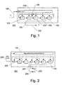
- FIG. 1 illustrates a functional block diagram of a prior art (1,2)-step clock controlled m-sequence generator (101).
- This exemplary generator (101) outputs PN sequence symbols Z t (102).
- every value in the delay element (103) is shifted to the right at each time instant, except the value of the (from left to right) first element (103) which updates to the sum (without a carry) of the values of the second and the fifth delay elements (103) by an adding element (106).
- the values of the delay elements (103) are shifted from the left to the right at each time instant, except the value of the (from left to right) first element which updates to the sum (without a carry) of the values of itself and the fifth delay elements (103) by an adding element (203), and except the third element which updates to the sum (without a carry) of the values of itself and the previous/second element (103) by an adding element (204).
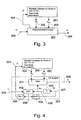
- FIG 3 schematically illustrates a combination of a windmill generator (201) and a Clock and Select system (301).
- the Clock and Select system (301), denoted CS system in the following, will be described in greater detail for one realisation in connection with Figure 4 .
- the windmill generator (201) corresponds to the one shown in Figure 2 .
- the windmill generator (201) generates blocks/tuples of size v .
- This combination of the windmill generator (201) and the CS system (301) will generate a multi-rate clock controlled m-sequence.
- the windmill generator (201) receives a step control signal S t (304) which corresponds to the next block signal (202) in Figure 2 .
- the CS system (301) is responsible for the pacing of the windmill generator (201) by providing the step control signal S t (304) and for selecting one of the two output symbols X 2i (302) and X 2i+1 (303). The selected symbol is the final output symbol Z t (305).
- the CS system (301) receives a clock control signal C t (306) which paces the CS system (301), since one set of symbol X 2i (302) and X 2i+1 (303) and thereby one output symbol Z t (305) will be generated for each value of the clock control signal C t (306).
- a clock control signal C t (306) which paces the CS system (301), since one set of symbol X 2i (302) and X 2i+1 (303) and thereby one output symbol Z t (305) will be generated for each value of the clock control signal C t (306).
- the resulting PN sequence has a high degree of unpredictability since no linear relationship between the output ciphers exists, i.e. either the next symbol or the next symbol again is output.
- the output is obtained at the same rate as the input clock rate (C t ) without the need for multiple clocks and by very little additional hardware.
- Figure 4 shows one realisation of the CS system (301) shown in Figure 3 .
- This realisation of the CS system (301) in combination with the windmill generator (201) will result in a (1,2)-step clock controlled m-sequence generator.
- selection means (401) adapted to select one of the two symbols X 2i (302) and X 2i+1 provided by the windmill generator (201). The selection is done on the basis of a previously generated select value M t-1 (406) (generated in the prior time instant as described later). If the previously generated select value M t-1 (406) is false/0 then one symbol from the windmill generator is selected, and if the value M t-1 (406) is true/1 the other symbol is selected. In the shown example, the symbol X 2i (302) is chosen for M t-1 (406) being false and X 2i+1 is chosen for M t-1 (406) being true, but it could also be vice versa. The selected symbol is the final output symbol Z t (305).
- the previously generated select value M t-1 (406) is received from a delay element D (403) which keeps a newly generated select value M t (407) for one time instant/clock cycle.
- the clock control signal value C t (306), pacing the CS system, is added by addition means (402) to the previously generated select value M t-1 (406).
- the sum (408) of C t (306) and the previously generated select value M t-1 (406) can take the values 1,2,3.
- the step control signal S t (304) is used by the windmill generator (201) to derive the two symbols X 2i (302) and X 2i+1 , as described above.
- Figure 5 shows a preferred realisation of ADD, MOD 2, and DIV 2 operations in hardware.
- the combination of ADD, MOD 2, and DIV 2 functionality may advantageously be realised in hardware by a 1 bit half-adder circuit (504).
- the clock control signal C t (305) is split into two signals, C t 0 (503) and C t 1 (502), by a logic circuit (501), preferably according to the following table: C t C t 0 C t 1 0 1 0 1 0 1 0 1 In this way C t 1 (502) is always equal to C t (305) and C t 0 (503) is always inverted to C t (305).
- C t 0 (503) is added to the previously generated select value M t-1 (406) by the 1 bit half-adder circuit (504).
- the result consists of two signals (506, 407) which represents the carry and the sum of the addition, respectively.
- the sum corresponds to a MOD 2 function since it is performed without a carry.
- the sum is the select value M t (407).
- the carry signal (506) corresponds to a DIV 2 function and is used as input together with C t 1 (502) (equal to C t (305) ) in an OR gate (505).
- the result of the OR gate (505) is the step control signal S t (304) used to control the windmill generator (201).
- Figure 6 shows a generalisation of the bi-rate method described to a quaternary-rate (1,2,3,4)-step clock controlled m-sequence generator. Shown are a windmill generator (601) and a CS system (602) which has been generalised from a bi-rate to a quaternary-rate.
- a windmill generator 601
- a CS system 602 which has been generalised from a bi-rate to a quaternary-rate.
- the CS system (602) receives the clock control signal value C t (603) now ⁇ ⁇ 1, 2, 3, 4 ⁇ and the windmill generator outputs four sequence values/symbols X 4i (604), X 4i+1 (605), X 4i+2 (606), X 4i+3 (607) on the basis of the step control signal S t (608).
- Only one of the four sequence values (604 - 607) is selected as the final output symbol Z t (609) of the PN sequence.
- the selection of one of the four symbols (604-607) in the CS system (602) is still provided on the basis of a previously generated select value M t-1 .
- Figure 7 shows a generalized embodiment of a clock controlled m-sequence generator. Shown are a windmill generator (701) and a CS system (702) which has been generalised to a N-rate, where N is at least 2.
- the CS system (702) receives the clock control signal value C t (703) now ⁇ ⁇ 1, ..., N ⁇ and the windmill generator outputs N sequence values/symbols X Ni (704), X Ni+1 (705), ..., X Ni+N-1 (706) on the basis of the step control signal S t (707).
- the degree of unpredictability may be chosen according to a specific need for a given implementation.
- Figure 8 shows a flow chart of the method according to the invention.
- the method generates a plurality of PN sequence values/symbols and selects one of these as output.
- the method is initialised at step (801).
- a select value M t is provided.
- the select value M t may be calculated on the basis of a clock control value/signal C t and a previously generated select value M t-1 .
- the clock signal C t may e.g. be provided by an external control method or hardware circuit.
- the first time a select value is calculated, the previously generated select value may have the initial value of 0 or 1.
- a control signal S t is provided.
- the generated control value S t is used to control the generation of sequence values at step (804).
- the control signal S t may be calculated on the basis of the clock control signal C t and the previously generated select value M t-1 .
- control value S t and the select value M t are calculated in this way on the basis of the same signals.
- a plurality of symbols/sequence values is generated.
- the generation of values may be done by any kind of sequence generator, e.g. a m-sequence generator, etc., but preferably the sequence generator is a windmill polynomial sequence generator. Alternatively, the generation may be done completely in software by methods corresponding to the mentioned generators.
- the number of generated sequence values may vary according to how safe the method is to be, with a concomitant increase in the computational effort.
- the number of generated values may be two or four, but any other number is just as applicable.
- next symbol and the next symbol again of the standard m-sequence generator are generated at the same time.
- the four next symbols will be generated, etc.
- the generation sequence values are controlled on the basis of the control signal S t generated at step (802).
- one of the plurality of generated sequence values is selected and output as the next symbol in the output PN sequence.
- the selection is done on the basis of the select value M t . This selection of a value between a plurality of uncorrelated sequence values greatly enhances the unpredictability of the output sequence.
- step (805) After execution of step (805) the method loops back to step (802). One loop is executed for each time step/instance.
- Figure 9 shows a preferred embodiment of the invention, which may contain the electrical device and/or use the method according to the present invention. Shown is a mobile telephone (901) having display means (904), a keypad (905), an antenna (902), a microphone (906), and a speaker (903).
- a mobile telephone 901 having display means (904), a keypad (905), an antenna (902), a microphone (906), and a speaker (903).
- Figures 10a and 10b show two exemplary implementations of a system using the method and/or device according to the invention.
- Figure 10a shows a communications system (1001) comprising a first transmitting/receiving station (1003) and a second sending/receiving station (1004) where information (1005) may be transmitted.
- the PN sequences generated by a (1,2)-step clock control m-sequence generator of an embodiment of the present invention may be used as a sub-component to encrypt information (1005) to be transmitted between the first transmitting/receiving station (1003) and the second transmitting/receiving station (1004).
- a quaternary-rate (1,2,3,4)-step clock controlled m-sequence generator or other rate generators may be provided in the system to improve the unpredictability even further.
- Figure 10b shows a transmitting/receiving station (1003) and a mobile terminal (901) which form a cellular communications system (1002).
- the information (1005) to be transmitted/received between the mobile terminal (901) and a network infrastructure (not shown) via the transmitting/receiving station (1003) may be encrypted through the use of a ciphering system that uses PN sequences generated by multi-rate clock controlled m-sequence generators.
- a quaternary-rate (1,2,3,4)-step clock controlled m-sequence generator or other rate generators may be provided in the system to improve the unpredictability even further.
Landscapes
- Engineering & Computer Science (AREA)
- Signal Processing (AREA)
- Computer Networks & Wireless Communication (AREA)
- General Physics & Mathematics (AREA)
- Physics & Mathematics (AREA)
- Theoretical Computer Science (AREA)
- Mathematical Optimization (AREA)
- General Engineering & Computer Science (AREA)
- Pure & Applied Mathematics (AREA)
- Mathematical Analysis (AREA)
- Computational Mathematics (AREA)
- Computer Security & Cryptography (AREA)
- Mobile Radio Communication Systems (AREA)
- Soundproofing, Sound Blocking, And Sound Damping (AREA)
- Measurement And Recording Of Electrical Phenomena And Electrical Characteristics Of The Living Body (AREA)
- Dc-Dc Converters (AREA)
Claims (15)
- Elektrische Vorrichtung zum Generieren einer Mehrfachraten-Pseudozufallsrauschsequenz, umfassend:- eine Sequenzgenerationseinrichtung (201; 601; 701), ausgelegt zum Ausgeben einer Vielzahl von Sequenzwerten (XNI, ..., XNI+N-1) auf der Grundlage eines Schrittsteuer-Signals (St),dadurch gekennzeichnet, dass die Vorrichtung ferner umfasst- eine Einrichtung (402; 402; 404), ausgelegt zum Bereitstellen eines Auswahlwertes (Mt) auf der Grundlage eines Taktsteuer-Wertes/-Signals (Ct) und eines vorher generierten Auswahlwertes (Mt-1),- eine Auswahleinrichtung (401), ausgelegt zum Auswählen eines aus der Vielzahl von Sequenzwerten auf der Grundlage des Auswahlwertes (Mt), und- eine Schrittsteuereinrichtung (402, 405), ausgelegt zum Bereitstellen des Schrittsteuer-Signals (St) auf der Grundlage des Taktsteuer-Wertes/-Signals (Ct) und des vorher generierten Auswahlwertes (Mt-1).
- Elektrische Vorrichtung nach Anspruch 1,
dadurch gekennzeichnet, dass- die Vielzahl von Sequenzwerten zwei ist,- der Auswahlwert (Mt) als Mt=(Ct + Mt-1) MOD 2 berechnet wird, und- das Schrittsteuersignal (St) als St=(Ct + Nt-1) DIV 2 berechnet wird, wobei Ct der bzw. das Taktsteuer-Wert/-Signal ist und Mt-1 der vorher generierte Auswahlwert (Mt-1) ist. - Elektrische Vorrichtung nach Anspruch 1,
dadurch gekennzeichnet, dass- die Vielzahl von Sequenzwerten N ist, wobei N zumindest 3 ist,- der Auswahlwert (Mt) als Mt=(Ct + Mt-1) MOD N berechnet wird, und- das Schrittsteuersignal (St) als St=(Ct + Nt-1) DIV N berechnet wird, wobei Ct der bzw. das Taktsteuer-Wert/-Signal ist und Mt-1 der vorher generierte Auswahlwert (Mt-1) ist. - Elektrische Vorrichtung nach irgendeinem der vorhergehenden Ansprüche,
dadurch gekennzeichnet, dass
die Sequenzgenerationseinrichtung (201; 601; 701) ein Windmill-Polynom-Sequenzgenerator ist. - Elektrische Vorrichtung nach Anspruch 4,
dadurch gekennzeichnet, dass
die Sequenzgenerationseinrichtung umfasst:- eine Vielzahl von Verzögerungselementen (103);- eine Schrittsteuereinrichtung (104) zum Empfangen eines nächsten Blocksteuersignals (202) als Eingabe, und- Summenelemente (203, 204),wobei jedes Verzögerungselement (103) mit einem anderen verbunden ist und zwei davon zusätzlich mit sich selbst über ein Summenelement (203, 204) verbunden sind, wobei das nächste Blocksteuersignal (202) gleich dem Schrittsteuersignal (St) ist. - Tragbare Vorrichtung (901)
dadurch gekennzeichnet, dass die elektrische tragbare Vorrichtung eine elektrische Vorrichtung nach irgendeinem der vorhergehenden Ansprüche umfasst. - Vorrichtung nach Anspruch 6,
dadurch gekennzeichnet, dass die tragbare Vorrichtung ein Mobiltelefon (901) ist. - Stationäre Kommunikationsvorrichtung,
dadurch gekennzeichnet, dass die stationäre Kommunikationsvorrichtung eine elektrische Vorrichtung nach irgendeinem der vorhergehenden Ansprüche umfasst. - Verfahren zum Generieren einer Vielfachraten-Pseudozufallsrauschsequenz, die Schritte umfassend:- Generieren einer Vielzahl von Sequenzwerten auf der Grundlage eines Schrittsteuersignals (St),dadurch gekennzeichnet, das das Verfahren ferner umfasst:- Bereitstellen eines Auswahlwertes (Mt) auf der Grundlage eines Taktsteuer-Wertes/-Signals (Ct) und eines vorher generierten Auswahlwertes (Mt-1),- Bereitstellen des Schrittsteuersignals (St) auf der Grundlage des Taktsteuer-Wertes/-Signals (Ct) und des vorher generierten Auswahlwertes (Mt-1), und- Auswählen eines aus der Vielzahl von Sequenzwerten auf der Grundlage des Auswahlwertes (Mt).
- Verfahren nach Anspruch 9,
dadurch gekennzeichnet, dass- die Vielzahl von Sequenzwerten zwei ist,- der Auswahlwert (Mt) als Mt=(Ct+Mt-1) MOD 2 berechnet wird, und- das Schrittsteuersignal (St) als St=(Ct+Mt-1) div 2 berechnet wird, wobei Ct der bzw. das Taktsteuer-Wert/-Signal ist und Mt-1 der vorher generierte Auswahlwert (Mt-1) ist. - Verfahren nach Anspruch 9,
dadurch gekennzeichnet, dass- die Vielzahl von Sequenzwerten N ist, wobei N zumindest 3 ist,- der Auswahlwert (Mt) als Mt=(Ct+Mt-1) MOD N berechnet wird, und- das Schrittsteuersignal (St) als St=(Ct+Mt-1) DIV N berechnet wird, wobei Ct der bzw. das Taktsteuer-Wert/-Signal ist und Mt-1 der vorher generierte Auswahlwert (Mt-1) ist. - Verfahren nach irgendeinem der Ansprüche 9 - 11,
dadurch gekennzeichnet, dass die Vielzahl von Sequenzwerten durch einen Windmill-Polynom-Sequenzgenerator generiert wird. - Verfahren nach irgendeinem der Ansprüche 9 - 12,
dadurch gekennzeichnet, dass das Verfahren in einer tragbaren Vorrichtung (901) verwendet wird. - Verfahren nach irgendeinem der Ansprüche 9 - 12,
dadurch gekennzeichnet, dass das Verfahren in einem Mobiltelefon (901) verwendet wird. - Verfahren nach irgendeinem der Ansprüche 9 - 12,
dadurch gekennzeichnet, dass das Verfahren in einer stationären Kommunikationsvorrichtung (901) verwendet wird.
Priority Applications (8)
| Application Number | Priority Date | Filing Date | Title |
|---|---|---|---|
| EP99610079A EP1111784B1 (de) | 1999-12-22 | 1999-12-22 | Verfahren und elektrische Vorrichtung für die leistungsfähige Generierung von Mehrfachraten-Pseudozufallsfolgen |
| DE69939220T DE69939220D1 (de) | 1999-12-22 | 1999-12-22 | Verfahren und elektrische Vorrichtung für die leistungsfähige Generierung von Mehrfachraten-Pseudozufallsfolgen |
| AT99610079T ATE403272T1 (de) | 1999-12-22 | 1999-12-22 | Verfahren und elektrische vorrichtung für die leistungsfähige generierung von mehrfachraten- pseudozufallsfolgen |
| AU23584/01A AU2358401A (en) | 1999-12-22 | 2000-11-17 | A method and an electrical device for efficient multirate pseudo random noise (pn) sequence generation |
| CN00817501.2A CN1252923C (zh) | 1999-12-22 | 2000-11-17 | 用于有效的多速率伪随机(pn)序列生成的方法和电设备 |
| PCT/EP2000/011570 WO2001047114A1 (en) | 1999-12-22 | 2000-11-17 | A method and an electrical device for efficient multirate pseudo random noise (pn) sequence generation |
| US09/742,711 US7089274B2 (en) | 1999-12-22 | 2000-12-20 | Method and an electrical device for efficient generation of multi-rate pseudo random noise (PN) sequence |
| US11/424,075 US20060242216A1 (en) | 1999-12-22 | 2006-06-14 | Method and an electrical device for efficient generation of multi-rate pseudo random noise (pn) sequence |
Applications Claiming Priority (1)
| Application Number | Priority Date | Filing Date | Title |
|---|---|---|---|
| EP99610079A EP1111784B1 (de) | 1999-12-22 | 1999-12-22 | Verfahren und elektrische Vorrichtung für die leistungsfähige Generierung von Mehrfachraten-Pseudozufallsfolgen |
Publications (2)
| Publication Number | Publication Date |
|---|---|
| EP1111784A1 EP1111784A1 (de) | 2001-06-27 |
| EP1111784B1 true EP1111784B1 (de) | 2008-07-30 |
Family
ID=8242573
Family Applications (1)
| Application Number | Title | Priority Date | Filing Date |
|---|---|---|---|
| EP99610079A Expired - Lifetime EP1111784B1 (de) | 1999-12-22 | 1999-12-22 | Verfahren und elektrische Vorrichtung für die leistungsfähige Generierung von Mehrfachraten-Pseudozufallsfolgen |
Country Status (7)
| Country | Link |
|---|---|
| US (2) | US7089274B2 (de) |
| EP (1) | EP1111784B1 (de) |
| CN (1) | CN1252923C (de) |
| AT (1) | ATE403272T1 (de) |
| AU (1) | AU2358401A (de) |
| DE (1) | DE69939220D1 (de) |
| WO (1) | WO2001047114A1 (de) |
Families Citing this family (10)
| Publication number | Priority date | Publication date | Assignee | Title |
|---|---|---|---|---|
| US6950669B2 (en) | 2000-07-05 | 2005-09-27 | Telefonaktiebolaget Lm Ericsson (Publ) | Power control algorithm for packet data based on queue/channel utilization |
| US7124155B2 (en) * | 2002-07-25 | 2006-10-17 | Koninklijke Philips Electronics N.V. | Latching electronic circuit for random number generation |
| US6771104B2 (en) | 2002-07-25 | 2004-08-03 | Koninklijke Philips Electronics N.V. | Switching electronic circuit for random number generation |
| US7047262B2 (en) | 2002-08-21 | 2006-05-16 | Koninklijke Philips Electronics N.V. | Entropy estimation and decimation for improving the randomness of true random number generation |
| US20040049525A1 (en) * | 2002-09-06 | 2004-03-11 | Koninklijke Philips Electronics N.V. | Feedback random number generation method and system |
| WO2006085038A1 (fr) * | 2005-02-14 | 2006-08-17 | France Telecom | Procede systeme et dispositif de generation d'une sequence de donnees pseudo aleatoire |
| US7673192B2 (en) * | 2005-07-20 | 2010-03-02 | Broadcom Corporation | System and method of uncorrelated code hopping in a communications system |
| KR100999260B1 (ko) * | 2008-08-22 | 2010-12-07 | 한국전자통신연구원 | Pn 코드 발생 장치 및 방법 |
| KR101091164B1 (ko) * | 2008-11-21 | 2011-12-09 | 한국전자통신연구원 | Pn 코드 발생을 개선한 능동형 rfid 장치 |
| US20110191129A1 (en) * | 2010-02-04 | 2011-08-04 | Netzer Moriya | Random Number Generator Generating Random Numbers According to an Arbitrary Probability Density Function |
Family Cites Families (18)
| Publication number | Priority date | Publication date | Assignee | Title |
|---|---|---|---|---|
| US4341925A (en) * | 1978-04-28 | 1982-07-27 | Nasa | Random digital encryption secure communication system |
| EP0246714B1 (de) * | 1984-02-06 | 1990-11-22 | British Broadcasting Corporation | Binäre Pseudo-Zufalls-Reihengeneratoren |
| US5974433A (en) * | 1984-06-29 | 1999-10-26 | Currie; Robert John | High speed M-sequence generator and decoder circuit |
| CH664056A5 (de) * | 1984-11-02 | 1988-01-29 | Borer Communications Ag | Verfahren und vorrichtung fuer die umwandlung einer digitalen datensequenz in die verschluesselte form. |
| JP2577923B2 (ja) * | 1987-07-31 | 1997-02-05 | クラリオン株式会社 | 擬似ランダム雑音符号発生器 |
| US5228054A (en) * | 1992-04-03 | 1993-07-13 | Qualcomm Incorporated | Power-of-two length pseudo-noise sequence generator with fast offset adjustment |
| US5251165A (en) * | 1992-04-09 | 1993-10-05 | James Iii J Colin | Two phase random number generator |
| EP0620518B1 (de) * | 1993-04-06 | 1999-10-06 | Hewlett-Packard Company | Verfahren und Apparat zum Erzeugen von linearen Rückführungsschieberegistersequenzen |
| US5365585A (en) * | 1993-08-30 | 1994-11-15 | Motorola, Inc. | Method and apparatus for encryption having a feedback register with selectable taps |
| US5420928A (en) * | 1994-01-25 | 1995-05-30 | Bell Communications Research, Inc. | Pseudo-random generator |
| US6014446A (en) * | 1995-02-24 | 2000-01-11 | Motorola, Inc. | Apparatus for providing improved encryption protection in a communication system |
| US5963104A (en) * | 1996-04-15 | 1999-10-05 | Vlsi Technology, Inc. | Standard cell ring oscillator of a non-deterministic randomizer circuit |
| US5864491A (en) * | 1997-11-10 | 1999-01-26 | Telefonaktiebolaget L M Ericsson | Apparatus and associated method for generating a pseudo random number |
| US6339645B2 (en) * | 1998-03-06 | 2002-01-15 | Telefonaktiebolaget Lm Ericsson (Publ) | Pseudo-random sequence generator and associated method |
| TW494306B (en) * | 1998-10-27 | 2002-07-11 | Winbond Electronics Corp | Secret code protection circuit capable of protecting read only memory data |
| US6636553B1 (en) * | 1998-12-29 | 2003-10-21 | Texas Instruments Incorporated | Pseudorandom noise generator for WCDMA |
| US6430170B1 (en) * | 1999-05-27 | 2002-08-06 | Qualcomm Inc. | Method and apparatus for generating random numbers from a communication signal |
| US6282230B1 (en) * | 1999-09-23 | 2001-08-28 | Texas Instruments Incorporated | Block pseudo-noise generating circuit |
-
1999
- 1999-12-22 EP EP99610079A patent/EP1111784B1/de not_active Expired - Lifetime
- 1999-12-22 AT AT99610079T patent/ATE403272T1/de not_active IP Right Cessation
- 1999-12-22 DE DE69939220T patent/DE69939220D1/de not_active Expired - Fee Related
-
2000
- 2000-11-17 WO PCT/EP2000/011570 patent/WO2001047114A1/en not_active Ceased
- 2000-11-17 CN CN00817501.2A patent/CN1252923C/zh not_active Expired - Fee Related
- 2000-11-17 AU AU23584/01A patent/AU2358401A/en not_active Abandoned
- 2000-12-20 US US09/742,711 patent/US7089274B2/en not_active Expired - Lifetime
-
2006
- 2006-06-14 US US11/424,075 patent/US20060242216A1/en not_active Abandoned
Also Published As
| Publication number | Publication date |
|---|---|
| CN1413381A (zh) | 2003-04-23 |
| CN1252923C (zh) | 2006-04-19 |
| ATE403272T1 (de) | 2008-08-15 |
| AU2358401A (en) | 2001-07-03 |
| WO2001047114A1 (en) | 2001-06-28 |
| US7089274B2 (en) | 2006-08-08 |
| EP1111784A1 (de) | 2001-06-27 |
| US20010005155A1 (en) | 2001-06-28 |
| US20060242216A1 (en) | 2006-10-26 |
| DE69939220D1 (de) | 2008-09-11 |
Similar Documents
| Publication | Publication Date | Title |
|---|---|---|
| US6148053A (en) | Method and apparatus for generating a stream cipher | |
| US6014446A (en) | Apparatus for providing improved encryption protection in a communication system | |
| US6834291B1 (en) | Gold code generator design | |
| US6754345B2 (en) | Pseudorandom number generation circuit and data communication system employing the same | |
| US5365585A (en) | Method and apparatus for encryption having a feedback register with selectable taps | |
| EP1429485A1 (de) | Vorrichtung und Verfahren zur Erzeugung von Verwörfelungskodes in einem UMTS Mobil-Nachrichtenübertragungssystem | |
| US7089274B2 (en) | Method and an electrical device for efficient generation of multi-rate pseudo random noise (PN) sequence | |
| US6611494B1 (en) | Orthogonal sequence generator | |
| US6813625B2 (en) | Method and device for self-clock controlled pseudo random noise (PN) sequence generation | |
| US20030053627A1 (en) | Random-number generation apparatus, random-number generation method, and random-number generation program | |
| CN101072098A (zh) | 宽带码分多址系统的长扰码序列相位偏移方法和装置 | |
| US6738413B1 (en) | Code generator, communication unit using the code generator, communication system, and code generation method | |
| HK1029685B (en) | Method and apparatus for generating a stream cipher | |
| HK1068512B (en) | Method and apparatus for generating a stream cipher |
Legal Events
| Date | Code | Title | Description |
|---|---|---|---|
| PUAI | Public reference made under article 153(3) epc to a published international application that has entered the european phase |
Free format text: ORIGINAL CODE: 0009012 |
|
| AK | Designated contracting states |
Kind code of ref document: A1 Designated state(s): AT BE CH CY DE DK ES FI FR GB GR IE IT LI LU MC NL PT SE |
|
| AX | Request for extension of the european patent |
Free format text: AL PAYMENT 19991229;LT PAYMENT 19991229;LV PAYMENT 19991229;MK PAYMENT 19991229;RO PAYMENT 19991229;SI PAYMENT 19991229 |
|
| 17P | Request for examination filed |
Effective date: 20010820 |
|
| AKX | Designation fees paid |
Free format text: AT BE CH CY DE DK ES FI FR GB GR IE IT LI LU MC NL PT SE |
|
| AXX | Extension fees paid |
Free format text: AL PAYMENT 19991229;LT PAYMENT 19991229;LV PAYMENT 19991229;MK PAYMENT 19991229;RO PAYMENT 19991229;SI PAYMENT 19991229 |
|
| RAP1 | Party data changed (applicant data changed or rights of an application transferred) |
Owner name: TELEFONAKTIEBOLAGET LM ERICSSON (PUBL) |
|
| 17Q | First examination report despatched |
Effective date: 20070413 |
|
| GRAP | Despatch of communication of intention to grant a patent |
Free format text: ORIGINAL CODE: EPIDOSNIGR1 |
|
| GRAS | Grant fee paid |
Free format text: ORIGINAL CODE: EPIDOSNIGR3 |
|
| GRAA | (expected) grant |
Free format text: ORIGINAL CODE: 0009210 |
|
| AK | Designated contracting states |
Kind code of ref document: B1 Designated state(s): AT BE CH CY DE DK ES FI FR GB GR IE IT LI LU MC NL PT SE |
|
| AX | Request for extension of the european patent |
Extension state: AL LT LV MK RO SI |
|
| REG | Reference to a national code |
Ref country code: GB Ref legal event code: FG4D |
|
| REG | Reference to a national code |
Ref country code: CH Ref legal event code: EP |
|
| REF | Corresponds to: |
Ref document number: 69939220 Country of ref document: DE Date of ref document: 20080911 Kind code of ref document: P |
|
| REG | Reference to a national code |
Ref country code: IE Ref legal event code: FG4D |
|
| LTIE | Lt: invalidation of european patent or patent extension |
Effective date: 20080730 |
|
| PG25 | Lapsed in a contracting state [announced via postgrant information from national office to epo] |
Ref country code: PT Free format text: LAPSE BECAUSE OF FAILURE TO SUBMIT A TRANSLATION OF THE DESCRIPTION OR TO PAY THE FEE WITHIN THE PRESCRIBED TIME-LIMIT Effective date: 20081230 Ref country code: NL Free format text: LAPSE BECAUSE OF FAILURE TO SUBMIT A TRANSLATION OF THE DESCRIPTION OR TO PAY THE FEE WITHIN THE PRESCRIBED TIME-LIMIT Effective date: 20080730 Ref country code: ES Free format text: LAPSE BECAUSE OF FAILURE TO SUBMIT A TRANSLATION OF THE DESCRIPTION OR TO PAY THE FEE WITHIN THE PRESCRIBED TIME-LIMIT Effective date: 20081110 |
|
| PG25 | Lapsed in a contracting state [announced via postgrant information from national office to epo] |
Ref country code: FI Free format text: LAPSE BECAUSE OF FAILURE TO SUBMIT A TRANSLATION OF THE DESCRIPTION OR TO PAY THE FEE WITHIN THE PRESCRIBED TIME-LIMIT Effective date: 20080730 Ref country code: AT Free format text: LAPSE BECAUSE OF FAILURE TO SUBMIT A TRANSLATION OF THE DESCRIPTION OR TO PAY THE FEE WITHIN THE PRESCRIBED TIME-LIMIT Effective date: 20080730 |
|
| PG25 | Lapsed in a contracting state [announced via postgrant information from national office to epo] |
Ref country code: BE Free format text: LAPSE BECAUSE OF FAILURE TO SUBMIT A TRANSLATION OF THE DESCRIPTION OR TO PAY THE FEE WITHIN THE PRESCRIBED TIME-LIMIT Effective date: 20080730 |
|
| PG25 | Lapsed in a contracting state [announced via postgrant information from national office to epo] |
Ref country code: DK Free format text: LAPSE BECAUSE OF FAILURE TO SUBMIT A TRANSLATION OF THE DESCRIPTION OR TO PAY THE FEE WITHIN THE PRESCRIBED TIME-LIMIT Effective date: 20080730 |
|
| PLBE | No opposition filed within time limit |
Free format text: ORIGINAL CODE: 0009261 |
|
| STAA | Information on the status of an ep patent application or granted ep patent |
Free format text: STATUS: NO OPPOSITION FILED WITHIN TIME LIMIT |
|
| PGFP | Annual fee paid to national office [announced via postgrant information from national office to epo] |
Ref country code: GB Payment date: 20081229 Year of fee payment: 10 |
|
| 26N | No opposition filed |
Effective date: 20090506 |
|
| PG25 | Lapsed in a contracting state [announced via postgrant information from national office to epo] |
Ref country code: MC Free format text: LAPSE BECAUSE OF NON-PAYMENT OF DUE FEES Effective date: 20081231 |
|
| REG | Reference to a national code |
Ref country code: CH Ref legal event code: PL |
|
| PG25 | Lapsed in a contracting state [announced via postgrant information from national office to epo] |
Ref country code: IT Free format text: LAPSE BECAUSE OF FAILURE TO SUBMIT A TRANSLATION OF THE DESCRIPTION OR TO PAY THE FEE WITHIN THE PRESCRIBED TIME-LIMIT Effective date: 20080730 |
|
| REG | Reference to a national code |
Ref country code: IE Ref legal event code: MM4A |
|
| REG | Reference to a national code |
Ref country code: FR Ref legal event code: ST Effective date: 20090831 |
|
| PG25 | Lapsed in a contracting state [announced via postgrant information from national office to epo] |
Ref country code: LI Free format text: LAPSE BECAUSE OF NON-PAYMENT OF DUE FEES Effective date: 20081231 Ref country code: IE Free format text: LAPSE BECAUSE OF NON-PAYMENT OF DUE FEES Effective date: 20081222 Ref country code: DE Free format text: LAPSE BECAUSE OF NON-PAYMENT OF DUE FEES Effective date: 20090701 Ref country code: CH Free format text: LAPSE BECAUSE OF NON-PAYMENT OF DUE FEES Effective date: 20081231 |
|
| PG25 | Lapsed in a contracting state [announced via postgrant information from national office to epo] |
Ref country code: SE Free format text: LAPSE BECAUSE OF FAILURE TO SUBMIT A TRANSLATION OF THE DESCRIPTION OR TO PAY THE FEE WITHIN THE PRESCRIBED TIME-LIMIT Effective date: 20081030 |
|
| PG25 | Lapsed in a contracting state [announced via postgrant information from national office to epo] |
Ref country code: FR Free format text: LAPSE BECAUSE OF NON-PAYMENT OF DUE FEES Effective date: 20081231 |
|
| PG25 | Lapsed in a contracting state [announced via postgrant information from national office to epo] |
Ref country code: LU Free format text: LAPSE BECAUSE OF NON-PAYMENT OF DUE FEES Effective date: 20081222 |
|
| PG25 | Lapsed in a contracting state [announced via postgrant information from national office to epo] |
Ref country code: CY Free format text: LAPSE BECAUSE OF FAILURE TO SUBMIT A TRANSLATION OF THE DESCRIPTION OR TO PAY THE FEE WITHIN THE PRESCRIBED TIME-LIMIT Effective date: 20080730 |
|
| GBPC | Gb: european patent ceased through non-payment of renewal fee |
Effective date: 20091222 |
|
| PG25 | Lapsed in a contracting state [announced via postgrant information from national office to epo] |
Ref country code: GR Free format text: LAPSE BECAUSE OF FAILURE TO SUBMIT A TRANSLATION OF THE DESCRIPTION OR TO PAY THE FEE WITHIN THE PRESCRIBED TIME-LIMIT Effective date: 20081031 |
|
| PG25 | Lapsed in a contracting state [announced via postgrant information from national office to epo] |
Ref country code: GB Free format text: LAPSE BECAUSE OF NON-PAYMENT OF DUE FEES Effective date: 20091222 |