BACKGROUND OF THE INVENTION
Field of the Invention:
-
The present invention relates to a drive apparatus
which is used in conjunction with a vibrating-type compressor
and is configured to supply electrical power to the
compressor by use of an inverter, and, more particularly, to
a drive apparatus for a vibrating-type compressor which
enables use of both AC and DC power sources without use of a
mechanical changeover unit.
Description of the Related Art:
-
Conventionally, an AC/DC power supply apparatus as
shown in FIG. 14 (from Japanese Patent Applications Laid-Open
(kokai) No. 7-111781) has been used as a drive apparatus for
a vibrating-type compressor. In FIG. 14, reference numeral 1
denotes a vibrating-type compressor which is used as part of
a refrigerator and operates upon receipt of a low AC voltage
of, for example, 12 V or 24 V. Reference numeral 2 denotes a
DC power source such as a battery which is mounted on a
vehicle and which outputs a DC voltage of 12 V or 24 V.
-
Alternating current from a commercial AC power source
10 is converted to direct current by an AC/DC converter 8 in
order to obtain a DC voltage equal to the DC voltage E
obtained from the battery 2. One of the DC voltage E output
from the battery and the DC voltage output from the AC/DC
converter 8 is selected by an automatic changeover unit and
is converted to an AC voltage by an inverter 6. The thus-obtained
AC voltage is supplied to the vibrating-type
compressor 1. The inverter 6 includes a first transistor 52
and a second transistor 53. These transistors 52 and 53 are
turned on alternately in order to generate the AC voltage.
-
The voltage E output from the battery 2 or the AC/DC
converter 8 is applied to the first transistor 52, whereas a
voltage -E output from a polarity inversion circuit 3 is
applied to the second transistor 53. The polarity inversion
circuit 3 includes a transistor 11, a pulse generation
circuit 12, a choke coil 13, a diode 14, and a capacitor 15
and outputs a DC voltage -E, whose polarity is opposite the
DC voltage E with respect to ground.
-
A control unit 7 variably controls the AC voltage
output from the inverter 6 by means of changing the duty
ratios of respective output waveforms of the first and second
transistors 52 and 53, to thereby change the frequency of the
AC voltage applied to the vibrating-type compressor 1.
-
The resonance frequency of the vibrating-type
compressor 1 changes depending not only on variation in load
but also on the environment in which the vibrating-type
compressor 1 is used. Therefore, if the frequency of the AC
voltage supplied to the vibrating-type compressor 1 is
maintained constant, the efficiency of the vibrating-type
compressor 1 is low. In view of this problem, there has
conventionally been used a technique for controlling the
frequency in order to minimize the difference between the
first-half peak and the second-half peak within each period
of the waveform of current flowing through the vibrating-type
compressor 1, to thereby maximize the efficiency of the
vibrating-type compressor 1.
-
A frequency following circuit 24 shown in FIG. 14
compares the average value of current flowing through a shunt
resistor 20 during a first half of a single waveform period
of an oscillation signal output from an oscillator 21 and
that during a second half of the period and outputs a control
signal for variably controlling the oscillation frequency of
the oscillator 21 such that the difference assumes a
predetermined value. Accordingly, the oscillator 21
generates a pulse signal of a frequency corresponding to the
control signal, which pulse signal is then subjected to
frequency division effected by a frequency divider 22. A
pulse signal output from the frequency divider 22 is supplied
to a transistor control circuit 23 in order to control the
first and second transistors 52 and 53. Therefore, the power
supply apparatus can generate AC voltage whose frequency
follows variation in resonance frequency caused by variation
in the load of the vibrating-type compressor 1, and thus can
drive the vibrating-type compressor 1 at maximum efficiency.
-
However, such a conventional drive apparatus may break,
because it has mechanical contacts within the automatic
changeover unit. Further, during AC input, conversion of AC
→ DC → DC → AC is performed, conversion efficiency is low,
and therefore a relatively large amount of electrical power
is consumed.
-
The inverter of the conventional drive apparatus
outputs voltage which assumes a square waveform such that the
signal assumes an on level potential during a first 180°-phase
period within each period of the waveform and an off
level potential during a second 180°-phase period within each
period of the waveform. Since the voltage applied to the
vibrating-type compressor 1 assumes not a sinusoidal waveform
but a square waveform having a 180° positive period and a
180° negative period, the operation efficiency of the
vibrating-type compressor 1 has been low.
-
When the above-described power supply apparatus is used,
an AC voltage signal whose potential changes between positive
and negative with respect to the zero potential is applied to
the vibrating-type compressor. Therefore, one terminal of
the vibrating-type compressor can be grounded, thereby
enabling a cord to be connected to the casing itself of the
vibrating-type compressor. However, a polarity inversion
circuit as described has been required, in order to enable
connection of a cord to the casing.
SUMMARY OF THE INVENTION
-
In view of the foregoing, an object of the present
invention is to provide a drive apparatus for a vibrating-type
compressor which solves the above-described problem.
-
Specifically, a first object of the present invention
is to provide a drive apparatus for a vibrating-type
compressor which employs a configuration which eliminates a
mechanical changeover unit for effecting changeover between
AC and DC and in which a commercial AC power source is
connected to an inverter unit via an AC/DC converter and a
diode OR circuit in order to eliminate mechanical contacts
from the power system to thereby decrease failure rate; i.e.,
to improve reliability.
-
A second object of the present invention is to provide
a drive apparatus for a vibrating-type compressor in which in
place of conversion of AC → DC → DC → AC, conversion of AC
→ DC → AC is effected during AC input in order to improve
conversion efficiency and reduce power consumption.
-
A third object of the present invention is to provide a
drive apparatus for a vibrating-type compressor in which
FETs disposed in the upper and lower arms of the inverter are
turned on alternately such that each FET is in an on state
over a 100° to 140° phase angle, whereby as compared with 180°
alternating supply of electricity, a wave closer to a
sinusoidal wave is supplied to the vibrating-type compressor
to thereby improve the operation efficiency of the vibrating-type
compressor itself.
-
A fourth object of the present invention is to provide
a drive apparatus for a vibrating-type compressor in which
the on period over a 100° to 140° phase angle is slightly
changed on the basis of the detected ambient temperature of
the vibrating-type compressor, whereby the efficiency is
improved further, and a valve-hitting phenomena peculiar to
vibrating-type compressors is prevented.
-
A fifth object of the present invention is to provide a
drive apparatus for a vibrating-type compressor which can
cope with a wide range of input voltage, including AC 100 V,
AC 200, DC 12 V, and DC 24 V, and which can detect a drop in
the power source voltage regardless of the input voltage
changing in the wide range.
-
A sixth object of the present invention is to provide a
drive apparatus for a vibrating-type compressor which enables
one end of the vibrating-type compressor to be grounded
without provision of a polarity inversion circuit for
generating a negative power source.
-
A seventh object of the present invention is to provide
a drive apparatus for a vibrating-type compressor which
enables reliable and accurate detection of the difference
between a first-half peak and a second-half peak of a current
waveform regardless of variation in frequency.
-
A drive apparatus for a vibrating-type compressor
according to the present invention comprises a DC power
source; an inverter 6 including switching elements and
adapted to convert direct current to alternating current
through alternating switching of the switching elements; and
an inverter control unit 7 for controlling the alternating
current supplied from the inverter 6 to the vibrating-type
compressor 1. The DC power supply comprises a first power
supply including a DC/DC converter 17 for converting direct
current from a battery to direct current of a different
voltage; a second power supply including an AC/DC converter 8
for converting alternating current from a commercial AC power
source to direct current; a diode OR circuit (diodes 25 and
26) to which are connected the first and second power
supplies; and a circuit which, upon detection of a voltage
output from the second power supply, operates to stop the
output of the first power supply via a DC/DC converter
control unit 27 for controlling the DC/DC converter 17.
-
The drive apparatus for a vibrating-type compressor
according to the present invention is preferably configured
in such a manner that one of two output terminals of the
first power supply and one of two output terminals of the
second power supply are grounded; the grounded terminals are
connected to one end of a first switching element (FET 5) of
the inverter 6, while the other end of the first switching
element (FET 5) is connected in series to one end of a second
switching element (FET 4); and a voltage output from the OR
circuit is supplied to the other end of the second switching
element (FET 4). A current detection resistor (R) is
connected in series to one of the two switching elements
(FETs 4 and 5). The connection point between the two
switching elements (FETs 4 and 5) is connected to one end of
the vibrating-type compressor 1 via a capacitor 19, and the
one end of the first switching element (FET 5) is connected
to the other end of the vibrating-type compressor 1. Thus,
the other end of the vibrating-type compressor 1 can be
grounded.
-
The inverter control unit 7 of the drive apparatus for
a vibrating-type compressor according to the present
invention is preferably configured in such a manner that the
inverter control unit 7 controls the on period within each
switching cycle of the alternating switching operation of the
switching elements within a phase angle range of 100° to 140°
and that the.on period of 100° to 140° is varied on the basis
of a detected ambient temperature of the vibrating-type
compressor.
-
The inverter control unit 7 of the drive apparatus for
a vibrating-type compressor according to the present
invention is preferably configured in order to detect and
hold a first peak of current flowing during a half cycle of
an AC output in which the first or second switching element
enters a conductive state alternately, detect a timing at
which the current reaches the held peak, and control the
timing of the alternative switching of the two switching
elements of the inverter to thereby variably control the
output frequency of the inverter.
-
Further, the drive apparatus for a vibrating-type
compressor according to the present invention preferably
comprises a constant voltage generation circuit 28 for
supplying a constant voltage for control use to the inverter
control unit 7 and the DC/DC converter control unit 27; and
an AC/DC changeover unit 9 which supplies direct current from
the battery 2 to the constant voltage generation circuit 28
and supplies output from the AC/DC converter 8 to the
constant voltage generation circuit 28 when the commercial AC
power source is connected to the drive apparatus.
BRIEF DESCRIPTION OF THE DRAWINGS
-
- FIG. 1 is a general block diagram showing a drive
apparatus for a vibrating-type compressor to which the
present invention is applied;
- FIG. 2 is a diagram showing in detail the DC/DC
converter and the DC/DC converter control unit shown in FIG.
1;
- FIG. 3 is a circuit diagram showing in detail the
frequency following circuit shown in FIG. 1;
- FIG. 4 is a chart showing voltage waveforms at
different portions of the frequency following circuit shown
in FIG. 3;
- FIG. 5 is a chart used for description of a manner of
detecting a second peak of current flowing through one FET of
the inverter;
- FIG. 6 is a circuit diagram showing the details of a
drive control circuit which constitutes the inverter control
unit shown in FIG. 1;
- FIG. 7 is a chart showing voltage waveforms at
different portions of the drive control circuit shown in FIG.
6;
- FIGS. 8A to 8E are charts exemplifying current or
voltage waveforms at different positions in the drive
apparatus for a vibrating-type compressor of the present
invention;
- FIG. 9 is a diagram showing the details of a
contactless AC/DC changeover unit and a first example of a
circuit provided for a control power supply;
- FIG. 10 is a diagram showing the details of the voltage
motor circuit shown in FIG. 9;
- FIG. 11 is a diagram showing the details of the
contactless AC/DC changeover unit and a second example of the
circuit provided for the control power supply;
- FIG. 12 is a diagram showing the details of the
contactless AC/DC changeover unit and a third example of the
circuit provided for the control power supply;
- FIG. 13 is a diagram showing the details of the
contactless AC/DC changeover unit and a fourth example of the
circuit provided for the control power supply;
- FIG. 14 is a general block diagram of a conventional
drive apparatus for a vibrating-type compressor;
- FIG. 15 is a graph showing the experimentally-obtained
relationship between on period and efficiency of the
vibrating-type compressor;
- FIG. 16 is a general block diagram showing another
drive apparatus for a vibrating-type compressor to which the
present invention is applied; and
- FIG. 17 is a circuit diagram showing the details of a
drive control circuit which constitutes the inverter control
unit shown in FIG. 16.
-
DESCRIPTION OF THE PREFERRED EMBODIMENTS
-
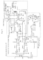
FIG. 1 is a general block diagram showing a drive
apparatus for a vibrating-type compressor to which the
present invention is applied. In FIG. 1, reference numeral 2
denotes a battery; 17 denotes a DC/DC converter; 10 denotes a
commercial AC power source; 8 denotes an AC/DC converter; 6
denotes an inverter; and 7 denotes a control unit for the
inverter 6 adapted to control the frequency of electrical
power supplied to a vibrating-type compressor 1.
-
The vibrating-type compressor 1 drives a refrigerator
mounted on, for example, a vehicle, or a freezer in the case
in which a container itself serves as a freezer. The
vibrating-type compressor 1 operates upon receipt of AC power
of a low voltage. Such a vibrating-type compressor 1
receives electrical power from the battery 2 mounted on the
vehicle when the vehicle is operated, and from the commercial
AC power source 10 when the vehicle is not operated. The
changeover between the battery 2 and the commercial AC power
source 10; i.e., changeover between AC and DC, is effected
without use of a mechanical changeover unit. A diode OR
circuit (Schottky diodes 25 and 26) provides such a
changeover function. When the commercial AC power source 10
is connected to the terminal of the drive apparatus, after
the vehicle has arrived at a parking area or other place, in
the state in which electricity is supplied from the battery 2
via the DC/DC converter 17 and the diode 26, DC voltage
output from the AC/DC converter 8 is supplied to the inverter
6 via the diode 25. At this time, as will be described in
detail hereinbelow, supply of DC voltage from the battery 2
to the inverter 6 via the DC/DC converter 17 is stopped
through control of a DC/DC converter control unit 27. The
above-described configuration eliminates mechanical contacts
from the power system to thereby decrease failure rate; i.e.,
to improve reliability. Further, since the conversion of AC
→ DC → AC performed during AC input is simpler than the
conventionally practiced conversion of AC → DC → DC → AC,
the drive apparatus has an improved conversion efficiency and
consumes less power. Reference numeral 9 denotes an AC/DC
changeover unit which selects a power source for control.
-
The DC/DC converter 17 can be configured so as to
supply a constant DC voltage to the inverter 6, whether a 12-V
battery or a 24-V battery is used as the battery 2, to
thereby supply a constant AC voltage to the vibrating-type
compressor 1. Hereinafter, a description will be given of an
exemplary case in which the battery voltage is either DC 12 V
or DC 24V. However, the circuit can be easily modified in
order to cope with an increase in the number of battery
voltages; e.g., in order to cope with DC 32 V in addition to
DC 12 V and DC 24V.
-
The output voltage of the AC/DC converter 8 is
preferably set equal to the output voltage of the DC/DC
converter 17 which is connected to the AC/DC converter 8 via
the diode OR circuit; e.g., DC 39 V. The output voltage of
the AC/DC converter 8 must be maintained constant even when
different commercial power source voltages; e.g., AC 100 V
and 200 V, are used. This can be enabled through control of
maintaining the output voltage of the AC/DC converter 8
constant. Further, in consideration that the voltage of a
commercial power source in a specific region is fixed to, for
example, AC 100 V or 200 V, an AC/DC converter having
specifications suitable for the region may be used in order
to output a constant voltage.
-
As will be described in detail, the inverter control
unit 7 receives a constant DC voltage (e.g., 12 V) from a
control-use constant voltage generation circuit 28, except in
cases in which the battery or commercial power source enters
an anomalous state. The inverter control unit 7 changes the
frequency of pulses output from a serial circuit composed of
first and second FETs 4 and 5 to thereby control the
frequency of voltage applied from the inverter 6 to the
vibrating-type compressor 1. At this time, the FETs 4 and 5
disposed in the upper and lower arms of the inverter 6 are
turned on alternately such that each FET is in an on state
over a 120° phase angle. By means of capacitance coupling,
the vibrating-type compressor 1 is supplied with an AC
voltage having a waveform which includes a 30° dead time, a
120° positive period, a 60° dead time, a 120° positive period,
and a 30° dead time in each cycle. Since the waveform is
closer to a sinusoidal waveform than is the conventional 180°
alternating supply of electricity, the operation efficiency
of the vibrating-type compressor 1 itself can be increased.
FIG. 15 is a graph showing the experimentally-obtained
relationship between on period and efficiency of the
vibrating-type compressor. As is understood from FIG. 15,
the efficiency becomes maximum in the vicinity of 120° (phase
angle period during which the vibrating-type compressor 1 is
on). As is also understood from FIG. 15, within the range of
100° to 140° (phase angle period), the efficiency is higher
than 80%, which is satisfactory.
-
Further, through an operation of detecting the ambient
temperature of the vibrating-type compressor 1 and changing
the on period slightly, the efficiency can be increased
further, and a valve-hitting phenomenon peculiar to
vibrating-type compressors can be prevented.
-
The output of the inverter 6 is supplied to the
vibrating-type compressor 1 via a capacitor 19. At this time,
a substantially constant, low DC voltage can be generated
across the capacitor in order to drive a DC fan motor 18 for
cooling the radiator of the refrigerator or freezer. One end
of the vibrating-type compressor 1 is grounded.
-
Next, the respective circuits of the drive apparatus
for a vibrating-type compressor according to the present
invention will be described in further detail.
-
FIG. 2 is a diagram showing in detail exemplary
configurations of the DC/DC converter 17 and the DC/DC
converter control unit 27 shown in FIG. 1. The DC/DC
converter 17 operates to generate a constant DC voltage, such
as DC 39 V or 48 V, whether the voltage of the connected
battery 2 is 12 V or 24 V. When an FET 32 is turned on,
energy output from the battery 2 is accumulated within an
inductance coil L2, and when the FET 32 is turned off, a
voltage equal to the sum of the terminal voltage of a
capacitor C1 and the voltage across the inductance coil L2 is
supplied to the capacitor C2. The voltage of the capacitor
C2 is supplied to the inverter 6 in the next stage. An
inductance L1 is provided to secure stable operation of the
DC/DC converter 17 even when surge voltage propagates from
the battery 2 side.
-
The FET 32 is controlled by the DC/DC converter control
unit 27 shown in FIG. 2. The control unit 27 operates while
receiving a constant voltage (12 V) from the control-use
constant voltage generation circuit 28, which will be
described later. A switching control IC 30 provided in the
control unit 27 receives, as feedback, signals indicating the
detected output voltage and current of the DC/DC converter 17.
The switching control IC 30 outputs pulses to the FET 32 as a
gate signal via a driver 31, and controls the duty ratio of
the pulses depending on the signals indicating the detected
output voltage and current. In this manner, the control unit
27 maintains the constant output voltage of the DC/DC
converter 17. A stop signal applied to the switching control
IC 30 is used in order to stop the operation of the DC/DC
converter 17 when the commercial AC power source 10 is
connected to the drive apparatus, as will be described later.
-
FIG. 3 is a circuit diagram showing in detail the
frequency following circuit 24 shown in FIG. 1. On the basis
of detected inverter current, the frequency following circuit
24 controls an oscillation circuit 34 to thereby control the
inverter 6 via a drive control circuit 33 such that the
frequency of the AC voltage supplied to the vibrating-type
compressor 1 follows the mechanical resonance frequency of
the vibrating-type compressor 1.
-
An instantaneous value of current flowing through the
inverter 6 is detected as a voltage signal by means of a
resistor R connected in series with the FET 5 of the inverter
6. This resistor R may be connected in series with the FET 4
in order to detect current flowing through the FET 4.
However, when, as shown in FIG. 3, the detection circuit is
configured to detect current flowing through the FET 5
disposed in the lower arm of the drive inverter for the
vibrating-type compressor 1, one end of the detection
resistor R can be grounded, thereby enabling use of an
ordinary amplifier in a subsequent stage in place of a
differential amplifier. Thus, stability and accuracy can be
improved. The voltage signal indicative of the detected
current is input to an amplifier 57. From the output of the
amplifier 57 is obtained a waveform indicting an
instantaneous voltage corresponding to the instantaneous
value of current flowing through the FET 5 of the inverter 6
(see P in FIG. 4).
-
The instantaneous voltage is fed to a peak-hold circuit
36. As shown in FIG. 5, a first peak value of the voltage
input via a diode D10 is held in a capacitor C6 with a
certain time constant, and the thus-held first peak voltage
is applied to a non-inverting terminal of a differential
amplifier 58. A resistor 30 for adjusting the time constant
is connected to the non-inverting terminal. When, as shown
in FIG. 5, a second peak of the instantaneous voltage input
to an inverting terminal of the differential amplifier 58
exceeds the peak value held in the capacitor C6, the
differential amplifier 58 generates an output (see Q in FIG.
4). The output is input to the oscillation circuit 34 as a
control voltage (see T in FIG. 4). A resistor R29 and a
capacitor C7 are provided in order to adjust the time
constant to thereby adjust the width of output pulses.
-
The oscillation circuit 34 can variably control the
oscillation frequency in accordance with the timing of a
signal being output from the differential amplifier 58. The
pulses output from the oscillation circuit 34 and having a
controlled frequency are input to the drive control circuit
33 to thereby control the inverter 6 to operate at a
frequency which follows the mechanical resonance frequency of
the vibrating-type compressor 1, as will be described with
reference to FIG. 6.
-
An unnecessary pulse elimination circuit 37 is provided
to reliably prevent an unnecessary narrow pulse (see Q in FIG.
4) from appearing in the output of the differential amplifier
58, which narrow pulse would otherwise be generated in the
vicinity of the first peak and would cause an erroneous
operation. Specifically, a threshold is set for a reference
triangular wave (see R in FIG. 4) output from pins 2 and 6 of
the oscillation circuit (IC) 34; and during a period in which
the level of the reference triangular wave is lower than the
threshold; i.e., a period in which an unnecessary pulse may
be generated (see S in FIG. 4), voltage is forcedly applied
to the output of the differential amplifier 58 to thereby
mask the unnecessary pulse.
-
Further, an anomalous-time stop circuit 39 is provided
in order to protect the inverter when the vibrating-type
compressor 1 enters an anomalous state. When the vibrating-type
compressor 1 enters an anomalous state and is locked,
the detected inverter current assumes a waveform which is
similar to that obtained through half-wave rectification and
which has a large magnitude (see P' in FIG. 4). Therefore,
by use of an integration circuit, the anomalous-time stop
circuit 39 detects current exceeding a threshold value, and
upon detection of such current, the anomalous-time stop
circuit 39 absorbs the reference triangular wave output from
the pins 2 and 6 of the oscillation circuit (IC) 34 in order
to stop the operation of the oscillation circuit (IC) 34, to
thereby protect the inverter.
-
The circuit illustrated in FIG. 3 has a thermo-control
unit 38. The thermo-control unit 38 compares a refrigerator
internal temperature which a user has set by use of a
temperature setting volume and an evaporator temperature
which a temperature detection thermistor detects. On the
basis of the results of comparison, the thermo-control unit
38 stops the oscillation circuit (IC) 34, by absorbing the
reference triangular wave output from the pins 2 and 6 of the
oscillation circuit (IC) 34, and resumes the operation of the
oscillation circuit (IC) 34 by permitting the oscillation of
the reference triangular wave.
-
FIG. 6 is a circuit diagram showing the details of a
drive control circuit 33 which constitutes the inverter
control unit 7 shown in FIG. 1. As have been described with
reference to FIG. 3, the output of the oscillation circuit
(IC) 34 assumes a rectangular wave of a controlled frequency
(see O in FIG. 7). The drive control circuit 33 realizes a
120° drive by use of such a rectangular wave. Specifically,
the drive control circuit 33 includes a circuit for the upper
arm for driving the FET 4 of the inverter 6, and a circuit
for the lower arm for driving the FET 5 of the inverter 6.
In the circuit for the upper arm, the rectangular wave output
from the oscillation circuit (IC) 34 is integrated by means
of an integrator, so that a sawtooth wave as shown in section
a of FIG. 7 is obtained. This sawtooth wave is compared with
a threshold value in order to obtain a pulse having a delay
of 60° with respect to the leading edge of a corresponding on
pulse, as shown in section c of FIG. 7. The thus-obtained
pulse is supplied to the FET 4 of the inverter 6 via a driver.
Similarly, in the circuit for the lower arm, the rectangular
wave output from oscillation circuit (IC) 34 is integrated by
means of an integrator, so that a sawtooth wave as shown in
section b of FIG. 7 is obtained. This sawtooth wave is
compared with a threshold value in order to obtain a pulse
which is delayed from the leading edge of a corresponding on
pulse such that a phase difference of 180° is produced
relative to the above-mentioned pulse c. The thus-obtained
pulse is supplied to the FET 5 of the inverter 6. In this
manner, a 120° drive is realized. Further, the threshold
values used in the above-mentioned comparison are slightly
changed depending on the ambient temperature of the
vibrating-type compressor 1, which is detected by use of a
thermistor 40. This prevents a valve hitting phenomenon
which would otherwise occur in the vibrating-type compressor
at low temperature, and increases the output at high
temperature. Further, as shown in FIG. 6, a short-circuit
protection transistor may be provided in order to protect the
inverter by stopping the FET 4 in the upper arm of the
inverter 6 when the inverter output is short-circuited.
-
In a state in which a positive voltage of, for example,
45 V, is applied from the power system to the inverter 6, the
voltage produced across the FET 5 (i.e., the output of the
inverter 6) becomes 45 V when the FET 4 is on and the FET 5
is off, and becomes 0 V when the FET 4 is off and the FET 5
is on. Since the DC component of the output of the inverter
6 is cut by the serially connected capacitor 19, an AC
voltage whose potential changes between + 22 V and - 22 V
(see FIG. 8A) is applied between the opposite terminals of
the vibrating-type compressor 1 via a reactance coil 20 for
smoothing. FIG. 8B shows a voltage produced between the
opposite terminals of the capacitor 19. As is apparatus from
FIG. 8B, the voltage produced across the capacitor 19 is a
substantially constant DC voltage, although it contains a
slight pulsating component. When a DC fan motor is connected
between the opposite terminals of the capacitor, the
substantially constant DC voltage can be applied to the fan
motor regardless of variation in the battery voltage.
-
A fan drive control unit 21 shown in FIG. 6 is
configured such that when the ambient temperature detected by
the thermistor 40 exceeds a preset temperature, the fan
rotates in order to effect cooling. Since electric power is
supplied to the fan only when needed, energy can be conserved.
Further, a transistor 22 is inserted in series between the
capacitor 19 and the fan 18. When the electric circuit of
the fan 18 is short-circuited, the transistor 22 detects this
and breaks the circuit. This configuration enables stopping
of the drive of the fan 18 at the time of short circuit
having occurred, without affecting the control of the
vibrating-type compressor 1.
-
FIG. 8C shows the current flowing through the FET 4,
and FIG. 8D shows the current flowing through the FET 5. The
compressor current shown in FIG. 8D is obtained through
addition of the current shown in FIG. 8C and the current
shown in FIG. 8E, with the direction of the current shown in
FIG. 8E being inverted.
-
As described above, the drive control circuit 33 shown
in FIG. 6 receives pulses output from the oscillation circuit
34 controlled by the above-described frequency following
circuit 24 and drives the FETs 4 and 5. The output pulses
have a frequency which is controlled to follow the mechanical
resonance frequency of the vibrating-type compressor 1.
Since the drive control circuit 33 receives a DC voltage (DC
12 V) from the control-use constant voltage generation
circuit 28, the detailed configuration of which will be
described later, when the battery voltage drops, the supply
of DC voltage to the drive control circuit 33 is stopped, so
that the FETs 4 and 5 of the inverter do not operate in such
a state. Further, as shown in the drawings, one end of the
vibrating-type compressor 1 can be connected directly to the
ground side of the battery 2 without the interposition of any
element. This enables grounding of one end of the vibrating-type
compressor 1.
-
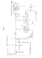
FIG. 9 is a diagram showing the details of a
contactless AC/DC changeover unit 9 and a first example of a
circuit provided for a control power supply. When the drive
apparatus is connected to a commercial AC power source in a
state in which the vibrating-type compressor 1 for a
refrigerator is operated with a battery being used as a power
source, the drive apparatus is operated by use of the control
AC power source without the battery being disconnected.
-
For battery operation, the drive apparatus is designed
to accept a wide range of input voltage, in consideration of
use in cars, trucks, buses, and watercraft, and has
specifications which enable not only operation in a 12 V
system and a 24 V system, but operation over a range of 10 V
to 32 V. For AC operation, the drive apparatus is equipped
with a selected AC/DC converter for, for example, 100 V (110
V) input or 200 V (240 V) input; i.e., an AC/DC converter
having specifications suitable for a region in which the
drive apparatus is used. Although these two power systems
are connected together by means of a diode OR circuit
composed of Schottky diodes, the control systems for these
power systems must be changed over simultaneously with
changeover between the two power systems.
-
When the battery 2 is connected to the drive apparatus,
the voltage from the battery 2 turns on a transistor Trl
shown in FIG. 9, so that the battery voltage is supplied to a
voltage monitor circuit 16. When a commercial AC power
source is connected to the drive apparatus in this state, a
transistor Tr2 (FIG. 9) is turned on by means of voltage from
the AC/DC converter 8 (FIG. 1), and stops the base current of
the transistor Tr1 in order to turn off the transistor Tr1.
Thus, the battery-side power supply is shut off. At the same
time, at the time of AC input, a voltage signal is fed to the
switching control IC 30 of the DC/DC converter control unit
27 (FIG. 2) in order to stop the DC/DC converter 7, whereby
the battery is disconnected from the power system. Therefore,
the diode OR circuit for the power systems does not provide
an OR function in the state in which both the power systems
output power, but provides a contactless switch function.
-
As will be described with reference to FIG. 10, the
voltage monitor circuit 16 detects a voltage of a power
source connected. When the detected voltage is proper, the
voltage monitor circuit 16 outputs a constant voltage (12 V)
and supplies it to the DC/DC converter control unit 27 and
the inverter control unit 7. When the battery voltage or the
output voltage of the AC/DC converter drops to a level lower
than a reference value, the voltage monitor circuit 16
detects such a voltage drop and turns off the output.
-
The output voltage of the voltage monitor circuit 16 is
supplied to the control-use constant voltage generation
circuit 28 via a switch SW for turning on and off the
refrigerator or freezer, a light-emitting diode 47 for
displaying the operation state, and a buzzer circuit 45. In
the conventional apparatus, the power supply line is branched,
and a current limiting resistor is inserted into the branch
path in order to detect a "voltage," thereby displaying the
operation state. However, this conventional scheme lowers
the overall efficiency by an amount corresponding to the
amount of current flowing through the light-emitting diode.
By contrast, in the circuit shown in FIG. 9, since the light-emitting
diode for displaying the on state is inserted
directly into the main current path, the overall efficiency
of the circuit does not decrease.
-
The buzzer circuit 45 detects the temperature in the
vicinity of the condenser of the refrigerator by use of the
illustrated thermistor. When the detected temperature
exceeds a preset temperature, the buzzer circuit 45
automatically shuts off the power supply of the refrigerator
and operates a buzzer 44 via a buzzer driver 43, and
maintains this state until the user turns off the power
switch SW. In particular, in the case of a built-in-type
refrigerator to be fitted into a depressed portion of a wall
of a watercraft or land vehicle, since flow of air is limited
and heat radiation efficiency decreases, failure of the
refrigerator itself must be prevented.
-
The buzzer circuit 45 imparts a relatively large
hysteresis to a threshold value when the buzzer circuit 45
detects the temperature. Further, upon detection of a high
temperature, the buzzer circuit 45 operates the buzzer 44 and
automatically stops the refrigerator in order to prevent
discharge of the battery. The buzzer circuit 45 achieves
this action by turning off a transistor Tr3 and thus stopping
the supply of voltage to the control-use constant voltage
generation circuit 28. Since the electrical power for the
buzzer circuit 45 is supplied from a constant voltage circuit
42 disposed in a stage preceding the transistor Tr3, the
operation of the buzzer continues until the user turns off
the switch SW.
-
The control-use constant voltage generation circuit 28
may be constituted by a three-terminal regulator and operate
so as to generate a constant voltage of 12 V, so long as the
output voltage of the voltage monitor circuit 16 is applied
thereto, and regardless of whether the applied voltage is 12
V or 24 V.
-
FIG. 10 is a diagram showing the details of the voltage
motor circuit 16. The following description is based on the
assumption that either 12 V or 24 V is supplied from the
battery or the AC/DC converter. A transistor Tr4 judges
whether the output of the battery or the AC/DC converter is
12 V or 24 V.. The circuit constants of a circuit including
the transistor Tr4 are determined such that when the input
voltage applied from the battery is greater than 18 V (a
threshold value corresponding to the center value between 12
V and 24 V), a zener diode ZD4 comes into a conductive state
to thereby turn on the transistor Tr4. In other words, the
voltage type of the battery (or the commercial power source)
is judged through the above-described operation.
-
First, a case in which a 12-V battery is connected to
the drive apparatus will be considered. Since the transistor
Tr4 maintains its off state as described above, a voltage
(e.g., 5 V) obtained through proportional division of the
input voltage 12 V at a ratio of R42:(R43+R45) is applied to
a non-inverting terminal of an operational amplifier 54. At
this time, a voltage (e.g., 5 V) obtained through
proportional division of a constant voltage appearing across
a zener diode ZD5 at a ratio of R50:R53 is applied to an
inverting terminal of the operational amplifier 54. However,
whereas the voltage applied to the inverting terminal of the
operational amplifier 54 is maintained constant through the
action of the zener diode ZD5, the voltage applied to the
non-inverting terminal of the operational amplifier 54 varies
in proportion to the battery voltage. Therefore, when the
battery voltage is not greater than 12 V, the voltage applied
to the non-inverting terminal of the operational amplifier 54
is lower than the constant voltage applied to the inverting
terminal thereof, so that the operational amplifier 54 does
not generate an output signal. When the battery voltage
exceeds 12 V, the voltage applied to the non-inverting
terminal of the operational amplifier 54 becomes higher than
the constant voltage applied to the inverting terminal
thereof, so that the operational amplifier 54 generates a
positive output signal.
-
Further, the signal output from the operational
amplifier 54 is fed back to the non-inverting terminal via a
feedback resistor R47. Therefore, the operational amplifier
54 does not enter an off state immediately after the battery
voltage decreases to a level below 12 V in a state in which
the power supply is operated by the battery; i.e., the
operational amplifier 54 generates the output signal properly.
The circuit constants can be set such that the operational
amplifier 54 enters an off state when the battery voltage
becomes equal to or lower than, for example, 11 V, due to
further voltage drop. When the battery voltage exceeds 18 V,
the above-described circuit judges that a 24-V battery is
connected to the drive apparatus as described above. In such
a case, the operational amplifier 54 enters an off state, as
will become apparent from the following description (the case
of the battery voltage being not greater than 24 V).
-
Next, a case in which a 24-V battery is connected to
the drive apparatus will be considered. Since the transistor
Tr4 comes into an on state in this case, a voltage obtained
through proportional division of the input voltage 24 V at a
ratio of R42: (R43+R44·R45/(R44+R45) is applied to the non-inverting
terminal of an operational amplifier 54. At this
time, the same voltage as that applied during use of the 12 V
system is applied to the inverting terminal of the
operational amplifier 54 by the zener diode ZD5. Therefore,
when the voltage which is proportional to the battery voltage
and is applied to the non-inverting terminal is set to a
voltage (e.g., 5 V) which is equal to that in the case of the
above-described 12-V battery being connected, this circuit
operates in the same manner as in the case of the 12 V system.
That is, the circuit can be configured in such a manner that
when the battery voltage exceeds 24 V, the operational
amplifier 54 generates an output, and once the output is
generated, the operational amplifier 54 maintains its on
state unless the battery voltage becomes equal to or lower
than 22 V.
-
When the operational amplifier 54 generates an output,
the output turns on a transistor Tr5 and then turns on a
transistor Tr6, to thereby output the battery voltage applied
to the input terminal to a next stage as an output voltage.
-
As described above, in the assumed case in which a 12-V
or 24-V power source is connected to the drive apparatus, the
voltage type used is judged, and when the voltage becomes
equal to or lower than, for example, 11 V or 22 V, an
anomalous state is judged to have occurred, and the output is
turned off. Otherwise, the battery voltage is judged to be
proper, and the control-use constant voltage generation
circuit 28 outputs a constant voltage of DC 12 V regardless
of the voltage type used. Although the above description has
been made on the assumption that 12-V and 24-V power sources
are selectively connected to the drive apparatus, the drive
apparatus can cope with a larger number of types of batteries
and AC/DC converters through slight change of the circuit,
and even when an arbitrary power source is connected to the
drive circuit, the voltage monitor circuit 16 can detect a
voltage drop corresponding to the power source.
-
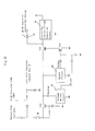
FIG. 11 is a diagram showing the details of the
contactless AC/DC changeover unit 9 and a second example of a
circuit provided for a control power supply. The AC/DC
changeover unit 9 shown in FIG. 11 has basically the same
configuration as that shown in FIG. 9, except that an output
voltage from the transistor Tr2, which enters an on state
upon reception of voltage from the AC/DC converter 8, is used
as a signal which is sent to the DC/DC converter control unit
27 in order to stop the DC/DC converter at the time of AC
input. This configuration reduces the number of components
and consumed current.
-
Further, a shut-off circuit operating when the voltage
monitor circuit 16 or the buzzer circuit 45 senses an
anomalous state, is not provided in the power supply line.
The voltage monitor circuit 16 and the buzzer circuit 45
merely sense the voltage on the power supply line and control
a transistor Tr4 connected to the ground side of the control-use
constant voltage generation circuit 28, via a diode OR
circuit disposed between the voltage monitor circuit 16 and
the buzzer circuit 45 and the transistor Tr4. This
configuration decreases the number of transistors inserted
into the power supply line, so that the lowest operation
voltage for battery use decreases, and the effective range of
power supply voltage for battery input increases. Notably,
as shown in FIG. 11, a shunt resistor maybe connected in
parallel to the light-emitting diode 47 for display purpose.
-
FIG. 12 is a diagram showing the details of the
contactless AC/DC changeover unit 9 and a third example of a
circuit provided for a control power supply. In the circuit
shown in FIG. 12, the output voltage of the AC/DC converter
used for AC input is set to a voltage; e.g., 39 V, which is
outside the range of input battery voltage (10 V to 32 V);
and the output voltage of the AC/DC converter and the battery
voltage are received by a diode OR circuit. Further, a shut-off
circuit operating when the voltage monitor circuit 16 or
the buzzer circuit 45 senses an anomalous state, is not
provided in the power supply line. The voltage monitor
circuit 16 and the buzzer circuit 45 merely sense the voltage
on the power supply line. The voltage monitor circuit 16 and
the buzzer circuit 45 are connected to the transistor Tr4 via
a diode OR circuit. The transistor Tr4 controls the
transistor Tr3 disposed in the power supply line in order to
shut off supply of power in the case of an anomalous state
having occurred. This circuit arrangement simplifies the
circuit configuration.
-
FIG. 13 is a diagram showing the details of the
contactless AC/DC changeover unit 9 and a fourth example of a
circuit provided for a control power supply. The circuit
shown in FIG. 13 incorporates in combination the feature of
the second example shown in FIG. 11 and the feature of the
third example shown in FIG. 12. That is, similar to the
third example, the output voltage of the AC/DC converter used
for AC input is set to a voltage; e.g., 39 V, which is
outside the range of input battery voltage (10 V to 32 V);
and the output voltage of the AC/DC converter and the battery
voltage are received by a diode OR circuit. Further, similar
to the second example, a shut-off circuit operating when the
voltage monitor circuit 16 or the buzzer circuit 45 senses an
anomalous state, is not provided in the power supply line.
The voltage monitor circuit 16 and the buzzer circuit 45
merely sense the voltage on the power supply line and control
a transistor Tr4 connected to the ground side of the control-use
constant voltage generation circuit 28, via a diode OR
circuit disposed between the voltage monitor circuit 16 and
the buzzer circuit 45, and the transistor Tr4.
-
FIG. 16 is a general block diagram showing another
drive apparatus for a vibrating-type compressor to which the
present invention is applied. The drive apparatus shown in
FIG. 16 differs from the drive circuit shown in FIG. 1 in
that the inverter 6 is constituted by a bridge-type inverter
and that the circuit for driving the inverter 6 has a
different configuration. Therefore, descriptions of the same
circuits as those shown in FIG. 1 are omitted.
-
The inverter 6 comprises serially connected first and
second FETs 4 and 5 and serially connected third and fourth
FETs 14 and 15, which form a bridge circuit. The bridge-type
inverter itself is well known. The connection point between
the first and second FETs 4 and 5 is connected to one
terminal of the vibrating-type compressor 1, and the
connection point between the first and second FETs 14 and 15
is connected to the other terminal of the vibrating-type
compressor 1. A resistor R for detecting instantaneous
current flowing through the inverter 6 is serially connected
to the FET 5.
-
The first FET 4 and the fourth FET 15, which form a
pair, are turned on simultaneously, and the second FET 5 and
the third FET 14, which form a pair, are turned on
simultaneously. However, these pairs are controlled such
that the two pairs alternately turn on over a phase period of
120°, as in the case of the first and second FETs which have
been described with reference to FIG. 1.
-
A power circuit for driving a DC fan motor 18 for
cooling the radiator of the refrigerator is connected in
parallel to the inverter 6 and receives power from the same
power source as that for the inverter 6.
-
FIG. 17 is a circuit diagram showing the details of the
drive control circuit 33 which constitutes the inverter
control unit 7 shown in FIG. 16. The drive control circuit
33 shown in FIG. 17 differs from that shown in FIG. 6 in that
the circuit configuration is modified in order to drive the
bridge-type inverter circuit comprising four FETs; i.e., the
first through fourth FETs. Descriptions of portions having
the same configuration as those shown in FIG. 6 are omitted.
As in the circuit shown in FIG. 6, the frequency of pulses
output from the first to fourth FETs of the inverter 6 is
changed in order to change the frequency of AC voltage
applied to the vibrating-type compressor 1. As have been
described with reference to FIG. 6, a pulse signal shown in
section c of FIG. 7 is supplied to FET 4 of the inverter 6.
The pulse signal c is inverted by a driver and is then
applied to the FET 4. The pulse signal c is applied to the
FET 15 via a polarity inverter 12, which inverts the polarity
of the signal. As a result, the signal applied to the FET 15
has the same waveform as that of the signal applied to the
FET 4. Similarly, the pulse signal d shown in FIG. 7 is
applied to the FET 14 via a polarity inverter 13 and a driver.
As a result, the signal applied to the FET 14 has the same
waveform as that of the signal applied to the FET 5.
-
In the above-described manner, the pair including the
first FET 4 and the fourth FET 15 and the pair including the
second FET 5 and the third FET 14 are turned on alternately
such that each FET is in an on state over a 120° phase angle,
as have been described with reference to FIG. 6. Thus, the
vibrating-type compressor 1 is supplied with an AC voltage
having a waveform which includes a 30° dead time, a 120°
positive period, a 60° dead time, a 120° positive period, and
a 30° dead time in each cycle.
-
In the present invention, changeover between the
battery 2 and the commercial AC power source 10; i.e.,
changeover between AC and DC, is effected without use of a
mechanical changeover unit; instead, the battery 2 and the
commercial AC power source 10 are connected by use of a diode
OR circuit. This configuration eliminates mechanical
contacts from the power system to thereby decrease failure
rate; i.e., to improve reliability. Further, since the
conversion of AC → DC → AC performed during AC input is
simpler than the conventionally practiced conversion of AC →
DC → DC → AC, the drive apparatus has improved conversion
efficiency and consumes less power.
-
Further, in the present invention, the FETs disposed in
the upper and lower arms of the inverter are turned on
alternately such that each FET is in an on state over a 100°
to 140° phase angle. Therefore, as compared with 180°
alternating supply of electricity, a wave closer to a
sinusoidal wave can be supplied to the vibrating-type
compressor, whereby the operation efficiency of the
vibrating-type compressor itself is improved. Further, since
the on period is slightly changed on the basis of the
detected ambient temperature of the vibrating-type compressor,
the efficiency can be improved further, and the valve-hitting
phenomena peculiar to vibrating-type compressors can be
prevented.