EP1111752B1 - Instantaneous fault detection circuit method and apparatus - Google Patents
Instantaneous fault detection circuit method and apparatus Download PDFInfo
- Publication number
- EP1111752B1 EP1111752B1 EP00311485A EP00311485A EP1111752B1 EP 1111752 B1 EP1111752 B1 EP 1111752B1 EP 00311485 A EP00311485 A EP 00311485A EP 00311485 A EP00311485 A EP 00311485A EP 1111752 B1 EP1111752 B1 EP 1111752B1
- Authority
- EP
- European Patent Office
- Prior art keywords
- current
- peak
- block
- value
- trip
- Prior art date
- Legal status (The legal status is an assumption and is not a legal conclusion. Google has not performed a legal analysis and makes no representation as to the accuracy of the status listed.)
- Expired - Lifetime
Links
Images


Classifications
-
- H—ELECTRICITY
- H02—GENERATION; CONVERSION OR DISTRIBUTION OF ELECTRIC POWER
- H02H—EMERGENCY PROTECTIVE CIRCUIT ARRANGEMENTS
- H02H1/00—Details of emergency protective circuit arrangements
- H02H1/0092—Details of emergency protective circuit arrangements concerning the data processing means, e.g. expert systems, neural networks
-
- H—ELECTRICITY
- H02—GENERATION; CONVERSION OR DISTRIBUTION OF ELECTRIC POWER
- H02H—EMERGENCY PROTECTIVE CIRCUIT ARRANGEMENTS
- H02H7/00—Emergency protective circuit arrangements specially adapted for specific types of electric machines or apparatus or for sectionalised protection of cable or line systems, and effecting automatic switching in the event of an undesired change from normal working conditions
- H02H7/26—Sectionalised protection of cable or line systems, e.g. for disconnecting a section on which a short-circuit, earth fault, or arc discharge has occured
- H02H7/30—Staggered disconnection
-
- H—ELECTRICITY
- H02—GENERATION; CONVERSION OR DISTRIBUTION OF ELECTRIC POWER
- H02H—EMERGENCY PROTECTIVE CIRCUIT ARRANGEMENTS
- H02H1/00—Details of emergency protective circuit arrangements
- H02H1/04—Arrangements for preventing response to transient abnormal conditions, e.g. to lightning or to short duration over voltage or oscillations; Damping the influence of dc component by short circuits in ac networks
Definitions
- the present invention relates generally to electronic trip units for circuit breakers and more particularly to electronic trip units providing instantaneous fault detection for circuit breakers.
- Electronic trip units are well known. Electronic trip units typically comprise voltage and current sensors that provide analog signals indicative of the power line signals. The analog signals are converted by an A/D (analog/digital) converter to digital signals which are processed by a microcontroller.
- the trip unit further includes RAM (random access memory), ROM (read only memory) and EEPROM (electronic erasable programmable read only memory) all of which interface with the microcontroller.
- the ROM includes trip unit application code, e.g., main functionality firmware, including initializing parameters, and boot code.
- the EEPROM includes operational parameters for the application code.
- trip units are required to meet certain standards, e.g., UL/ANSI/IEC, which define trip time curves specifying under what conditions a trip must occur, i.e., short time, long time, instantaneous, or ground fault, all of which are well known. These standards also specify a short time delay from the instant power is applied to when a trip unit must be ready to trip.
- UL/ANSI/IEC e.g., UL/ANSI/IEC
- US 5,237,511 relates to a distribution automation smart remote terminal unit for use in electrical power distribution networks.
- the present invention is being directed to the instantaneous trip condition.
- Various electronic circuits analog electronics
- customized integrated circuits application specific integrated circuit (ASIC)
- ASIC application specific integrated circuit
- Conventional low voltage electronic trip units have used a simple comparison to detect instantaneous trip conditions. This type of circuit compares the instantaneous current with a fixed threshold, and upon attainment of that threshold the electronic trip unit will trigger the breaker to open. Due to well-known load transients such as motor inrush, this approach almost always overprotects and results in nuisance tripping.
- the first half-cycle can theoretically appear to reach two times the motor inrush current, or sixteen times the normal operational current. Nonetheless, various industry standards and code requirements determine instantaneous set points at which level the breaker is required to trip.
- the actual peak current that occurs is a function of the closing angle and impedance (X/R) of the line/load combination.
- Asymmetry also may occur in fault transients. For example a fault of ten times the rated current for a circuit breaker can theoretically appear to be twenty times the rated current for a particular half cycle.
- Light impedance (X/R) again limits this theoretical maximum to 1.7 to 1.9 times the steady state current.
- X/R again limits this theoretical maximum to 1.7 to 1.9 times the steady state current.
- Peak-to-peak current comparisons are known in the field of protective relays for protection of high voltage loads.
- protection relays sold by General Electric Company as model numbers DFP-100, DFP-200 and F30 employ algorithms using peak-to-peak current values.
- protective relays are generally standalone or rack mounted devices installed physically separate from the circuit breaker. Furthermore, by virtue of being installed separately, they are generally not self-powered and are energized prior to the breaker or load being energized. Consequently, the protective relay begins sampling prior to breaker closing and properly records zero current as the level prior to current flow. With electronic trip units, this generally does not occur, because when the breaker is closed, current generally flows simultaneously to the load and to the electronic trip unit.
- the present invention provides a method and apparatus for protecting the load from instantaneous, or bolted, current overloads based on peak-to-peak current values for this simultaneous current flow while minimizing the existing problem nuisance tripping due to load transients.
- the above-discussed and other drawbacks and deficiencies of the prior art are overcome or alleviated by the method and apparatus of the present invention.
- the algorithmic approach provides protection to electrical systems by detecting true electrical spikes, and further by accurately determining when current overloads are present.
- the electronic trip unit of the present invention is particularly well suited for use in a selective breaker system.
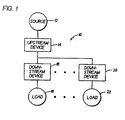
- the selective system may comprise, for example, a current source, an upstream circuit breaker and trip unit, a plurality of downstream circuit breakers and trip units and corresponding loads.
- the downstream circuit breakers and trip units are rated to meet the demands of the corresponding loads and are said to trip at lower peaks as compared to the upstream circuit breakers and trip units.
- the circuit breaker trip unit includes a current transformer providing an input current to a rectifying means, whereupon said input currents are detected for a certain polarity and converted to a low level voltage signal for processing.
- the low-level voltage signals are then processed via a signal processor where the signals are acted upon by a series of algorithms.
- the processing means comprises an analog-to-digital converter and a microprocessor. If certain conditions of the algorithms are met, communications with an actuator by, for example, an output signal will energize a trip solenoid, which will cause the contacts of the breaker device to open.
- the algorithmic arrangement is a set of algorithms, which can be briefly described by the following two-step sequences:
- Selective system 10 comprises a source 12, an upstream device (circuit breaker and trip unit) 14, a downstream device (circuit breaker and trip unit) 16, and at least one corresponding load 18. Any number of additional downstream devices (circuit breakers and trip units) 20, with corresponding loads 22 may be included.
- the downstream devices 16, 20 are rated to meet the demands of the corresponding loads 18, 22 and are set to trip as described hereinafter.
- the upstream device 14 is rated to meet the demands of the system and is also set to trip as described hereinafter.
- Trip unit 30 comprises a polarity sensor 32, which provides analog signals indicative of polarity status of power line signals on a signal line 34, and a current sensor 36, which provides analog signals indicative of a current measurement of power line signals on a signal line 38.
- the analog signals on lines 34 and 38 are manipulated by an analog/digital (A/D) converter 40, which converts these analog signals to digital signals.
- A/D analog/digital
- the digital signals are presented over a bus 42 to a signal processor or microcontroller 44, such as one commercially available from Hitachi (i.e., HA/300 family of microcontrollers).
- Microcontroller 44 communicates with a random access memory (RAM) 46, a read only memory (ROM) 48 and an electronic erasable programmable read only memory (EEPROM) 50 over a control bus 52.
- RAM random access memory
- ROM read only memory
- EEPROM electronic erasable programmable read only memory
- EEPROM 50 is preferably non-volatile so that system information and programming will not be lost during a power interruption or outage.
- An output control device 54 receives control signals from microcontroller 44 over control bus 52. Control device 54 controls a trip module 56 via a line 58.
- a power supply 62 which is powered by the service electricity, provides appropriate operational power over a line 64 to the components of trip unit 30.
- ROM 48 includes trip unit application code or algorithms, which are mainly functionality firmware including initializing parameters and boot code.
- the application code includes code for the algorithmic approach of the present invention.
- EEPROM 50 includes operational parameter code, such as code for setting the number of peaks for a trip or the sensitivity of the trip unit. These parameters will typically be stored in the trip unit at the factory and are selected to meet customers' requirements, but may be configured based on the customer needs as is well known in the art.
- FIG. 3 depicts algorithmic procedure 70, which is repeated for each current sample.
- the frequency of the current samples is a function of the speed of the current sensors, the speed of the A/D converter, the processing capabilities of the microcontroller and other operational variations.
- a current sample I (obtained from current sensors 36 and preferably processed by A/D converter) is presented in step 72 to the microcontroller 44 and related software encompassed by ROM 48, RAM 46 and EEPROM 50.
- ROM 48 obtained from current sensors 36 and preferably processed by A/D converter
- RMS root mean square
- the unit will not trip after a single current value exceeding A. Rather to distinguish between a true fault current and a transient glitch occurs, multiple consecutive current samples are compared to A.
- the number of samples required to trip, n is predetermined such that n is a function of the sampling rate for the trip unit and should be selected to span approximately 1-2 milliseconds.
- III is not greater than A
- the algorithm proceeds to block 78 of the flow chart, where n(tc) is reset to zero.
- III is greater than A less than n times, and the second algorithm has not caused a trip, the spike is due to a momentary fault. Comparison of consecutive samples rather that a single sample aids in the prevention of nuisance tripping due to transient glitches.
- the peak-to-peak current (referenced as pk-pk in Figure 3 ) is compared to the RMS instantaneous fault current set point, I SP .
- the detection of two peaks accurately takes into effect the potential reduction of a fault current.
- the second algorithm determines the sum of an earlier stored or preceding peak [peak (-2)] and the average value of the most recent peak [peak (-1)] and the absolute value of the current of the present sample (
- the sample processed at a given point in time is represented by I.
- the previous sample processed is represented by I(-1).
- the values for the most recent peak current value peak(-1) and the preceding peak current value peak(-2) have yet to be determined and/or stored in memory.
- flags are correlated with the existence of a stored value for the peak. These flags are represented herein in the negative, where a flag is set if a certain peak value is non-existent, as no_peak(-1) and no_peak(-2).
- a polarity flag is used to determine whether the half-cycle has changed, i.e., the polarity of the present sample I differs from the polarity of the previous sample I(-1). The polarity flag remains unset (cleared) until a peak(-1) has been determined. Furthermore, I(-1) is yet to be determined at an initial startup condition.
- Block 92 determines whether no_peak(-2) has been set.
- no_peak(-2) is set.
- the query of block 92 is answered affirmatively, whereby the algorithm proceeds to block 100 where the process for storing peak(-1) and peak(-2) with the subsequent samples is commenced.
- Block 100 determines whether the polarity flag has been set. For an initial sample, the polarity flag will not be set, as there has not been a peak(-1) determination, and the algorithm will flow to block 102. The polarity flag will set when a peak(-1) is ascertained and stored, as described further herein, and it will return to the unset state when a polarity change is detected by polarity sensor 32. If it is determined by block 100 that a polarity flag has been set, the algorithm will proceed to block 120. For the algorithmic processing of an initial sample, block 102 determines whether the absolute value of the current of the present sample
- the flow chart proceeds through the first algorithm 74 as described previously. If the trip count does not exceed n, or if
- the algorithmic scheme differs from the initial sample, as there is a value for
- the polarities of the present sample and previous sample are compared. If the polarity of I is different from the polarity of the previous sample I(-1), the polarity flag will be cleared at block 122 (however, under startup conditions this step is redundant as the polarity flag has not been set) and the flow will proceed to block 124. At block 124, the value of I(-1) is set to the present sample and the previous I(-1) is cleared. If, at block 120, the polarity of I and I(-1) are the same, the flow will proceed directly to block 124 and the new I(-1) will be set to the present I.
- the flow will proceed to determine peak(-1), beginning at block 104.
- no_peak(-1) flag is set, indicating a lack of a value for peak(-1).
- the flow will proceed to block 106, where no_peak(-1) flag is cleared (as the determination of a value for peak(-1) will occur in the next step).
- the polarity flag is set for the polarity of the current at the present half-cycle. For subsequent samples, no peak measurements take place until the polarity changes and the polarity flag is cleared (blocks 120 and 122).
- block 120 (which flows from block 100, block 102, and block 114) determines whether the polarity of the present sample
- no_peak(-1) flag is cleared, the polarity flag is set (as peak(-1) is set), peak(-2) has not been determined, and the no_peak(-2) flag remains set.
- the next sample proceeds from block 72 through the first algorithm, where upon the breaker will trip if n(TC) exceeds n. If not, the flow proceeds to block 92.
- the no_peak(-2) flag is still set as peak(-2) has yet to be determined thus the flow proceeds to block 100 where it is determined that the polarity flag has been set.
- Block 102 (containing equation 3) is bypassed, and the flow proceeds to block 120 where it is determined whether the polarity has changed from the previous sample I(-1) to the present sample I. Another [peak(-1)] cannot be determined until the phase current polarity changes. When this occurs, the polarity flag is cleared (block 122), I(-1) is set to the value of the present I (block 124) and the flow awaits the next sample (block 126).
- a new sample I is processed through the first algorithm. If the breaker has not tripped (i.e.
- is not greater than twice the RMS instantaneous fault set point, or the trip count is not greater than n), the flow proceeds to block 92 of the second algorithm. Again if the query of block 92 is answered affirmatively (as is the case when a peak(-2) has yet to be set), then the flow proceeds to block 100. At block 100, the polarity flag has been cleared, thus the flow proceeds to block 102 where the comparison of equation 3 is effectuated.
- the algorithmic flow proceeds from block 102 to block 120 and the phase current polarity of the present sample I is compared with the polarity of the previous sample I(-1) (block 120), as previously described. If
- no_peak(-2) flag is set (as peak(-2) has not been set) thus block 108 is answered affirmatively and the flow proceeds to block 110 whereupon the no_peak(-2) flag is cleared (since peak(-2) will be set). Proceeding from block 110 to block 112, peak(-2) is set to equal the present peak(-1). A new peak(-1) is set to equal the absolute value of the current of the previous sample and the polarity flag is set at block 114.
- the present phase current polarity is compared to that of the previous sample as described above. No peak measurement will occur until the phase current polarity changes and the polarity flag is cleared at block 122. Proceeding from block 122 (if the phase current polarity changed from the previous sample) or block 120 (if the phase current polarity did not change), the previous current sample I(-1) is reset to the present current sample I (block 124) and the algorithm is set to await the next sample (block 126).
- the polarity changes and a peak(-2) has been set the conditions are as follows:
- both peaks have been set and the second algorithm is ready to calculate the peak-to-peak current based upon peak(-1), peak(-2) and
- the peak-to-peak current may then be compared with the instantaneous set point or a factor thereof.
- the breaker will trip as indicated at block 200. This is appropriate, as it would indicate that the present current I is high enough that, when averaged with the previous peak ([
- the downstream breaker rated at 250 ampere will trip during the first half-cycle as the absolute value of the current (greater than 6,000 ampere RMS) exceeds two times the set point (i.e., 5,000 ampere). This is accomplished by the first algorithm depicted generally at 74. However note that the upstream breaker rated 400 ampere will not trip, as the absolute value of the current does not exceed two times the set point (i.e., 8,000 ampere). Note that the past electronic instantaneous circuit protection approaches would have caused both breakers to open immediately, which would create a nuisance trip for other breakers or loads fed from the 400 ampere bus.
Description
- The present invention relates generally to electronic trip units for circuit breakers and more particularly to electronic trip units providing instantaneous fault detection for circuit breakers.
- Electronic trip units are well known. Electronic trip units typically comprise voltage and current sensors that provide analog signals indicative of the power line signals. The analog signals are converted by an A/D (analog/digital) converter to digital signals which are processed by a microcontroller. The trip unit further includes RAM (random access memory), ROM (read only memory) and EEPROM (electronic erasable programmable read only memory) all of which interface with the microcontroller. The ROM includes trip unit application code, e.g., main functionality firmware, including initializing parameters, and boot code. The EEPROM includes operational parameters for the application code.
- These trip units are required to meet certain standards, e.g., UL/ANSI/IEC, which define trip time curves specifying under what conditions a trip must occur, i.e., short time, long time, instantaneous, or ground fault, all of which are well known. These standards also specify a short time delay from the instant power is applied to when a trip unit must be ready to trip.
-
US 5,237,511 relates to a distribution automation smart remote terminal unit for use in electrical power distribution networks. - The present invention is being directed to the instantaneous trip condition. Various electronic circuits (analog electronics) and customized integrated circuits (application specific integrated circuit (ASIC)) have been employed to perform instantaneous protection. Conventional low voltage electronic trip units have used a simple comparison to detect instantaneous trip conditions. This type of circuit compares the instantaneous current with a fixed threshold, and upon attainment of that threshold the electronic trip unit will trigger the breaker to open. Due to well-known load transients such as motor inrush, this approach almost always overprotects and results in nuisance tripping.
- Further, because of a transient phenomenon known as asymmetry, the first half-cycle can theoretically appear to reach two times the motor inrush current, or sixteen times the normal operational current. Nonetheless, various industry standards and code requirements determine instantaneous set points at which level the breaker is required to trip.
- Under conditions of asymmetry, the actual peak current that occurs is a function of the closing angle and impedance (X/R) of the line/load combination. Asymmetry also may occur in fault transients. For example a fault of ten times the rated current for a circuit breaker can theoretically appear to be twenty times the rated current for a particular half cycle. Light impedance (X/R) again limits this theoretical maximum to 1.7 to 1.9 times the steady state current. As such, using the conventional electronic comparison approach, in a feeder breaker system, both breakers will trip rather than only the breaker closest to the load. This problem may be alleviated by employing a peak-to-peak current comparison.
- Peak-to-peak current comparisons are known in the field of protective relays for protection of high voltage loads. For example, protection relays sold by General Electric Company as model numbers DFP-100, DFP-200 and F30 employ algorithms using peak-to-peak current values. However, such protective relays are generally standalone or rack mounted devices installed physically separate from the circuit breaker. Furthermore, by virtue of being installed separately, they are generally not self-powered and are energized prior to the breaker or load being energized. Consequently, the protective relay begins sampling prior to breaker closing and properly records zero current as the level prior to current flow. With electronic trip units, this generally does not occur, because when the breaker is closed, current generally flows simultaneously to the load and to the electronic trip unit. The present invention provides a method and apparatus for protecting the load from instantaneous, or bolted, current overloads based on peak-to-peak current values for this simultaneous current flow while minimizing the existing problem nuisance tripping due to load transients.
- The above-discussed and other drawbacks and deficiencies of the prior art are overcome or alleviated by the method and apparatus of the present invention. The algorithmic approach provides protection to electrical systems by detecting true electrical spikes, and further by accurately determining when current overloads are present.
- The electronic trip unit of the present invention is particularly well suited for use in a selective breaker system. The selective system may comprise, for example, a current source, an upstream circuit breaker and trip unit, a plurality of downstream circuit breakers and trip units and corresponding loads. The downstream circuit breakers and trip units are rated to meet the demands of the corresponding loads and are said to trip at lower peaks as compared to the upstream circuit breakers and trip units. The circuit breaker trip unit includes a current transformer providing an input current to a rectifying means, whereupon said input currents are detected for a certain polarity and converted to a low level voltage signal for processing. The low-level voltage signals are then processed via a signal processor where the signals are acted upon by a series of algorithms. In one embodiment, the processing means comprises an analog-to-digital converter and a microprocessor. If certain conditions of the algorithms are met, communications with an actuator by, for example, an output signal will energize a trip solenoid, which will cause the contacts of the breaker device to open.
- In a preferred embodiment, the algorithmic arrangement is a set of algorithms, which can be briefly described by the following two-step sequences:
- Step 1: Compare the absolute value of the current signal with a value equal to two multiplied by the square root of two multiplied by the instantaneous set point; if the current value is greater for N consecutive samples, trip the circuit breaker; if not, proceed to
Step 2; - Step 2: Obtain the values of the peak-to-peak current and compare to a value equal to two multiplied by the square root of two multiplied by the RMS instantaneous set point; if the peak-to-peak current is greater, trip the circuit breaker; if not, return to
Step 1. - An embodiment of the invention will now be described , by way of example, with reference to the accompanying drawings, in which:
-
Figure 1 is a schematic block diagram of a selective circuit trip system; -
Figure 2 is a schematic block diagram of an electronic trip unit; and -
Figure 3 is a flow diagram of the algorithmic procedure of the present invention. - Referring to
Figure 1 , a selective system is generally shown at 10.Selective system 10 comprises asource 12, an upstream device (circuit breaker and trip unit) 14, a downstream device (circuit breaker and trip unit) 16, and at least onecorresponding load 18. Any number of additional downstream devices (circuit breakers and trip units) 20, withcorresponding loads 22 may be included. Thedownstream devices corresponding loads upstream device 14 is rated to meet the demands of the system and is also set to trip as described hereinafter. - Referring now to
Figure 2 , a general schematic of a trip unit is shown at 30. The dual algorithm approach described hereinafter is preferably applied independently upon each phase current protected by the circuit breaker.Trip unit 30 comprises a polarity sensor 32, which provides analog signals indicative of polarity status of power line signals on asignal line 34, and acurrent sensor 36, which provides analog signals indicative of a current measurement of power line signals on asignal line 38. The analog signals onlines converter 40, which converts these analog signals to digital signals. The digital signals are presented over abus 42 to a signal processor ormicrocontroller 44, such as one commercially available from Hitachi (i.e., HA/300 family of microcontrollers).Microcontroller 44 communicates with a random access memory (RAM) 46, a read only memory (ROM) 48 and an electronic erasable programmable read only memory (EEPROM) 50 over a control bus 52. The analog/digital converter 40,ROM 48,RAM 46 and EEPROM 50, or any combination thereof, may be internal tomicrocontroller 44, as is well known in the art. EEPROM 50 is preferably non-volatile so that system information and programming will not be lost during a power interruption or outage. Anoutput control device 54 receives control signals frommicrocontroller 44 over control bus 52.Control device 54 controls atrip module 56 via aline 58. A power supply 62, which is powered by the service electricity, provides appropriate operational power over aline 64 to the components oftrip unit 30. Alternatively, polarity sensor 32 andcurrent sensor 36 are powered directly by the power lines.ROM 48 includes trip unit application code or algorithms, which are mainly functionality firmware including initializing parameters and boot code. The application code includes code for the algorithmic approach of the present invention.EEPROM 50 includes operational parameter code, such as code for setting the number of peaks for a trip or the sensitivity of the trip unit. These parameters will typically be stored in the trip unit at the factory and are selected to meet customers' requirements, but may be configured based on the customer needs as is well known in the art. - The algorithmic approach of the present invention will now be described in more detail with reference to
Figure 3. Figure 3 depictsalgorithmic procedure 70, which is repeated for each current sample. The frequency of the current samples is a function of the speed of the current sensors, the speed of the A/D converter, the processing capabilities of the microcontroller and other operational variations. A current sample I (obtained fromcurrent sensors 36 and preferably processed by A/D converter) is presented in step 72 to themicrocontroller 44 and related software encompassed byROM 48,RAM 46 andEEPROM 50. In the first algorithm, generally denoted by reference numeral 74, bolted faults are detected quickly. At block 76, the first algorithm effectuates a comparison between the absolute value of the current (III) and a threshold value A determined by the following equation:

- Preferably, to prevent nuisance trips caused by momentary faults or other transient current glitches, the unit will not trip after a single current value exceeding A. Rather to distinguish between a true fault current and a transient glitch occurs, multiple consecutive current samples are compared to A. The number of samples required to trip, n, is predetermined such that n is a function of the sampling rate for the trip unit and should be selected to span approximately 1-2 milliseconds.
- If III is greater than A, the algorithmic flow proceeds from block 76 to block 80, where the value of the total consecutive trip counts [n(tc)] is increased by one. The
next block 82 compares n(tc) with n. If n is exceeded, thenmicrocontroller 44 will direct a trip signal viaoutput 54 to tripmodule 56 to open the circuit breaker, indicated atblock 200 offlow char 70. When n is not exceeded by n(tc), the process continues as shown toward the second algorithm generally denoted in the flow chart asalgorithm 90, discussed further herein. - If III is not greater than A, the algorithm proceeds to block 78 of the flow chart, where n(tc) is reset to zero. Generally, if III is greater than A less than n times, and the second algorithm has not caused a trip, the spike is due to a momentary fault. Comparison of consecutive samples rather that a single sample aids in the prevention of nuisance tripping due to transient glitches.
- Proceeding to the second algorithm, depicted by
reference numeral 90, the peak-to-peak current (referenced as pk-pk inFigure 3 ) is compared to the RMS instantaneous fault current set point, ISP. The detection of two peaks accurately takes into effect the potential reduction of a fault current. In a subsequent half cycle due to, for example, opening of a downstream circuit breaker or the passing of the asymmetry phenomenon. Generally, the second algorithm determines the sum of an earlier stored or preceding peak [peak (-2)] and the average value of the most recent peak [peak (-1)] and the absolute value of the current of the present sample (|I|). That sum is compared to a value equal to twice the RMS value of the instantaneous set point (2 ISP 2½), and if the sum is greater, a fault condition will accurately be detected and the breaker will trip. - Certain variables for the second algorithm are required to determine the two peaks required. The sample processed at a given point in time is represented by I. The previous sample processed is represented by I(-1). At a startup condition, either upon initial operation of the system, after a trip caused by the first or second algorithm or after a manual resetting of the system, the values for the most recent peak current value peak(-1) and the preceding peak current value peak(-2) have yet to be determined and/or stored in memory. Thus, flags are correlated with the existence of a stored value for the peak. These flags are represented herein in the negative, where a flag is set if a certain peak value is non-existent, as no_peak(-1) and no_peak(-2). If no_peak(-1) has been set, then a peak(-1) must be determined and stored. Similarly, if no_peak(-2) has been set, then a peak(-2) must be determined and stored. Additionally, as described in more detail herein, a polarity flag is used to determine whether the half-cycle has changed, i.e., the polarity of the present sample I differs from the polarity of the previous sample I(-1). The polarity flag remains unset (cleared) until a peak(-1) has been determined. Furthermore, I(-1) is yet to be determined at an initial startup condition.
- Therefore, for a first sample at a startup condition, the following variable values exist:
- I = present current value;
- I(-1) = (to be determined);
- no_peak(-1) = set;
- no_peak(-2) = set;
- peak(-1) = (to be determined);
- peak(-2) = (to be determined); and
- polarity flag = cleared.
- Block 92 determines whether no_peak(-2) has been set. At a startup condition continuing from a negative response in block 82 (i.e., no trip because the absolute value of the current has exceeded twice the RMS instantaneous fault set point a single time rather than n times) or block 78 (i.e., no trip because the absolute value of the current has not exceeded twice the RMS instantaneous fault set point, block 76, and the trip count n(tc) remains zero at block 78), no_peak(-2) is set. The query of block 92 is answered affirmatively, whereby the algorithm proceeds to block 100 where the process for storing peak(-1) and peak(-2) with the subsequent samples is commenced.
-
Block 100 determines whether the polarity flag has been set. For an initial sample, the polarity flag will not be set, as there has not been a peak(-1) determination, and the algorithm will flow to block 102. The polarity flag will set when a peak(-1) is ascertained and stored, as described further herein, and it will return to the unset state when a polarity change is detected by polarity sensor 32. If it is determined byblock 100 that a polarity flag has been set, the algorithm will proceed to block 120. For the algorithmic processing of an initial sample, block 102 determines whether the absolute value of the current of the present sample |I| is greater than the absolute value of the current of the previous sample |I(-1)|:
- For a first sample where I(-1) does not exist, |I| will be presumably greater than |I(-1)| and the algorithm will continue from block 102 to block 120. At
block 120, a determination is made as to whether the polarity of I is different from the polarity of I(-1). However with an initial sample I, I(-1) does not exist thus the negative response to the query ofblock 120 occurs. Continuing from a negative response inblock 120, the algorithm proceeds to block 124 where the previous sample I(-1) is set to equal the current value of the present sample I. Atblock 126, the flow returns to step 72 whereupon processing of a new sample I commences. In processing the immediately subsequent sample, the no_peak(-1) and no_peak(-2) flags are set, the polarity flag is clear, and |(-1) has been set (the value of I for the previous sample). As with all samples, the flow chart proceeds through the first algorithm 74 as described previously. If the trip count does not exceed n, or if |I| is less than A, the flow returns to the second algorithm. With the second sample, the query of block 92 is again answered affirmatively and the query ofblock 100 is again answered negatively. - Proceeding to block 102, the algorithmic scheme differs from the initial sample, as there is a value for |(-1). If the absolute value of the current of the present sample |I| exceeds the absolute value of the current of the previous sample, |I(-1)|, the flow proceeds to block 120. At
block 120, the polarities of the present sample and previous sample are compared. If the polarity of I is different from the polarity of the previous sample I(-1), the polarity flag will be cleared at block 122 (however, under startup conditions this step is redundant as the polarity flag has not been set) and the flow will proceed to block 124. Atblock 124, the value of I(-1) is set to the present sample and the previous I(-1) is cleared. If, atblock 120, the polarity of I and I(-1) are the same, the flow will proceed directly to block 124 and the new I(-1) will be set to the present I. - If at block 102 the absolute value of the current for the sample is less than or equal to the absolute value of the current for the previous sample, the flow will proceed to determine peak(-1), beginning at
block 104. Atblock 104, it is determined whether a peak(-1) has been set. In the algorithmic flow depicted, this is accomplished by the no_peak(-1) flag, which indicates the existence of a value for peak(-1). At initialization, no_peak(-1) flag is set, indicating a lack of a value for peak(-1). Thus, the first time a subsequent sample has a lower current than the previous sample, the flow will proceed to block 106, where no_peak(-1) flag is cleared (as the determination of a value for peak(-1) will occur in the next step). Proceeding fromblock 106 to block 114, a peak(-1) is set, whereby peak(-1) = |I(-1)|. Further, the polarity flag is set for the polarity of the current at the present half-cycle. For subsequent samples, no peak measurements take place until the polarity changes and the polarity flag is cleared (blocks 120 and 122). - The next step, block 120 (which flows from
block 100, block 102, and block 114) determines whether the polarity of the present sample |I| is different from the polarity of the previous sample I(-1). If so, the algorithmic flow proceeds to block 122, where the polarity flag is cleared and then the present current value I replaces the previous |(-1) (block 124). When the polarity of I is the same as the polarity of I(-1), the algorithmic flow proceeds directly to block 124 where the present I substitutes the previous I(-1). - Thus, at this point, in the algorithmic flow peak(-1) has been determined, no_peak(-1) flag is cleared, the polarity flag is set (as peak(-1) is set), peak(-2) has not been determined, and the no_peak(-2) flag remains set. The next sample proceeds from block 72 through the first algorithm, where upon the breaker will trip if n(TC) exceeds n. If not, the flow proceeds to block 92. As previously mentioned, the no_peak(-2) flag is still set as peak(-2) has yet to be determined thus the flow proceeds to block 100 where it is determined that the polarity flag has been set. Block 102 (containing equation 3) is bypassed, and the flow proceeds to block 120 where it is determined whether the polarity has changed from the previous sample I(-1) to the present sample I. Another [peak(-1)] cannot be determined until the phase current polarity changes. When this occurs, the polarity flag is cleared (block 122), I(-1) is set to the value of the present I (block 124) and the flow awaits the next sample (block 126).
- Thus, when the polarity changes and a peak(-2) has yet to be set, the conditions are as follows:
- I = present current value
- I (-1) = (determined);
- no_peak(-1) = cleared
- no_peak(-2) = set;
- peak(-1) = (determined);
- peak(-2) = (to be determined); and
- polarity flag = cleared.
- Proceeding from
block 126 to block 72, a new sample I is processed through the first algorithm. If the breaker has not tripped (i.e. |I| is not greater than twice the RMS instantaneous fault set point, or the trip count is not greater than n), the flow proceeds to block 92 of the second algorithm. Again if the query of block 92 is answered affirmatively (as is the case when a peak(-2) has yet to be set), then the flow proceeds to block 100. Atblock 100, the polarity flag has been cleared, thus the flow proceeds to block 102 where the comparison of equation 3 is effectuated. If |I| is greater than |I(-1)|, the algorithmic flow proceeds from block 102 to block 120 and the phase current polarity of the present sample I is compared with the polarity of the previous sample I(-1) (block 120), as previously described. If |I| is less than or equal to |I(-1)|, the algorithmic flow proceeds to set peak(-2) and reset peak(-1). Thus, proceeding from block 102 to block 104, a determination is made as to whether the no_peak(-1) flag is set. At this point, the no_peak(-1) flag is cleared (as peak(-1) is set) thus block 104 is answered negatively, and the flow proceeds to block 108. At block 108, a determination is made as to whether the no_peak(-2) flag is set. At this point, the no_peak(-2) flag is set (as peak(-2) has not been set) thus block 108 is answered affirmatively and the flow proceeds to block 110 whereupon the no_peak(-2) flag is cleared (since peak(-2) will be set). Proceeding fromblock 110 to block 112, peak(-2) is set to equal the present peak(-1). A new peak(-1) is set to equal the absolute value of the current of the previous sample and the polarity flag is set atblock 114. - Proceeding from
block 114 to block 120, the present phase current polarity is compared to that of the previous sample as described above. No peak measurement will occur until the phase current polarity changes and the polarity flag is cleared atblock 122. Proceeding from block 122 (if the phase current polarity changed from the previous sample) or block 120 (if the phase current polarity did not change), the previous current sample I(-1) is reset to the present current sample I (block 124) and the algorithm is set to await the next sample (block 126). Thus, when the polarity changes and a peak(-2) has been set, the conditions are as follows: - I = present current value;
- I(-1) = determined;
- no_peak(-1) flag=cleared;
- no_peak(-2) flag=cleared;
- peak(-1) = (determined);
- peak(-2) = (determined); and
- polarity flag=cleared.
- At this stage, both peaks have been set and the second algorithm is ready to calculate the peak-to-peak current based upon peak(-1), peak(-2) and |I|. The peak-to-peak current may then be compared with the instantaneous set point or a factor thereof.
- Proceeding again from
block 126 to block 72, a new current sample |I| is processed. If the breaker is not tripped due to the exceeded trip count limits atblock 82 of the first algorithm, sample I is processed in the second algorithm starting at block 92. A negative response to the query in block 92 (i.e. no_peak(-2) flag is cleared) directs the flow to block 94, where the peak-to-peak current may be determined by the following equation:
- This calculation is repeated for every current sample where peak(-1) and a peak(-2) both exist, or block 92 is answered negatively. The value obtained, pk-pk, is compared at block 96 to two times the RMS instantaneous set point of the protected device or breaker as follows:

- If pk-pk exceeds two times the RMS instantaneous set point, the breaker will trip as indicated at
block 200. This is appropriate, as it would indicate that the present current I is high enough that, when averaged with the previous peak ([|I| + peak(-2)]/2) and that average summed with the most recent peak [peak(-1)], two times the RMS instantaneous set point is exceeded. - When pk-pk is less than or equal to two times the RMS instantaneous set point, there will be no trip and the second algorithm will proceed to block 100. If a new peak(-1) has been determined in the present half-cycle, the polarity flag will be set and an affirmative response to the query in
block 100 will direct the algorithmic flow to block 120. No new peaks will be stored until a polarity change is detected (or, upon the occurrence of a new half-cycle) atblock 120 and the polarity is cleared atblock 122. For subsequent samples within a new half-cycle, i.e., the polarity flag is cleared, a negative response to the query ofblock 100 will result, directing the algorithmic flow to check for new prospective peak values to store, as described above. - It is understood by one skilled in the art that the algorithmic flow relayed herein may be modified by known techniques. For example, algorithms and or subroutines may be appended to compensate for any errors that occur in this detection method due to the sampling error. Similarly, an analog circuit approach may substitute the algorithm for the digitally sampled system described herein. Such an analog circuit, for example, may use multiple or linked peak detecting circuits that would implement the same algorithms.
- To illustrate the operation of the algorithmic approach described herein, examples will be described and the processing steps delineated. Consider the case of a 250 ampere breaker fed from a 400 ampere bus with both breakers set at an instantaneous fault of ten times the rated current. If this system is operating with no fault for a period of time equivalent to at least two half-cycles, peak(-1) and peak(-2) values will be set and equations 4 and 5 of blocks 94 and 96 respectively will be calculated. If, for example, during the first half-cycle, a 4,100 ampere fault occurs with a 1.5 asymmetry, then the system will "see" a fault in excess of 6,000 ampere. If such fault continues for n samples spanning, for example, 1 millisecond (i.e. not a mere "transient glitch"), the downstream breaker rated at 250 ampere will trip during the first half-cycle as the absolute value of the current (greater than 6,000 ampere RMS) exceeds two times the set point (i.e., 5,000 ampere). This is accomplished by the first algorithm depicted generally at 74. However note that the upstream breaker rated 400 ampere will not trip, as the absolute value of the current does not exceed two times the set point (i.e., 8,000 ampere). Note that the past electronic instantaneous circuit protection approaches would have caused both breakers to open immediately, which would create a nuisance trip for other breakers or loads fed from the 400 ampere bus.
- If the 4,100 ampere fault is not limited, during the next half-cycle another peak will be stored as peak(-1) and the old peak(-1) will be stored as peak(-2). In the processing of the immediately subsequent sample I, if the fault is still present (or a value of I is high enough to inflate the pk-pk value above two times the RMS setting, or 8,000 ampere for the upstream breakers), the pk-pk value in equation 4 (block 94) will exceed two times the RMS instantaneous fault set point for the upstream 400 ampere breaker.
- After the first half-cycle, the asymmetry phenomenon will disappear. Thus, peak(-2) (the first peak seen) will equal 6,150 ampere and peak(-1) and absolute value of |I| will equal 4,100 ampere. Performing the calculation,

- If instead a 4,100 ampere fault occurs without asymmetry (or, a 1.0 asymmetry value) on the first half-cycle, neither the downstream 250 ampere breaker nor the upstream 400 ampere breaker will trip after the first algorithm. However, after two half-cycles, if the fault is still present, [peak(-1)], [peak(-2)] and |I| will equal approximately 4,100 ampere, and pk-pk will equal 8,200 ampere thus even without asymmetry, both breakers will correctly trip a 4,100 ampere fault.
Claims (5)
- A method of protection in an electronic trip unit (30), comprising:sensing an electrical signal of a current flow to provide present current values of said current flow (72);performing an instantaneous current comparison between the sensed present current value and a first current threshold (74) and generating a trip signal when an absolute value of the sensed current is equal to or greater than the first current threshold (74) for N consecutive samples of current;characterized by performing a peak-to-peak current comparison between a multiple peak sum and a second current threshold (90) and generating a trip signal when said peak sum exceeds said second current threshold (90).
- The method as in claim 1, said peak-to-peak current comparison (90) further comprising:storing a most recent peak current value (114);storing a preceding peak current value (112);calculating a peak sum of said most recent peak current value and an average of said current value of the present current signal and said preceding peak current value (94);comparing said peak sum to a second threshold current value (96); andgenerating a trip signal when said peak sum exceeds said second current threshold (200).
- An electronic trip unit (30) comprising:a current sensor (36) operable to provide a current value indicative of a present current (72);a microcontroller (44) operable to perform an instantaneous current comparison between the sensed present current value (72) and a first current threshold (74) and to generate a trip signal when an absolute value of the sensed current is equal to or greater than the first current threshold (74) for N consecutive samples of current, characterized by being operable to perform a peak-to-peak current comparison between a multiple peak sum and a second current threshold (90) and to generate a trip signal when said peak sum exceeds said second current threshold (90).
- The electronic trip unit (30) of claim 3, further wherein:a count (n(tc)) is commenced upon generation of said signal (80);said count being incremented if the absolute value of a subsequent current value exceeds said first current threshold (80);a trip signal being generated when said count reaches a predetermined count limit (200); andsaid count being cleared if the absolute value of said subsequent current value does not exceed said first current threshold (76-no).
- The electronic trip unit (30) of claim 3, wherein said microcontroller (44) is operable to perform said peak-to-peak current comparison (90) by:storing a most recent peak current value (114);storing a preceding peak current value (112);calculating a peak sum of said most recent peak current value, and an average of said current value of the present current signal and said preceding peak current value (94);comparing said peak sum to a second threshold current value (96); and generating a trip signal when said peak sum exceeds said second current threshold (200).
Applications Claiming Priority (2)
| Application Number | Priority Date | Filing Date | Title |
|---|---|---|---|
| US09/467,744 US6545849B1 (en) | 1999-12-20 | 1999-12-20 | Instantaneous fault detection circuit method and apparatus |
| US467744 | 1999-12-20 |
Publications (3)
| Publication Number | Publication Date |
|---|---|
| EP1111752A2 EP1111752A2 (en) | 2001-06-27 |
| EP1111752A3 EP1111752A3 (en) | 2005-08-24 |
| EP1111752B1 true EP1111752B1 (en) | 2010-06-23 |
Family
ID=23856993
Family Applications (1)
| Application Number | Title | Priority Date | Filing Date |
|---|---|---|---|
| EP00311485A Expired - Lifetime EP1111752B1 (en) | 1999-12-20 | 2000-12-20 | Instantaneous fault detection circuit method and apparatus |
Country Status (4)
| Country | Link |
|---|---|
| US (2) | US6545849B1 (en) |
| EP (1) | EP1111752B1 (en) |
| CN (1) | CN1331287C (en) |
| DE (1) | DE60044575D1 (en) |
Families Citing this family (15)
| Publication number | Priority date | Publication date | Assignee | Title |
|---|---|---|---|---|
| DE10343350A1 (en) * | 2003-09-12 | 2005-04-21 | Siemens Ag | Method of controlling an electronic overcurrent release for low voltage circuit breakers |
| EP1884787A1 (en) * | 2006-07-10 | 2008-02-06 | S. THIIM ApS | A current sensor for measuring electric current in a conductor and a short circuit indicator system comprising such a sensor |
| US20080151444A1 (en) * | 2006-12-20 | 2008-06-26 | John D Upton | Method and apparatus for protection against current overloads |
| US8072723B2 (en) * | 2007-06-19 | 2011-12-06 | General Electric Company | Resettable MEMS micro-switch array based on current limiting apparatus |
| FI120565B (en) * | 2007-12-20 | 2009-11-30 | Abb Oy | Method and apparatus for detecting grounding |
| WO2009101463A1 (en) * | 2008-02-15 | 2009-08-20 | Abb Technology Ag | A standalone self-supplied numeric controlled relay |
| US8520352B2 (en) * | 2008-02-25 | 2013-08-27 | Xylem Ip Holdings Llc | Multiple-channel active sensing and switching device |
| CN103383908B (en) * | 2012-05-04 | 2015-08-19 | 上海安科瑞电气股份有限公司 | A kind of checkout gear of on-off state of multi-loop miniature circuit breaker |
| US9488714B2 (en) | 2013-03-15 | 2016-11-08 | General Electric Company | Methods and systems for continuous calibration of circuit breaker trip units and metering devices |
| US9659721B1 (en) * | 2014-05-06 | 2017-05-23 | Google Inc. | Circuit breakers with integrated safety, control, monitoring, and protection features |
| US9966206B1 (en) | 2015-05-06 | 2018-05-08 | Google Llc | Circuit breakers with integrated safety, control, monitoring, and protection features |
| US10673226B2 (en) * | 2017-02-22 | 2020-06-02 | Abb Schweiz Ag | Power distribution systems and methods of operating power distribution systems with a communication network |
| US10797479B2 (en) | 2017-02-22 | 2020-10-06 | Abb Schweiz Ag | Power distribution systems and methods of performing ground fault detection in power distribution systems with a communication network |
| CN110556801B (en) * | 2019-09-11 | 2021-07-20 | 云南电力技术有限责任公司 | Power distribution automation FTU locking protection method |
| CN111557739B (en) * | 2020-01-14 | 2023-05-02 | 杭州法博激光科技有限公司 | Computer storage medium suitable for soft mirror auxiliary device |
Family Cites Families (13)
| Publication number | Priority date | Publication date | Assignee | Title |
|---|---|---|---|---|
| US4150411A (en) * | 1977-12-15 | 1979-04-17 | General Electric Company | Ground fault circuit interrupter utilizing a single transformer |
| US4377836A (en) * | 1980-04-15 | 1983-03-22 | Westinghouse Electric Corp. | Circuit interrupter with solid state digital trip unit and positive power-up feature |
| US4597025A (en) * | 1980-07-10 | 1986-06-24 | Eaton Corporation | Minimum size, integral, A.C. overload current sensing, remote power controller |
| US4443854A (en) * | 1981-06-08 | 1984-04-17 | Electric Power Research Institute, Inc. | Current sensor responsive to symmetrical and asymmetrical currents and current limiting protector utilizing same |
| FR2578090B1 (en) * | 1985-02-25 | 1989-12-01 | Merlin Gerin | CIRCUIT BREAKER WITH DIGITAL STATIC TRIGGER WITH REVERSE TIME TRIGGERING FUNCTION |
| DE3638935A1 (en) * | 1985-11-22 | 1987-05-27 | Gen Electric | SIGNAL ADJUSTMENT CIRCUIT FOR ELECTRONIC RELEASE SWITCHES |
| US5136459A (en) * | 1989-03-13 | 1992-08-04 | Electric Power Research Institute, Inc. | High speed current limiting system responsive to symmetrical & asymmetrical currents |
| US5237511A (en) * | 1990-10-29 | 1993-08-17 | Westronic, Inc. | Distribution automation smart remote terminal unit |
| US5224011A (en) * | 1991-04-19 | 1993-06-29 | Gas Research Institute | Multifunction protective relay system |
| FR2762156B1 (en) * | 1997-04-15 | 1999-06-11 | Schneider Electric Sa | SELECTIVE ELECTRONIC TRIGGER, CIRCUIT BREAKER CONTAINING SUCH A TRIGGER AND SELECTIVE TRIGGERING PROCESS |
| US5963406A (en) * | 1997-12-19 | 1999-10-05 | Leviton Manufacturing Co., Inc. | Arc fault detector with circuit interrupter |
| US5943204A (en) * | 1998-01-12 | 1999-08-24 | Eaton Coroporation | Electronic trip unit with dedicated override current sensor |
| US6545949B1 (en) * | 2001-09-21 | 2003-04-08 | Her Majesty The Queen In Right Of Canada, As Represented By The Minister Of National Defence | Axial drive resonant pipe projector (ADRPP) |
-
1999
- 1999-12-20 US US09/467,744 patent/US6545849B1/en not_active Expired - Lifetime
-
2000
- 2000-12-20 EP EP00311485A patent/EP1111752B1/en not_active Expired - Lifetime
- 2000-12-20 CN CNB001370715A patent/CN1331287C/en not_active Expired - Fee Related
- 2000-12-20 DE DE60044575T patent/DE60044575D1/en not_active Expired - Lifetime
-
2003
- 2003-01-20 US US10/348,061 patent/US7016174B2/en not_active Expired - Fee Related
Also Published As
| Publication number | Publication date |
|---|---|
| US6545849B1 (en) | 2003-04-08 |
| DE60044575D1 (en) | 2010-08-05 |
| EP1111752A2 (en) | 2001-06-27 |
| US7016174B2 (en) | 2006-03-21 |
| CN1331287C (en) | 2007-08-08 |
| CN1306329A (en) | 2001-08-01 |
| US20030107860A1 (en) | 2003-06-12 |
| EP1111752A3 (en) | 2005-08-24 |
Similar Documents
| Publication | Publication Date | Title |
|---|---|---|
| EP1111752B1 (en) | Instantaneous fault detection circuit method and apparatus | |
| Maier | Protection of squirrel-cage induction motor utilizing instantaneous power and phase information | |
| EP2115844B1 (en) | Arc fault circuit interrupter and method of parallel arc fault detection | |
| US5164876A (en) | Static trip device comprising an earth protection desensitization system | |
| EP1279213B1 (en) | Sensitive ground fault detection system for use in compensated electric power distribution networks | |
| US6434715B1 (en) | Method of detecting systemic fault conditions in an intelligent electronic device | |
| AU749406B2 (en) | Electrical switching apparatus employing interlocks for first and second trip functions | |
| EP0686851B1 (en) | Digitally controlled circuit interrupter with improved automatic selection of sampling interval for 50 Hz and 60 Hz power systems | |
| US5768079A (en) | Adaptive ground and phase fault detection for a power distribution system | |
| US5172329A (en) | Microprocessor-based digital protective relay for power transformers | |
| EP2176933B1 (en) | Arc fault circuit interrupter and method of detecting and interrupting a resistive series arc of a power circuit | |
| US20030086224A1 (en) | Circuit breaker for detecting an excessive voltage and tripping responsive thereto | |
| AU2001257462A1 (en) | Sensitive ground fault detection system for use in compensated electric power distribution networks | |
| JPS63107412A (en) | Tripper of breaker | |
| CA1320561C (en) | Loss-of-potential supervision for a distance relay | |
| JP2004080839A (en) | Ground direction relay and ground direction relay device | |
| EP0674376B1 (en) | Overcurrent trip unit with separately adjustable neutral protection | |
| US20030128035A1 (en) | Fault locator and selectivity sensor | |
| KR960002325B1 (en) | Digital type over-current/under-current relay method of the switch-board in electronic type | |
| KR960002324B1 (en) | Digital type overvoltage/undervoltage relay apparatus of the switch-board in electronic type | |
| Apostolov | Improving power quality by optimizing the protection of distribution systems | |
| JPH05168142A (en) | Ground fault detector and detection protector at different points on distribution line | |
| JP2000278856A (en) | Protective relay device | |
| JPH03195329A (en) | Unnotified power interruption detector |
Legal Events
| Date | Code | Title | Description |
|---|---|---|---|
| PUAI | Public reference made under article 153(3) epc to a published international application that has entered the european phase |
Free format text: ORIGINAL CODE: 0009012 |
|
| AK | Designated contracting states |
Kind code of ref document: A2 Designated state(s): AT BE CH CY DE DK ES FI FR GB GR IE IT LI LU MC NL PT SE TR |
|
| AX | Request for extension of the european patent |
Free format text: AL;LT;LV;MK;RO;SI |
|
| PUAL | Search report despatched |
Free format text: ORIGINAL CODE: 0009013 |
|
| AK | Designated contracting states |
Kind code of ref document: A3 Designated state(s): AT BE CH CY DE DK ES FI FR GB GR IE IT LI LU MC NL PT SE TR |
|
| AX | Request for extension of the european patent |
Extension state: AL LT LV MK RO SI |
|
| 17P | Request for examination filed |
Effective date: 20060224 |
|
| AKX | Designation fees paid |
Designated state(s): DE FR |
|
| 17Q | First examination report despatched |
Effective date: 20061002 |
|
| GRAP | Despatch of communication of intention to grant a patent |
Free format text: ORIGINAL CODE: EPIDOSNIGR1 |
|
| GRAS | Grant fee paid |
Free format text: ORIGINAL CODE: EPIDOSNIGR3 |
|
| GRAA | (expected) grant |
Free format text: ORIGINAL CODE: 0009210 |
|
| AK | Designated contracting states |
Kind code of ref document: B1 Designated state(s): DE FR |
|
| REF | Corresponds to: |
Ref document number: 60044575 Country of ref document: DE Date of ref document: 20100805 Kind code of ref document: P |
|
| PLBE | No opposition filed within time limit |
Free format text: ORIGINAL CODE: 0009261 |
|
| STAA | Information on the status of an ep patent application or granted ep patent |
Free format text: STATUS: NO OPPOSITION FILED WITHIN TIME LIMIT |
|
| 26N | No opposition filed |
Effective date: 20110324 |
|
| REG | Reference to a national code |
Ref country code: DE Ref legal event code: R097 Ref document number: 60044575 Country of ref document: DE Effective date: 20110323 |
|
| PGFP | Annual fee paid to national office [announced via postgrant information from national office to epo] |
Ref country code: DE Payment date: 20131230 Year of fee payment: 14 |
|
| PGFP | Annual fee paid to national office [announced via postgrant information from national office to epo] |
Ref country code: FR Payment date: 20131217 Year of fee payment: 14 |
|
| REG | Reference to a national code |
Ref country code: DE Ref legal event code: R119 Ref document number: 60044575 Country of ref document: DE |
|
| REG | Reference to a national code |
Ref country code: FR Ref legal event code: ST Effective date: 20150831 |
|
| PG25 | Lapsed in a contracting state [announced via postgrant information from national office to epo] |
Ref country code: DE Free format text: LAPSE BECAUSE OF NON-PAYMENT OF DUE FEES Effective date: 20150701 |
|
| PG25 | Lapsed in a contracting state [announced via postgrant information from national office to epo] |
Ref country code: FR Free format text: LAPSE BECAUSE OF NON-PAYMENT OF DUE FEES Effective date: 20141231 |