EP1111711A2 - Stucture of rod antenna guide port in cellular telephone - Google Patents
Stucture of rod antenna guide port in cellular telephone Download PDFInfo
- Publication number
- EP1111711A2 EP1111711A2 EP00307255A EP00307255A EP1111711A2 EP 1111711 A2 EP1111711 A2 EP 1111711A2 EP 00307255 A EP00307255 A EP 00307255A EP 00307255 A EP00307255 A EP 00307255A EP 1111711 A2 EP1111711 A2 EP 1111711A2
- Authority
- EP
- European Patent Office
- Prior art keywords
- rod antenna
- sleeve
- slit
- inclination
- pulled out
- Prior art date
- Legal status (The legal status is an assumption and is not a legal conclusion. Google has not performed a legal analysis and makes no representation as to the accuracy of the status listed.)
- Withdrawn
Links
Images



Classifications
-
- H—ELECTRICITY
- H01—ELECTRIC ELEMENTS
- H01Q—ANTENNAS, i.e. RADIO AERIALS
- H01Q1/00—Details of, or arrangements associated with, antennas
- H01Q1/12—Supports; Mounting means
- H01Q1/22—Supports; Mounting means by structural association with other equipment or articles
- H01Q1/24—Supports; Mounting means by structural association with other equipment or articles with receiving set
-
- H—ELECTRICITY
- H01—ELECTRIC ELEMENTS
- H01Q—ANTENNAS, i.e. RADIO AERIALS
- H01Q1/00—Details of, or arrangements associated with, antennas
- H01Q1/08—Means for collapsing antennas or parts thereof
- H01Q1/084—Pivotable antennas
-
- H—ELECTRICITY
- H01—ELECTRIC ELEMENTS
- H01Q—ANTENNAS, i.e. RADIO AERIALS
- H01Q1/00—Details of, or arrangements associated with, antennas
- H01Q1/12—Supports; Mounting means
- H01Q1/22—Supports; Mounting means by structural association with other equipment or articles
- H01Q1/24—Supports; Mounting means by structural association with other equipment or articles with receiving set
- H01Q1/241—Supports; Mounting means by structural association with other equipment or articles with receiving set used in mobile communications, e.g. GSM
- H01Q1/242—Supports; Mounting means by structural association with other equipment or articles with receiving set used in mobile communications, e.g. GSM specially adapted for hand-held use
- H01Q1/243—Supports; Mounting means by structural association with other equipment or articles with receiving set used in mobile communications, e.g. GSM specially adapted for hand-held use with built-in antennas
- H01Q1/244—Supports; Mounting means by structural association with other equipment or articles with receiving set used in mobile communications, e.g. GSM specially adapted for hand-held use with built-in antennas extendable from a housing along a given path
Definitions
- This invention relates to a structure of a rod antenna guide port for allowing a rod antenna of a cellular telephone to be pulled out therethrough with an inclination in a direction away from the side of its user's head.
- a lower end portion of an attachment threaded sleeve, which defines the rod antenna guide port 2 is split to form a split spring sleeve 23 having a plurality of split spring elements 24 and the rod antenna 1 in the inclination position is held by the split spring sleeve 23.
- an eccentric hole (precision circular hole) S2 for offsetting the lower end portion of the antenna 1 to one side and a precision circular hole S1 for forming the split spring sleeve 24 are arranged with a shift in location, i.e., the two precision circular holes S1, S2 are eccentrically arranged, so that the offset amount is set by this eccentric amount W1.
- the split spring sleeve 21 having a plurality of split spring elements 22 is formed by splitting the lower end portion of the attachment threaded sleeve which defines most part of the rod antenna guide port 2
- the entire attachment threaded sleeve including the split spring sleeve 21 must be made of beryllium copper which is suited as a spring material but which is very expensive. This gives rise to a problem in that the cost is increased.
- the entire attachment threaded sleeve made of beryllium copper must be cut and in addition, the beryllium copper having a high degree of hardness and difficult to be cut must be cut. This can further increase the cost.
- the structure in which the amount of offset is set based on the amounts of eccentricity W1 of the two perfect circular holes S1, S2 has such problems that if the amount of eccentricity W1 of the perfect circular hole S2 with respect to the perfect circular hole S1, it becomes difficult to receive the rod antenna in its vertical posture and therefore, a sufficient amount of eccentricity W1 is difficult to obtain, thus making it difficult to obtain a sufficient inclination angle of the rod antenna.
- the present invention has been accomplished in view of the above situation.
- an object of the present invention to provide, in order to amicably solve the various problems involved in the related art, a structure of a rod antenna guide port in which a rod antenna received in a cellular telephone can be pulled out with an inclination.
- a structure of a rod antenna guide port in a cellular telephone comprising a rod antenna guide port for allowing a rod antenna in a cellular telephone to be pulled out therethrough with an inclination, the guide port including an upper and a lower sleeve hole for allowing the rod antenna to be inserted therein, the lower sleeve hole serving as means for pressing, when the rod antenna is pulled out, one side surface of a lower end portion of the rod antenna so that the rod antenna is offset to one side, thereby enabling to pull out the rod antenna with an inclination through the upper sleeve hole, wherein the upper sleeve hole includes a slit sleeve composed of a plurality of slit elements annularly arranged, a split spring sleeve being externally fitted to the slit sleeve so that the slit sleeve can be expanded and contracted in a radial direction, the slit elements of the slit
- each of the slit elements composing the slip spring sleeve is provided on an intermediate portion of an inner peripheral surface thereof with a contact projection projecting inwardly, and the contact projection is provided on an upper portion thereof with an upper guide hole comprised of an inclination surface expanded(dilated) in a pulling out direction of the rod antenna and on a lower portion thereof with a lower guide hole comprised of an inclination surface expanded (or dilated) in a receiving direction of the rod antenna, such that when the rod antenna is pulled out with an inclination, the antenna lower portion is brought into abutment with the inclination surfaces of the upper and lower guide holes.
- the split elements may be separated from each other.
- the lower sleeve hole is comprised of an enlarged diameter arcuate sleeve portion and a reduced diameter arcuate sleeve portion connected together, and when the rod antenna is pulled out, a connecting angular portion between the enlarged diameter arcuate sleeve hole portion and the reduced diameter arcuate sleeve hole portion press one side surface of a lower portion of the rod antenna so that the rod antenna lower portion is allowed to escape into the enlarged diameter arcuate sleeve hole portion and offset to one side, and when the rod antenna is received in the cellular telephone, an upper end portion of the rod antenna is received into the reduced diameter arcuate sleeve hole portion.
- the present invention relates to a structure of a rod antenna guide port for allowing a rod antenna 1 in a cellular telephone to be pulled out with an inclination.
- the rod antenna 1 received in the cellular telephone is provided at an upper end thereof with an enlarged diameter antenna head la in which a coil is received and at a lower end thereof with an enlarged diameter stopper 1b which is expanded annularly.
- the rod antenna 1 is provided immediately under the antenna head 1a at the upper end thereof with an upper contact rod portion 1c made of electrically conductive metal and immediately above the stopper 1b at the lower end thereof with a lower contact rod portion 1d made of electrically conductive metal.
- the upper and lower rod portions 1c, 1d are composed of a metal sleeve which is externally inserted on and compression bonded to the upper and lower end portions of the rod antenna 1.
- the lower contact rod portion 1d and the stopper 1b form an enlarged diameter portion, as later described.
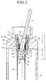
- the antenna guide port 2 includes an upper sleeve hole 3 and a lower sleeve hole 4 which allow the rod antenna 2 1 to be inserted therein.
- the lower sleeve hole 4 forms a means for pressing and offsetting one side surface of the lower end portion of the rod antenna 1 to one side when the rod antenna 1 is pulled out. Due to the offsetting function of the lower sleeve hole 4, the rod antenna 1 is inclined when it is pulled out through the lower sleeve hole 4.
- the rod antenna guide port 2 is defined by an inner sleeve 10 (corresponding to the attachment threaded sleeve 4 in the related art) and an outer sleeve 11 (corresponding to the attachment nut 2) which are both attached to a forming wall of an exterior housing 9 of the cellular telephone.
- Both the inner and outer sleeves 10, 11 are entirely integrally formed from electrically conductive metal. In the present invention, it is not necessary to form them from a panel such as beryllium copper or the like. In one embodiment of the present invention, they are formed from a casting such as an aluminum casting, a zinc casting or the like.
- the outer sleeve 11 is provided at an upper half section thereof with an attachment sleeve portion 12 which is embedded in the forming wall of the exterior housing 9 of the cellular telephone and with a female thread 21 for threadingly engaging the inner sleeve 10 with an inner peripheral surface of the sleeve hole of the attachment sleeve portion 12.
- the outer sleeve 11 is provided at a lower half section thereof with a rod antenna offsetting sleeve portion 13 connected to a lower end of the attachment sleeve portion 12 and projecting inward of the exterior housing 9 from the inner surface of the forming wall of the exterior housing 9.
- the lower sleeve hole 4 is defined by the offsetting sleeve portion 13.
- An upper end of an antenna receiving tube 18 is externally inserted to a lower end of the rod antenna offsetting sleeve portion 13 such that the antenna receiving tube 18 vertically extends within the exterior housing 9.
- the lower sleeve hole 4 includes an enlarged diameter arcuate sleeve hole portion S3 and a reduced diameter arcuate sleeve hole portion S3'.
- One pair of connected angular portions P of both the enlarged and reduced diameter arcuate hole portions S3, S3' define an offset means for pressing, when the rod antenna 1 is pulled out with an inclination, one side surface of the enlarged diameter portion (stopper 1b) of the lower end of the rod antenna 1 so as to be escaped into the enlarged diameter arcuate sleeve hole portion S3.
- Reference numeric symbol W2 denotes an amount of eccentricity of the enlarged diameter arcuate sleeve hole portion S3.
- the enlarged diameter arcuate sleeve hole portion S3 is a circular arc about O1, which is larger than a semi-circular arc.
- the reduced diameter arcuate sleeve hole portion S3' is a circular arc about O2, which is smaller than a semi-circular arc.
- the pair of angular portions P serving as the offset means is formed on a connecting point between the large circular arc and the small circular arc.
- the inner sleeve 10 as shown in FIGS. 1 to 3(A) and 3(B), is provided at an sleeve portion outer peripheral surface of an upper half section thereof with a male thread 22 for threading engagement within the outer sleeve 11 and at the upper end with a flange 14 for setting the depth of threading engagement.
- the sleeve hole of the inner sleeve 10 defines the upper sleeve hole 3.
- the upper end side of the upper sleeve hole 3 is formed into a tapered hole 15 which is expanded (or dilated) outward.
- a slit sleeve 6 and a slit spring sleeve 17 having the under-mentioned construction are mounted at the lower end of the tapered hole 15, i.e., within the upper sleeve hole 3. That is, the split sleeve 6 and the split spring sleeve 17 are mounted within the sleeve portion of the lower half section of the inner sleeve 10.
- the split sleeve 6 and the split spring sleeve 17 are mounted within the sleeve hole portion immediately under the flange 14.
- the split sleeve 6 and the split spring sleeve 17 are mounted within the sleeve hole of the sleeve portion on which the male thread 22 is formed.
- the split spring sleeve 17 is formed by forming a spring material, such as beryllium copper or the like, into a sleeve-like configuration and then forming a split 17a therein in an axial direction.
- a spring material such as beryllium copper or the like
- the split sleeve 6 has such a constitution that it is given to have resiliency by the split spring sleeve 17. Owing to this structure feature, it is not necessarily formed from a spring material and actually, it is formed from a casing such as an aluminum casting, a zinc casting or the like.
- the split sleeve 6 is formed by arranging a plurality of arcuate split elements 7 in an annular form.
- the split spring sleeve 17 is externally fitted to the split sleeve 6 so that the split sleeve 6 can be expanded (or dilated) in a diametrical direction against the resiliency of the split spring sleeve 17 and contracted in accordance with the resiliency.
- the respective arcuate split elements 7 are separated from one another through the split groove 5, to thereby form the split sleeve 6.
- each of the arcuate split elements 7 are connected to another arcuate split element 7 which is adjacent thereto at one end of the split groove 5 such that the split sleeve 6 can be expanded (or dilated) and contracted in the diametrical direction about the connecting portion.
- the split spring sleeve 17 is externally fitted to each of the exemplified split sleeves 6 so that the expanding/contracting resiliency of the arcuate split elements 7 is given to thereto.
- the split sleeve 17 is formed by bending an electrically conductive metal strip formed from a spring material into a square sleeve shape with a single split groove 17a left open and forming an arc-like projecting curvilinear portion 17a at each corner portion of an outer peripheral surface thereof such that the split spring sleeve 17 can resiliently be displaced (expanded or contracted) following the expansion or contraction of the split sleeve 6.
- the split spring sleeve 17 is internally fitted to a lower end sleeve hole of the inner sleeve 10 and the respective projecting curvilinear corner portions 17b are resiliently abutted with an inner wall surface of the lower end sleeve hole of the inner sleeve 10.
- a space t for allowing expansion of the four sides of the split spring sleeve 17 and the split sleeve 6 is formed between adjacent two sides of the four sides of the spring sleeve 17.
- the projecting curvilinear corner portion 17b serves to offer a favorable electrical connection between each arcuate split element 7 and the inner sleeve 10.
- each of the arcuate split elements 7 forming the split sleeve 6 is provided at an intermediate portion of an inner peripheral surface thereof with a contact projection projecting inward of the sleeve hole.
- Each arcuate split element 7 is further provided at an upper portion of the contact projection 8 with an upper guide hole 19 composed of an inclination surface 19' for dilating the rod antenna 1 in the pullout direction and at a lower end portion thereof with a lower guide hole 20 composed of an inclination surface 20' for dilating the rod antenna 1 in the receiving direction.
- the rod antenna 1 pulled out from the inside of the exterior housing 9 of the cellular telephone 1 and offset to one side is inclined and held in the inclination position.
- the arcuate split elements 7 of the split sleeve 6 are pressed with the rod antenna 1 pulled out of the cellular telephone so that the arcuate split elements 7 are dilated against the resiliency of the split spring sleeve 17, and the lower portion of the rod antenna 1 is pressed against the inner walls of the arcuate split elements 7 (i.e., the inclination surfaces 19', 20'of the guide holes 19, 20 by the resilient restoring force of the elements 7 so that the rod antenna 1 is assuredly pulled out with an inclination.
- the inclination surfaces 19', 20' forming the upper guide hole 19 and the lower guide hole 20, respectively, are formed at an inclination angle ⁇ in harmony with an outer surface of the lower end enlarged diameter portion (lower contact rod portion 1d) of the rod antenna 1 which has been pulled out with an inclination and the attitude of inclination of the pulled-out rod antenna 1 is held at an inclination angle ⁇ stably.
- the contact projection 8 is disposed in an annular form extending in a circumferential direction along the inner surfaces of the arcuate split elements 7.
- the diameter R1 of an inscribed circle, which is defined by the contact projection 8 is set smaller than the diameters of the lower end enlarged diameter portion and the upper end portion (the lower contact rod portion 1d or the stopper 1b and the upper contact rod portion 1c) of the rod antenna 1, i.e., the diameter R2 of the enlarged diameter portion.
- the contact projection 8 is resiliently press-contacted with the outer peripheral surface of the intermediate section having a reduced diameter of the rod antenna 1 through co-action between the split sleeve 6 and the split spring sleeve 17, so that the rod antenna 1 is received and held in the cellular telephone with no play.
- the inner sleeve 10 is threadingly engaged with the inner wall of the sleeve hole of the outer sleeve 11, which is embedded for attachment in the forming wall of the exterior housing 9 of the cellular telephone, thereby the rod antenna guide port 2 is formed.
- the inclination surfaces 20' of the arcuate split elements 7 of the split sleeve 6 are abutted with the side surface of the lower end portion of the rod antenna 1 in the offsetting direction and the inclination surfaces 19' of the arcuate split elements 7 are abutted with the other side surface which is opposite to the inclining direction of the rod antenna 1. While dilating the arcuate split elements 7 against the resiliency of the split spring sleeve 17, the rod antenna 1 is inclined and held in the inclination position by reaction thereof.
- the antenna inclining means composed of the split sleeve 6 mounted within the upper sleeve hole 3 and the lower sleeve hole 4 having the offsetting function, the rod antenna is correctly and smoothly pulled out with an inclination and assuredly held in the inclination position after the antenna 1 is pulled out.
- the first half semi-circular portion of the rod antenna 1 is received in the reduced diameter arcuate sleeve hole portion S3' and the second (remaining) half semi-circular portion of the rod antenna 1 is received in the enlarged diameter arcuate sleeve portion S3.
- the rod antenna 1 is fully received in the cellular telephone.
- the contact projection 8 formed on each of the arcuate split elements 7 of the split sleeve 6 is abutted with the outer peripheral surface of the rod antenna 1 in an annular form.
- the antenna inclining means composed of the split sleeve 6 mounted in the upper sleeve hole 3 and the lower sleeve hole 4 having the offsetting function, the rod antenna 1 is correctly and smoothly vertically received in the cellular telephone.
- a sufficient inclination angle can be obtained at the time of pulling out the rod antenna and the antenna can desirably be held in the inclination position after the antenna is pulled out. This serves to restrain the electromagnetic disturbance to a human body during the used of a cellular telephone.
- the split sleeve can be formed from an casting or the like which is inexpensive compared with an expensive cutting article of a spring material.
- a proper resiliency can be given to such obtained split sleeve by a split spring sleeve which is separately formed from a specific spring material.
- the resilient force can easily be set and the adjustment of a resilient force can be made easily so that the rod antenna can be pulled out with a reduced load and the rod antenna can be pulled out with an inclination and properly held in the inclination position by the resilient force.
Landscapes
- Engineering & Computer Science (AREA)
- Computer Networks & Wireless Communication (AREA)
- Support Of Aerials (AREA)
- Details Of Aerials (AREA)
Abstract
Description
Claims (4)
- A structure of a rod antenna guide port in a cellular telephone comprising a rod antenna guide port for allowing a rod antenna in a cellular telephone to be pulled out therethrough with an inclination, said guide port including an upper and a lower sleeve hole for allowing the rod antenna to be inserted therein, said lower sleeve hole serving as means for pressing, when the rod antenna is pulled out, one side surface of a lower end portion of the rod antenna so that the rod antenna is offset to one side, thereby enabling to pull out the rod antenna with an inclination through said upper sleeve hole, wherein said upper sleeve hole includes a slit sleeve composed of a plurality of slit elements annularly arranged, a split spring sleeve being externally fitted to said slit sleeve so that said slit sleeve can be expanded and contracted in a radial direction, said slit elements of said slit sleeve being pressed by the rod antenna pulled out with an inclination so that said slit elements are expanded (or dilated ) against a resilient force of said slit spring sleeve, a lower portion of the rod antenna being pressed against an inner wall of each of said slit elements by a restoring force of said expanded (or dilated) slit elements, so that the rod antenna is assuredly pulled out with an inclination.
- A structure of a rod antenna guide port in a cellular telephone according to claim 1, wherein each of said slit elements composing said slip spring sleeve is provided on an intermediate portion of an inner peripheral surface thereof with a contact projection projecting inwardly, and said contact projection is provided on an upper portion thereof with an upper guide hole comprised of an inclination surface expanded (or dilated) in a pulling out direction of the rod antenna and on a lower portion thereof with a lower guide hole comprised of an inclination surface expanded (or dilated) in a receiving direction of the rod antenna, such that when the rod antenna is pulled out with an inclination, said antenna lower portion is brought into abutment with the inclination surfaces of said upper and lower guide holes.
- A structure of a rod antenna guide port in a cellular telephone according to claim 1 or 2, wherein said split elements are separated from each other.
- A structure of a rod antenna guide port in a cellular telephone according to claim 1, wherein said lower sleeve hole is comprised of an enlarged diameter arcuate sleeve portion and a reduced diameter arcuate sleeve portion connected together, and when the rod antenna is pulled out, a connecting angular portion between said enlarged diameter arcuate sleeve hole portion and said reduced diameter arcuate sleeve hole portion press one side surface of a lower portion of the rod antenna so that the rod antenna lower portion is allowed to escape into said enlarged diameter arcuate sleeve hole portion and offset to one side, and when the rod antenna is received in the cellular telephone, an upper end portion of the rod antenna is received into said reduced diameter arcuate sleeve hole portion.
Applications Claiming Priority (2)
| Application Number | Priority Date | Filing Date | Title |
|---|---|---|---|
| JP36408099A JP3280008B2 (en) | 1999-12-22 | 1999-12-22 | Structure of rod antenna guide opening in mobile phone |
| JP36408099 | 1999-12-22 |
Publications (2)
| Publication Number | Publication Date |
|---|---|
| EP1111711A2 true EP1111711A2 (en) | 2001-06-27 |
| EP1111711A3 EP1111711A3 (en) | 2002-09-18 |
Family
ID=18480929
Family Applications (1)
| Application Number | Title | Priority Date | Filing Date |
|---|---|---|---|
| EP00307255A Withdrawn EP1111711A3 (en) | 1999-12-22 | 2000-08-23 | Stucture of rod antenna guide port in cellular telephone |
Country Status (4)
| Country | Link |
|---|---|
| US (1) | US6615055B1 (en) |
| EP (1) | EP1111711A3 (en) |
| JP (1) | JP3280008B2 (en) |
| KR (1) | KR100530214B1 (en) |
Families Citing this family (6)
| Publication number | Priority date | Publication date | Assignee | Title |
|---|---|---|---|---|
| JP3437821B2 (en) | 2000-06-15 | 2003-08-18 | 日新パーツ株式会社 | Structure of rod antenna guide opening in mobile phone |
| KR100400266B1 (en) * | 2001-04-16 | 2003-10-01 | 엘지전자 주식회사 | A Mobile Phone Having Angle Controlable Antenna |
| KR100449436B1 (en) * | 2001-10-31 | 2004-09-21 | 주식회사 어필텔레콤 | Antenna device of wireless phone |
| US20050176477A1 (en) * | 2003-04-23 | 2005-08-11 | Kenichiro Kodama | Folding portable radio communication terminal |
| JP5444786B2 (en) * | 2009-03-30 | 2014-03-19 | ソニー株式会社 | Receiver |
| CN106735562B (en) * | 2017-03-20 | 2019-01-04 | 山东大学 | The automatic compensation adjustment method and device of the workpiece amount of feeding in saw blade cutting processing |
Family Cites Families (13)
| Publication number | Priority date | Publication date | Assignee | Title |
|---|---|---|---|---|
| JP2979871B2 (en) * | 1992-12-18 | 1999-11-15 | 日本電気株式会社 | Mobile phone |
| US5336896A (en) * | 1993-02-04 | 1994-08-09 | Katz Joseph M | Cellular telephone users protective device |
| FR2702324B1 (en) * | 1993-03-01 | 1995-06-02 | Picogica Sa | Portable radiotelephone transceiver. |
| JP3480849B2 (en) * | 1993-03-09 | 2003-12-22 | 松下電器産業株式会社 | Mobile phone |
| JP2604875Y2 (en) * | 1993-10-04 | 2000-06-05 | 日新パーツ株式会社 | Whip antenna |
| CN1127941A (en) * | 1995-01-28 | 1996-07-31 | 王雷 | Anti-radiation antenna with new polarization method for handheld communication equipment |
| JPH0951218A (en) * | 1995-08-08 | 1997-02-18 | Toyo Commun Equip Co Ltd | Drawer type antenna for mobile phones |
| GB2325089B (en) * | 1997-05-09 | 2002-02-27 | Nokia Mobile Phones Ltd | Portable radio telephone |
| JP2000151238A (en) | 1998-11-06 | 2000-05-30 | Casio Comput Co Ltd | Antenna structure of wireless communication device |
| KR20000016551U (en) * | 1999-02-03 | 2000-09-25 | 유병훈 | Elastic member in antena of handportable telephon |
| US6104350A (en) * | 1999-03-22 | 2000-08-15 | Motorola, Inc. | Retractable angled antenna assembly |
| KR20000049303A (en) * | 1999-05-13 | 2000-08-05 | 장응순 | Portable wireless machinery antenna |
| JP3437821B2 (en) * | 2000-06-15 | 2003-08-18 | 日新パーツ株式会社 | Structure of rod antenna guide opening in mobile phone |
-
1999
- 1999-12-22 JP JP36408099A patent/JP3280008B2/en not_active Expired - Fee Related
-
2000
- 2000-08-23 EP EP00307255A patent/EP1111711A3/en not_active Withdrawn
- 2000-09-05 KR KR10-2000-0052241A patent/KR100530214B1/en not_active Expired - Fee Related
- 2000-09-08 US US09/657,981 patent/US6615055B1/en not_active Expired - Fee Related
Also Published As
| Publication number | Publication date |
|---|---|
| JP3280008B2 (en) | 2002-04-30 |
| US6615055B1 (en) | 2003-09-02 |
| JP2001185924A (en) | 2001-07-06 |
| KR20010067153A (en) | 2001-07-12 |
| KR100530214B1 (en) | 2005-11-22 |
| EP1111711A3 (en) | 2002-09-18 |
Similar Documents
| Publication | Publication Date | Title |
|---|---|---|
| EP1299735B1 (en) | Self-retained spring probe | |
| CN113973507B (en) | Spring pins for ultra-high current | |
| US6687957B2 (en) | Two-part knob and method of making same | |
| US20130102181A1 (en) | Electrical connector assembly | |
| EP1786065A1 (en) | A terminal fitting and a connector provided therewith | |
| US6615055B1 (en) | Structure of rod antenna guide port in cellular telephone | |
| EP1786066B1 (en) | A connector | |
| JP3297397B2 (en) | Press-fit terminal and electrical connector having the same | |
| US7112092B2 (en) | Coaxial cable coupler, especially an antenna coupler | |
| KR102762327B1 (en) | Anchor Bolt System | |
| EP1087469A2 (en) | Electrical connector | |
| JP3437821B2 (en) | Structure of rod antenna guide opening in mobile phone | |
| JP2005005146A (en) | Conductive pin | |
| US6208301B1 (en) | Antenna device | |
| US20250130254A1 (en) | Pogo pin with multi-stage brush sets | |
| JPH084726A (en) | Stopper structure for press-fitting type pole | |
| JP3089792U (en) | Mobile phone antenna structure | |
| US20040219835A1 (en) | Plug for a coaxial plug connection | |
| GB2351398A (en) | Spring probe for testing | |
| JP2516255Y2 (en) | Rod antenna | |
| JP3617832B2 (en) | Structure of rod antenna guide port in mobile phone | |
| JP3264885B2 (en) | Antenna for mobile communication device and method of manufacturing the same | |
| JP2003243076A (en) | Female terminal metal piece and connector | |
| JP2009044704A (en) | Whip antenna device | |
| HK1033038A (en) | Electrical connector |
Legal Events
| Date | Code | Title | Description |
|---|---|---|---|
| PUAI | Public reference made under article 153(3) epc to a published international application that has entered the european phase |
Free format text: ORIGINAL CODE: 0009012 |
|
| AK | Designated contracting states |
Kind code of ref document: A2 Designated state(s): AT BE CH CY DE DK ES FI FR GB GR IE IT LI LU MC NL PT SE |
|
| AX | Request for extension of the european patent |
Free format text: AL;LT;LV;MK;RO;SI |
|
| PUAL | Search report despatched |
Free format text: ORIGINAL CODE: 0009013 |
|
| AK | Designated contracting states |
Kind code of ref document: A3 Designated state(s): AT BE CH CY DE DK ES FI FR GB GR IE IT LI LU MC NL PT SE |
|
| AX | Request for extension of the european patent |
Free format text: AL;LT;LV;MK;RO;SI |
|
| 17P | Request for examination filed |
Effective date: 20030217 |
|
| AKX | Designation fees paid |
Designated state(s): AT BE CH CY DE DK ES FI FR GB GR IE IT LI LU MC NL PT SE |
|
| 17Q | First examination report despatched |
Effective date: 20060828 |
|
| STAA | Information on the status of an ep patent application or granted ep patent |
Free format text: STATUS: THE APPLICATION IS DEEMED TO BE WITHDRAWN |
|
| 18D | Application deemed to be withdrawn |
Effective date: 20110301 |