EP1111414A2 - Optical fiber and optical transmission system - Google Patents
Optical fiber and optical transmission system Download PDFInfo
- Publication number
- EP1111414A2 EP1111414A2 EP00125219A EP00125219A EP1111414A2 EP 1111414 A2 EP1111414 A2 EP 1111414A2 EP 00125219 A EP00125219 A EP 00125219A EP 00125219 A EP00125219 A EP 00125219A EP 1111414 A2 EP1111414 A2 EP 1111414A2
- Authority
- EP
- European Patent Office
- Prior art keywords
- optical fiber
- wavelengths
- refractive index
- optical
- light signals
- Prior art date
- Legal status (The legal status is an assumption and is not a legal conclusion. Google has not performed a legal analysis and makes no representation as to the accuracy of the status listed.)
- Ceased
Links
- 239000013307 optical fiber Substances 0.000 title claims abstract description 77
- 230000003287 optical effect Effects 0.000 title claims abstract description 67
- 230000005540 biological transmission Effects 0.000 title claims abstract description 46
- 239000006185 dispersion Substances 0.000 claims abstract description 45
- 125000002887 hydroxy group Chemical group [H]O* 0.000 claims description 5
- 230000015556 catabolic process Effects 0.000 abstract description 15
- 238000006731 degradation reaction Methods 0.000 abstract description 15
- 238000009825 accumulation Methods 0.000 abstract description 7
- 230000000452 restraining effect Effects 0.000 abstract 1
- 230000003321 amplification Effects 0.000 description 4
- 239000000835 fiber Substances 0.000 description 4
- YBMRDBCBODYGJE-UHFFFAOYSA-N germanium dioxide Chemical compound O=[Ge]=O YBMRDBCBODYGJE-UHFFFAOYSA-N 0.000 description 4
- 238000003199 nucleic acid amplification method Methods 0.000 description 4
- 238000001069 Raman spectroscopy Methods 0.000 description 2
- VYPSYNLAJGMNEJ-UHFFFAOYSA-N Silicium dioxide Chemical compound O=[Si]=O VYPSYNLAJGMNEJ-UHFFFAOYSA-N 0.000 description 2
- 238000010586 diagram Methods 0.000 description 2
- 239000004065 semiconductor Substances 0.000 description 2
- 230000006866 deterioration Effects 0.000 description 1
- 239000000203 mixture Substances 0.000 description 1
- 230000001629 suppression Effects 0.000 description 1
Images


Classifications
-
- G—PHYSICS
- G02—OPTICS
- G02B—OPTICAL ELEMENTS, SYSTEMS OR APPARATUS
- G02B6/00—Light guides; Structural details of arrangements comprising light guides and other optical elements, e.g. couplings
- G02B6/02—Optical fibres with cladding with or without a coating
- G02B6/02004—Optical fibres with cladding with or without a coating characterised by the core effective area or mode field radius
- G02B6/02009—Large effective area or mode field radius, e.g. to reduce nonlinear effects in single mode fibres
-
- G—PHYSICS
- G02—OPTICS
- G02B—OPTICAL ELEMENTS, SYSTEMS OR APPARATUS
- G02B6/00—Light guides; Structural details of arrangements comprising light guides and other optical elements, e.g. couplings
- G02B6/02—Optical fibres with cladding with or without a coating
- G02B6/02214—Optical fibres with cladding with or without a coating tailored to obtain the desired dispersion, e.g. dispersion shifted, dispersion flattened
- G02B6/02219—Characterised by the wavelength dispersion properties in the silica low loss window around 1550 nm, i.e. S, C, L and U bands from 1460-1675 nm
- G02B6/02252—Negative dispersion fibres at 1550 nm
- G02B6/02257—Non-zero dispersion shifted fibres, i.e. having a small negative dispersion at 1550 nm, e.g. ITU-T G.655 dispersion between - 1.0 to - 10 ps/nm.km for avoiding nonlinear effects
-
- G—PHYSICS
- G02—OPTICS
- G02B—OPTICAL ELEMENTS, SYSTEMS OR APPARATUS
- G02B6/00—Light guides; Structural details of arrangements comprising light guides and other optical elements, e.g. couplings
- G02B6/02—Optical fibres with cladding with or without a coating
- G02B6/036—Optical fibres with cladding with or without a coating core or cladding comprising multiple layers
- G02B6/03616—Optical fibres characterised both by the number of different refractive index layers around the central core segment, i.e. around the innermost high index core layer, and their relative refractive index difference
- G02B6/03638—Optical fibres characterised both by the number of different refractive index layers around the central core segment, i.e. around the innermost high index core layer, and their relative refractive index difference having 3 layers only
- G02B6/03644—Optical fibres characterised both by the number of different refractive index layers around the central core segment, i.e. around the innermost high index core layer, and their relative refractive index difference having 3 layers only arranged - + -
-
- G—PHYSICS
- G02—OPTICS
- G02B—OPTICAL ELEMENTS, SYSTEMS OR APPARATUS
- G02B6/00—Light guides; Structural details of arrangements comprising light guides and other optical elements, e.g. couplings
- G02B6/02—Optical fibres with cladding with or without a coating
- G02B6/036—Optical fibres with cladding with or without a coating core or cladding comprising multiple layers
- G02B6/03616—Optical fibres characterised both by the number of different refractive index layers around the central core segment, i.e. around the innermost high index core layer, and their relative refractive index difference
- G02B6/03661—Optical fibres characterised both by the number of different refractive index layers around the central core segment, i.e. around the innermost high index core layer, and their relative refractive index difference having 4 layers only
- G02B6/03666—Optical fibres characterised both by the number of different refractive index layers around the central core segment, i.e. around the innermost high index core layer, and their relative refractive index difference having 4 layers only arranged - + - +
Definitions
- the present invention relates to a Wavelength Division Multiplexing (WDM) transmission system to perform optical transmission by multiplexing light signals having a plurality of wavelengths, and an optical fiber used as the optical transmission line for the WDM optical transmission system.
- WDM Wavelength Division Multiplexing
- the WDM transmission system using an optical fiber network can transmit a large volume of information.
- the WDM transmission system comprises a transmitter to send out light signals having a plurality of wavelengths, an optical fiber to transmit these light signals, a receiver to receive these light signals, and an optical fiber amplifier to amplify these light signals.
- an attempt has been made to expand the wavelength band used for the transmission.
- European Patent Application Publication No. EP 1037074 discloses an optical fiber that has appropriate chromatic dispersions in the whole range of wavelengths including 1.53 ⁇ m to 1.61 ⁇ m, in which the optical fiber amplifier can obtain a positive gain.
- the optical fiber can hence restrain the waveform degradation of the light signal due to a nonlinear optical phenomenon as well as the waveform degradation of the light signal due to the accumulation of the chromatic dispersions.
- the zero dispersion wavelength of this optical fiber is at least 1.61 ⁇ m but not more than 1.67 ⁇ m, and the chromatic dispersion slope at wavelength of 1.55 ⁇ m is 0.15 ps ⁇ nm -2 ⁇ km -1 or less.
- optical fibers having a chromatic dispersion slope of at least 0.07 ps ⁇ nm -2 ⁇ km -1 but not more than 0.15 ps ⁇ nm -2 ⁇ km -1 are disclosed.
- An object of the present invention is to provide an optical fiber which can achieve a large-volume and long-haul transmission, using light signals having a plurality of wavelengths in the wide range of wavelengths including 1.31 ⁇ m band, 1.45 ⁇ m band, 1.55 ⁇ m band and 1.58 ⁇ m band, as well as a transmission system including such an optical fiber.
- an optical fiber in which the chromatic dispersion is -20 ps ⁇ nm -1 ⁇ km -1 or more but -3 ps ⁇ nm-1 ⁇ km -1 or less in the whole wavelength range of 1300 nm to 1600 nm.
- an optical transmission system which comprises (1) a plurality of transmitters to send out light signals having wavelengths in the range of 1300 nm to 1600 nm, (2) an optical fiber to transmit the light signals and the chromatic dispersions thereof are -20 ps ⁇ nm -1 ⁇ km -1 or more but -3 ps ⁇ nm -1 ⁇ km -1 or less at wavelengths in the range of 1300 nm to 1600 nm, and (3) receivers to receive the light signals.
- An optical fiber according to an embodiment of the present invention is provided with (1) a central core region including the center of optical axis and having a first refractive index, (2) a second core region enclosing the central core region and having a second refractive index which is smaller than the first refractive index, (3) a third core region enclosing the second core region and having a third refractive index which is greater than the second refractive index, and (4) a clad region enclosing the third core region and having a fourth refractive index which is smaller than the third refractive index.
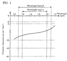
- FIG. 1 shows the chromatic dispersion characteristic of an optical fiber according to an embodiment of the present invention.
- the chromatic dispersion of the optical fiber is -20 ps ⁇ nm -1 ⁇ km -1 or more but -3 ps ⁇ nm -1 ⁇ km -1 or less in the whole wavelength range of 1300 nm to 1600 nm (wavelength band A).
- This wavelength band A includes the 1.31 ⁇ m band, 1.45 ⁇ m band, 1.55 ⁇ m band, and 1.58 ⁇ m band.
- a chromatic dispersion of -20 ps ⁇ nm -1 ⁇ km -1 or more enables the suppression of the waveform degradation of the light signal caused by the accumulation of the chromatic dispersions to a level not exceeding the level in the case of using a single mode fiber stipulated in G.654 of ITU at a wavelength of 1550 nm.
- a chromatic dispersion of -3 ps ⁇ nm -1 ⁇ km -1 or less can restrain the waveform degradation of the light signal due to nonlinear optical phenomena. Therefore, using this optical fiber as an optical transmission line can achieve large-volume and long-haul transmission with the light signal at a plurality of wavelengths within the wavelength band A.
- the chromatic dispersion of an optical fiber according to the present invention is -12 ps ⁇ nm -1 ⁇ km -1 or more but -4 ps ⁇ nm -1 ⁇ km -1 or less at all wavelengths in the wavelength band A.
- a chromatic dispersion of -12 ps ⁇ nm 1 ⁇ km -1 or more can more effectively suppress the waveform degradation of the light signal caused by the accumulation of the chromatic dispersions; a chromatic dispersion of -4 ps ⁇ nm -1 ⁇ km -1 or less more effectively restrains the waveform degradation of the light signal caused by the nonlinear optical phenomena. Accordingly, larger-volume and longer-distance transmission is possible in this case, using the light signals having numerous wavelengths in the wavelength band A.
- the chromatic dispersion of an optical fiber according to the present invention is -20 ps ⁇ nm -1 ⁇ km -1 or more but -3 ps ⁇ nm -1 ⁇ km -1 or less in the whole range of wavelength band of 1250 nm to 1650 nm (wavelength band B), which is wider than the above-mentioned wavelength band A.
- wavelength band B wavelength band of 1250 nm to 1650 nm
- a further larger volume and long distance transmission is possible using the light signals having numerous wavelengths in the wavelength band B which is wider than the wavelength band A.
- the chromatic dispersion of an optical fiber according to the present invention is -16 ps ⁇ nm -1 ⁇ km -1 or more but -4 ps ⁇ nm -1 ⁇ km -1 or less at all of the wavelengths in wavelength band B.
- a chromatic dispersion of-16 ps ⁇ nm -1 ⁇ km -1 or more enables to more effectively suppress the waveform degradation of the light signal caused by the accumulation of the chromatic dispersions; a chromatic dispersion of - 4ps ⁇ nm -1 ⁇ km -1 or less more effectively restrains the waveform degradation of the light signal caused by the nonlinear optical phenomena. Accordingly, it is possible to make a larger-volume and longer-distance transmission, using the light signal of numerous wavelengths in wavelength band B.
- the effective area of the optical fiber according to the present invention is 40 ⁇ m 2 or more at a wavelength of 1550 nm.
- the waveform degradation of the light signal caused by nonlinear optical phenomena becomes below the level of signal deterioration due to nonlinearities in the case of the dispersion-shifted optical fiber that is stipulated in G.653 of ITU, and hence it is suitable for performing a long-haul transmission.
- the increase in loss due to the OH group of the optical fiber according to the present invention is preferably -0,1dB ⁇ km -1 or less at a wavelength of 1380 nm.
- a wavelength near the 1380 nm wavelength can also be used as the light signal wavelength, it is possible to make a larger- volume transmission.
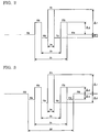
- the refractive index profile shown in Figure 2 has, in the order of enumeration from the center of the optical axis, a central core region (refractive index n 1 , outer diameter 2a), a second core region (refractive index n 2 , outer diameter 2b), a third core region (refractive index n 3 , outer diameter 2c), and a clad region (refractive index n 4 ).
- the size relations of the respective refractive indexes are n 1 >n 2 , n 2 ⁇ n 3 , and n 3 > n 4 .
- the relative refractive index difference ⁇ 1 of the central core region is from 0.4 % to 0.7 % based on the refractive index of the outermost layer of the clad region.
- An optical fiber having such a refractive index profile can be obtained by adding on the silica glass basis, for example, GeO 2 to both the central core region and the third core region, and/or F element to both the second core region and the clad region.
- the refractive index profile shown in Figure 3 is such that the clad region in the refractive index profile of Figure 2 is replaced by an inner clad region (refractive index n 4 , outer diameter 2d) and an outer clad region (refractive index n 5 ), wherein n 4 ⁇ n 5 .
- the relative refractive index difference ⁇ 1 of the central core region is from 0.4 % to 0.7 % based on the refractive index of the outermost layer of the outer clad region.
- An optical fiber having such a refractive index profile can be obtained by adding on the silica glass basis, for example, GeO 2 to both the central core region and the third core region, and/or F element to both the second core region and the inner clad region.
- optical fibers of the implementation examples have the refractive index profiles shown in Figure 3.
- Figure 4 is a graph showing the chromatic dispersion characteristics of each of the optical fibers in the implementation examples.
- each optical fiber in the first through fourth implementation examples is -20 ps ⁇ nm -1 ⁇ km -1 or more but -3 ps ⁇ nm -1 ⁇ km -1 or less at all wavelengths in the wavelength band A as well as the wavelength band B. Also, each optical fiber in the first through fourth implementation examples has an effective area of 40 ⁇ m or more at a wavelength of 1550 nm and loss increase of 0,1dB ⁇ km -1 or less due to OH group at a wavelength of 1380 nm.
- the chromatic dispersion of each optical fiber in the first through third implementation examples is -12 ps ⁇ nm -1 ⁇ km -1 or more but -4 ps ⁇ nm -1 ⁇ km -1 or less in all wavelengths in the wavelength band A. Also, the chromatic dispersion of the optical fiber in the third implementation example is -16 ps ⁇ nm -1 ⁇ km -1 or more but -4 ps ⁇ nm -1 ⁇ km -1 or less at all wavelengths in the wavelength band B.
- An optical transmission system 1 is provided with an optical fiber 130 as the optical transmission line between a transmitting station 110 and a receiving station 120.
- the transmitting station 110 includes N units of transmitters 111 1 - 111 N (N ⁇ 2) and an optical multiplexer 112.
- the transmitter 111 n (n is an integer of 1 or greater but not greater than N) outputs a light signal having a wavelength of ⁇ n within the wavelength band A or wavelength band B.
- the optical multiplexer 112 multiplexes the light signals of wavelengths ⁇ 1 - ⁇ N and sends out the same to the optical fiber 130.
- the optical fiber 130 transmits the multiplexed light signals having wavelengths ⁇ 1 - ⁇ N , which have been sent out by the optical multiplexer 112, to the receiving station 120.
- the optical fiber 130 exhibits the chromatic dispersions in the range of -20 ps ⁇ nm -1 ⁇ km -1 or more but -3 ps ⁇ nm -1 ⁇ km -1 or less at all wavelengths in the wavelength band A.
- the chromatic dispersion of the optical fiber 130 is preferably -12 ps ⁇ nm -1 ⁇ km -1 or more but equal to or less than -4 ps ⁇ nm -1 ⁇ km -1 at all wavelengths of the wavelength band A, or -20 ps ⁇ nm -1 ⁇ km -1 or more but equal to or less than -3 ps ⁇ n -1 ⁇ km -1 at all wavelengths of the wavelength band B. More preferably, the chromatic dispersion is -16 ps ⁇ nm -1 ⁇ km -1 or more but -4 ps ⁇ nm -1 ⁇ km -1 or less at all wavelengths in the wavelength band B.
- the effective area of the optical fiber 130 is 40 ⁇ m 2 or more at a wavelength of 1550 nm, and the loss increase due to OH group at a wavelength of 1380 nm is 0.1 dB ⁇ km -1 or less.
- the receiving station 120 includes N units of receivers 121 1 - 121 N and a demultiplexer 122.
- the demultiplexer 122 demultiplexes the multiplexed light signals having the wavelengths of ⁇ 1 - ⁇ N , which have been received through the optical fiber 130, and outputs the same.
- a receiver 121 n receives light signal having a wavelength of ⁇ n which has been output from the demultiplexer 122.
- the optical transmission system 1 since the optical fiber 130 according to the present invention as mentioned above is used as the optical transmission line between the transmitting station 110 and the receiving station 120, the waveform degradation of the light signal due to nonlinear optical phenomena as well as the waveform degradation of the light signal due to the accumulation of the chromatic dispersions are restrained at all wavelengths of the wavelength band A or the wavelength band B, including the 1.31 ⁇ m band, 1.45 ⁇ m band, 1.55 ⁇ m band, and 1.58 ⁇ m band. Therefore, the optical transmission system 1 enables a large-volume long-haul transmission using light signals having the numerous wavelengths of ⁇ 1 - ⁇ N in the wavelength band A or the wavelength band B.
- An optical transmission system 2 is provided with an optical fiber 231 as the optical transmission line between a transmitting station 210 and a relay station 240 and further provided with an optical fiber 232 as an optical transmission line between the relay station 240 and a receiving station 220.
- the transmitting station 210 includes N units of transmitters 211 1 -211 N , optical multiplexers 212 1 , 212 2 , optical amplifiers 213 1 , 213 2 , and an optical multiplexer 214.
- the transmitter 211 n outputs a light signal having wavelength ⁇ n in the wavelength band A or wavelength band B.
- the wavelengths ⁇ 1 - ⁇ N some are in 1.31 ⁇ m band, some other wavelengths are in 1.45 ⁇ m band, some other wavelengths are in 1.55 ⁇ m band, and the other wavelengths are in 1.58 ⁇ m band.
- the optical multiplexer 212 1 multiplexes light signals having wavelengths ⁇ 1 - ⁇ M in a first wavelength band which have been sent out from transmitters 211 1 - 211 M (M is an integer of 1 or greater but not greater than N).
- the optical amplifier 213 1 amplifies the multiplexed light signals having wavelengths ⁇ 1 - ⁇ M altogether, and outputs the same.
- the optical multiplexer 212 2 multiplexes light signals having wavelengths ⁇ M+1 - ⁇ N in a second wavelength band which have been sent out from the transmitters 211 M+1 - 211 N , and the optical amplifier 213 2 amplifies the multiplexed light signals having wavelengths ⁇ M+1 - ⁇ N altogether.
- the optical multiplexer 214 multiplexes the amplified light signals having wavelengths ⁇ 1 - ⁇ M and the amplified light signals having wavelengths ⁇ M+1 - ⁇ N , and sends out the same to the optical fiber 231.
- the optical fiber 231 transmits the light signals having wavelengths ⁇ 1 - ⁇ N , which have been sent out from the transmitting station 210, to the relay station 240.
- This optical fiber 231 exhibits the chromatic dispersions of -20 ps ⁇ nm -1 ⁇ km -1 or more but -3 ps ⁇ nm -1 ⁇ km -1 or less at all wavelengths of the wavelength band A.
- the chromatic dispersion of the optical fiber 231 is -12 ps ⁇ nm -1 ⁇ km -1 or more but -4 ps ⁇ nm -1 ⁇ km -1 or less at all wavelengths of the wavelength band A, or the chromatic dispersion is -20 ps ⁇ nm -1 ⁇ km -1 or more but -3 ps ⁇ nm -1 ⁇ km -1 or less at all wavelengths of the wavelength band B. More preferably, the chromatic dispersion is equal to or more than -16 ps ⁇ nm -1 ⁇ km -1 but -4 ps ⁇ nm -1 ⁇ km -1 or less at all wavelengths in the wavelength band B. Also, the effective area of the optical fiber 231 at the wavelength of 1550 nm is equal to or more than 40 ⁇ m, and the loss increase by OH group at a wavelength of 1380 nm is -0.1 dB ⁇ km or less.
- the relay station 240 includes a demultiplexer 241, optical amplifiers 242 1 , 242 2 , and an optical multiplexer 243.
- the demultiplexer 241 demultiplexes the light signals of wavelengths ⁇ 1 - ⁇ N that have reached thereto into a first wavelength band including wavelengths ⁇ 1 - ⁇ M and a second wavelength band including wavelengths ⁇ M+1 - ⁇ N .
- the optical amplifier 242 1 amplifies the light signals having the wavelengths ⁇ 1 - ⁇ M in the first wavelength band altogether, and the optical amplifier 242 2 amplifies the light signals having the wavelengths ⁇ M+ 1 - ⁇ N in the second wavelength band altogether.
- the optical multiplexer 243 multiplexes the light signals having the wavelengths ⁇ 1 - ⁇ M and the light signals having wavelength ⁇ M+1 - ⁇ N which have been amplified and output, and sends out the same to an optical fiber 232.
- the optical fiber 232 transmits the light signals having wavelength ⁇ 1 - ⁇ N , which have been sent out from the relay station 240, to the receiving station 220.
- the optical fiber 232 has the same characteristic as the optical fiber 231.
- the receiving station 220 includes N units of receivers 221 1 - 221 N , demultiplexers 222 1 , 222 2 , optical amplifiers 223 1 , 223 2 , and a demultiplexer 224.
- the demultiplexer 224 demultiplexes the light signals having wavelengths ⁇ 1 - ⁇ N , which have been received through the optical fiber 232, into a first wavelength band including wavelengths ⁇ 1 - ⁇ M and a second wavelength band including wavelengths ⁇ M+1 - ⁇ N .
- the optical amplifier 223 1 amplifies the light signals of wavelengths ⁇ 1 - ⁇ M altogether, and the demultiplexer 222 1 demultiplexes these light signals of wavelengths ⁇ 1 - ⁇ M into each wavelength.
- the optical amplifier 223 2 amplifies the light signals of wavelengths ⁇ M+1 - ⁇ N altogether, and the demultiplexer 2222 demultiplexes these light signals into each wavelength.
- the receiver 221 n receives the light signal having the wavelength ⁇ n which has been output from the demultiplexer 222 1 or 222 2 .
- the optical transmission system 2 since the optical fibers 231, 232 according to the present invention are used, as mentioned above, as the optical transmission lines between the transmitting station 210 and the relay station 240 and between relay station 240 and the receiving station 220, respectively, the waveform degradation of the light signal due to nonlinear optical phenomena as well as the waveform degradation of the light signal due to the accumulation of the chromatic dispersions are restrained at all wavelengths of the wavelength band A or the wavelength band B, including the 1.31 ⁇ m band, 1.45 ⁇ m band, 1.55 ⁇ m band, and 1.58 ⁇ m band. Therefore, the optical transmission system 2 enables a large-volume long-haul transmission using light signals having the numerous wavelengths of ⁇ 1 - ⁇ N in the wavelength band A or the wavelength band B.
- the optical amplifiers 213 1 , 242 1 , and 223 1 amplify the light signals having wavelength ⁇ 1 - ⁇ M in the first wavelength band altogether, and the optical amplifiers 213 2 , 242 2 , and 223 2 amplify the light signals having wavelengths ⁇ M+1 - ⁇ N in the second wavelength band altogether, and accordingly this enables a long-haul transmission.
- the first wavelength band includes the 1.55 and 1.58 ⁇ m band
- an erbium-doped fiber amplifier (EDFA) can be used as the optical amplifier which amplifies the light signals in the first wavelength band altogether.
- the second wavelength band includes the 1.31 ⁇ m band and 1.45 ⁇ m band, and a semiconductor optical amplifier or a Raman amplifier can be used as the optical amplifier which amplifies the light signals in the second wavelength band altogether.
- the light signals are divided into two wavelength bands and each of them is amplified by the respective optical amplifier.
- all of them may be amplified by one optical amplifier, or they may be divided into three or more wavelength bands and each of them may be amplified by a respective optical amplifier.
- the light signals may be divided into four wavelength bands: the 1.31 ⁇ m band, 1.45 ⁇ m band, 1.55 ⁇ m band, and 1.58 ⁇ m band.
- PDFA praseodymium-doped fiber amplifier
- a thulium-doped fiber amplifier can be used for the amplification of the light signal at the 1.45 ⁇ m band.
- An EDFA can be used for the amplification of the light signals at the 1.55 ⁇ m band and the 1.58 ⁇ m band, respectively.
- a semiconductor optical amplifier or a Raman amplifier can be used for the amplification of any light signal in any of the wavelength bands.
Landscapes
- Physics & Mathematics (AREA)
- General Physics & Mathematics (AREA)
- Optics & Photonics (AREA)
- Chemical & Material Sciences (AREA)
- Dispersion Chemistry (AREA)
- Optical Communication System (AREA)
Abstract
Description
- The present invention relates to a Wavelength Division Multiplexing (WDM) transmission system to perform optical transmission by multiplexing light signals having a plurality of wavelengths, and an optical fiber used as the optical transmission line for the WDM optical transmission system.
- The WDM transmission system using an optical fiber network can transmit a large volume of information. The WDM transmission system comprises a transmitter to send out light signals having a plurality of wavelengths, an optical fiber to transmit these light signals, a receiver to receive these light signals, and an optical fiber amplifier to amplify these light signals. In order to increase the transmission capacity of the WDM transmission system, an attempt has been made to expand the wavelength band used for the transmission.
- European Patent Application Publication No. EP 1037074 discloses an optical fiber that has appropriate chromatic dispersions in the whole range of wavelengths including 1.53 µm to 1.61 µm, in which the optical fiber amplifier can obtain a positive gain. The optical fiber can hence restrain the waveform degradation of the light signal due to a nonlinear optical phenomenon as well as the waveform degradation of the light signal due to the accumulation of the chromatic dispersions. The zero dispersion wavelength of this optical fiber is at least 1.61 µm but not more than 1.67 µm, and the chromatic dispersion slope at wavelength of 1.55 µm is 0.15 ps·nm-2·km-1 or less. In the implementation examples of the cited invention, optical fibers having a chromatic dispersion slope of at least 0.07 ps·nm-2·km -1 but not more than 0.15 ps·nm-2·km-1 are disclosed.
- As for the optical fibers disclosed in the above-mentioned bulletin no consideration is made about the use in 1.31 µm band and 1.45 µm band (S band ).
- An object of the present invention is to provide an optical fiber which can achieve a large-volume and long-haul transmission, using light signals having a plurality of wavelengths in the wide range of wavelengths including 1.31 µm band, 1.45 µm band, 1.55 µm band and 1.58 µm band, as well as a transmission system including such an optical fiber.
- In order to achieve this and other objects, an optical fiber is provided in which the chromatic dispersion is -20 ps·nm-1·km -1 or more but -3 ps·nm-1·km-1 or less in the whole wavelength range of 1300 nm to 1600 nm.
- Furthermore, an optical transmission system is provided which comprises (1) a plurality of transmitters to send out light signals having wavelengths in the range of 1300 nm to 1600 nm, (2) an optical fiber to transmit the light signals and the chromatic dispersions thereof are -20 ps·nm-1·km-1or more but -3 ps·nm-1·km-1or less at wavelengths in the range of 1300 nm to 1600 nm, and (3) receivers to receive the light signals.
- An optical fiber according to an embodiment of the present invention is provided with (1) a central core region including the center of optical axis and having a first refractive index, (2) a second core region enclosing the central core region and having a second refractive index which is smaller than the first refractive index, (3) a third core region enclosing the second core region and having a third refractive index which is greater than the second refractive index, and (4) a clad region enclosing the third core region and having a fourth refractive index which is smaller than the third refractive index.
- The above and further objects and novel features of the invention will be more fully clarified from the following detailed description when the same is read in connection with the accompanying drawings. It is to be expressly understood, however, that the drawings are for the purpose of illustration only and are not intended as a definition of the limits of the invention.
- For convenience to understand the drawings used in the detailed description of the present invention, a brief description of each drawing is provided:
- Figure 1 shows the chromatic dispersion characteristic of an optical fiber according to an embodiment of the present invention.
- Figure 2 shows a preferable example of the refractive index profile of an optical fiber according to an embodiment of the present invention.
- Figure 3 shows another preferable example of the refractive index profile of an optical fiber according to an embodiment of the present invention.
- Figure 4 is a graph showing the chromatic dispersion characteristic of each of the optical fibers described in the implementation examples.
- Figure 5 is a schematic diagram of an optical transmission system according to a first embodiment of the present invention.
- Figure 6 is a schematic diagram of an optical transmission system according to a second embodiment of the present invention.
-
- In the following, preferred embodiments of the present invention will be explained in detail with reference to the accompanying drawings. To facilitate the comprehension of the explanation, the same reference numerals denote the same parts, where possible, throughout the drawings, and a repeated explanation will be omitted. The dimensions in the drawing are partly exaggerated and do not always correspond to actual ratios of dimensions. Figure 1 shows the chromatic dispersion characteristic of an optical fiber according to an embodiment of the present invention. The chromatic dispersion of the optical fiber is -20 ps·nm-1·km-1 or more but -3 ps·nm-1·km-1 or less in the whole wavelength range of 1300 nm to 1600 nm (wavelength band A). This wavelength band A includes the 1.31 µm band, 1.45 µm band, 1.55 µm band, and 1.58 µm band.
- A chromatic dispersion of -20 ps·nm-1·km -1 or more enables the suppression of the waveform degradation of the light signal caused by the accumulation of the chromatic dispersions to a level not exceeding the level in the case of using a single mode fiber stipulated in G.654 of ITU at a wavelength of 1550 nm. A chromatic dispersion of -3 ps·nm-1·km-1 or less can restrain the waveform degradation of the light signal due to nonlinear optical phenomena. Therefore, using this optical fiber as an optical transmission line can achieve large-volume and long-haul transmission with the light signal at a plurality of wavelengths within the wavelength band A.
- Preferably, the chromatic dispersion of an optical fiber according to the present invention is -12 ps·nm-1·km-1 or more but -4 ps·nm-1·km-1 or less at all wavelengths in the wavelength band A. A chromatic dispersion of -12 ps·nm 1·km-1 or more can more effectively suppress the waveform degradation of the light signal caused by the accumulation of the chromatic dispersions; a chromatic dispersion of -4 ps·nm-1·km-1 or less more effectively restrains the waveform degradation of the light signal caused by the nonlinear optical phenomena. Accordingly, larger-volume and longer-distance transmission is possible in this case, using the light signals having numerous wavelengths in the wavelength band A.
- More preferably, the chromatic dispersion of an optical fiber according to the present invention is -20 ps·nm-1·km-1 or more but -3 ps·nm-1·km-1 or less in the whole range of wavelength band of 1250 nm to 1650 nm (wavelength band B), which is wider than the above-mentioned wavelength band A. In this case, a further larger volume and long distance transmission is possible using the light signals having numerous wavelengths in the wavelength band B which is wider than the wavelength band A.
- Yet more preferably, the chromatic dispersion of an optical fiber according to the present invention is -16 ps·nm-1·km-1 or more but -4 ps·nm-1 ·km-1 or less at all of the wavelengths in wavelength band B. A chromatic dispersion of-16 ps·nm-1·km-1 or more enables to more effectively suppress the waveform degradation of the light signal caused by the accumulation of the chromatic dispersions; a chromatic dispersion of - 4ps·nm-1·km-1 or less more effectively restrains the waveform degradation of the light signal caused by the nonlinear optical phenomena. Accordingly, it is possible to make a larger-volume and longer-distance transmission, using the light signal of numerous wavelengths in wavelength band B.
- Also, it is ideal that the effective area of the optical fiber according to the present invention is 40 µm2 or more at a wavelength of 1550 nm. In this case, the waveform degradation of the light signal caused by nonlinear optical phenomena becomes below the level of signal deterioration due to nonlinearities in the case of the dispersion-shifted optical fiber that is stipulated in G.653 of ITU, and hence it is suitable for performing a long-haul transmission.
- Also, the increase in loss due to the OH group of the optical fiber according to the present invention is preferably -0,1dB·km-1 or less at a wavelength of 1380 nm. In this case, because a wavelength near the 1380 nm wavelength can also be used as the light signal wavelength, it is possible to make a larger- volume transmission.
- A refractive index profile that is suitable for realizing the optical fiber according to the present invention is explained in the following. The refractive index profile shown in Figure 2 has, in the order of enumeration from the center of the optical axis, a central core region (refractive index n1,
outer diameter 2a), a second core region (refractive index n2,outer diameter 2b), a third core region (refractive index n3,outer diameter 2c), and a clad region (refractive index n4). The size relations of the respective refractive indexes are n1>n2, n2 < n3, and n3 > n4. More preferably, the relative refractive index difference ▵1 of the central core region is from 0.4 % to 0.7 % based on the refractive index of the outermost layer of the clad region. An optical fiber having such a refractive index profile can be obtained by adding on the silica glass basis, for example, GeO2 to both the central core region and the third core region, and/or F element to both the second core region and the clad region. - The refractive index profile shown in Figure 3 is such that the clad region in the refractive index profile of Figure 2 is replaced by an inner clad region (refractive index n4,
outer diameter 2d) and an outer clad region (refractive index n5), wherein n4 < n5. Preferably, the relative refractive index difference Δ1 of the central core region is from 0.4 % to 0.7 % based on the refractive index of the outermost layer of the outer clad region. An optical fiber having such a refractive index profile can be obtained by adding on the silica glass basis, for example, GeO2 to both the central core region and the third core region, and/or F element to both the second core region and the inner clad region. - Next, four implementation examples regarding the optical fiber according to the present invention are explained in reference to Table 1. The optical fibers of the implementation examples have the refractive index profiles shown in Figure 3. Figure 4 is a graph showing the chromatic dispersion characteristics of each of the optical fibers in the implementation examples.
EXAMPLES Example # 1 2 3 4 2a(µm) 5.7 5.5 5.2 5.0 2b(µm) 14.7 14.5 15.1 14.3 2c(µm) 22.5 21.3 21.6 21.6 2d(µm) 45.2 42.6 43.2 43.2 ▵n1(%) 0.50 0.55 0.57 0.59 ▵n2(%) -0.20 -0.20 -0.20 -0.15 ▵n3(%) 0.25 0.30 0.29 0.27 ▵n4(%) -0.20 -0.20 -0.20 -0.15 Chromatic dispersion (ps·nm-1·km-1) at 1250 nm -11.98 -11.82 -12.60 -16.40 at 1310 nm -9.22 -8.81 -9.42 -14.30 at 1550 nm -8.07 -6.28 -7.99 -14.70 at 1650 nm -3.81 -3.32 -7.10 -8.60 Dispersion slope (ps·nm-2·km-1) 0.016 0.011 -0.008 0.027 Effective area (µm2) 52.1 46.6 42.1 49.3 Mode field diameter (µm) 7.95 7.44 7.15 7.75 Bend loss (dB) 2.4 0.2 1.5 0.8 λ0(nm) 1694 1700 1757 1724 λc (nm) 1290 1310 1220 1330 ▵α1.38(dB·km-1) 0.01 0.06 0.03 0.03 - The chromatic dispersion of each optical fiber in the first through fourth implementation examples is -20 ps·nm-1·km-1 or more but -3 ps·nm-1·km-1 or less at all wavelengths in the wavelength band A as well as the wavelength band B. Also, each optical fiber in the first through fourth implementation examples has an effective area of 40 µm or more at a wavelength of 1550 nm and loss increase of 0,1dB·km-1 or less due to OH group at a wavelength of 1380 nm. The chromatic dispersion of each optical fiber in the first through third implementation examples is -12 ps·nm-1·km-1 or more but -4 ps·nm-1·km-1 or less in all wavelengths in the wavelength band A. Also, the chromatic dispersion of the optical fiber in the third implementation example is -16 ps·nm-1·km-1 or more but -4 ps·nm-1·km-1 or less at all wavelengths in the wavelength band B.
- Next, a first embodiment of an optical transmission system employing the optical fiber according to the present invention as an optical transmission line is explained with reference to Figure 5. An
optical transmission system 1 is provided with anoptical fiber 130 as the optical transmission line between a transmittingstation 110 and a receivingstation 120. - The transmitting
station 110 includes N units of transmitters 1111- 111N (N≧2) and anoptical multiplexer 112. The transmitter 111n (n is an integer of 1 or greater but not greater than N) outputs a light signal having a wavelength of λn within the wavelength band A or wavelength band B. Of the wavelengths λ1 to λ N, some are in 1.31 µm band, some other wavelengths are in 1.45 µm band, some other wavelengths are in 1.55 µm band and the other wavelengths are in 1.58 µm band. Theoptical multiplexer 112 multiplexes the light signals of wavelengths λ1- λN and sends out the same to theoptical fiber 130. Theoptical fiber 130 transmits the multiplexed light signals having wavelengths λ1- λN, which have been sent out by theoptical multiplexer 112, to the receivingstation 120. Theoptical fiber 130 exhibits the chromatic dispersions in the range of -20 ps·nm-1·km-1 or more but -3 ps·nm-1·km-1 or less at all wavelengths in the wavelength band A. Also, the chromatic dispersion of theoptical fiber 130 is preferably -12 ps·nm-1·km-1 or more but equal to or less than -4 ps·nm-1·km-1at all wavelengths of the wavelength band A, or -20 ps·nm-1·km-1 or more but equal to or less than -3 ps·n-1·km-1 at all wavelengths of the wavelength band B. More preferably, the chromatic dispersion is -16 ps·nm-1·km-1 or more but -4 ps·nm-1·km-1 or less at all wavelengths in the wavelength band B. Also, more preferably, the effective area of theoptical fiber 130 is 40 µm2 or more at a wavelength of 1550 nm, and the loss increase due to OH group at a wavelength of 1380 nm is 0.1 dB·km-1 or less. - The receiving
station 120 includes N units of receivers 1211 - 121N and ademultiplexer 122. Thedemultiplexer 122 demultiplexes the multiplexed light signals having the wavelengths of λ1- λN, which have been received through theoptical fiber 130, and outputs the same. A receiver 121n receives light signal having a wavelength of λn which has been output from thedemultiplexer 122. - As for this
optical transmission system 1, since theoptical fiber 130 according to the present invention as mentioned above is used as the optical transmission line between the transmittingstation 110 and the receivingstation 120, the waveform degradation of the light signal due to nonlinear optical phenomena as well as the waveform degradation of the light signal due to the accumulation of the chromatic dispersions are restrained at all wavelengths of the wavelength band A or the wavelength band B, including the 1.31 µm band, 1.45 µm band, 1.55 µm band, and 1.58 µm band. Therefore, theoptical transmission system 1 enables a large-volume long-haul transmission using light signals having the numerous wavelengths of λ1-λN in the wavelength band A or the wavelength band B. - Next, a second embodiment of an optical transmission system employing the optical fiber according to the present invention as an optical transmission line is explained with reference to Figure 6. An
optical transmission system 2 is provided with anoptical fiber 231 as the optical transmission line between a transmittingstation 210 and arelay station 240 and further provided with anoptical fiber 232 as an optical transmission line between therelay station 240 and a receivingstation 220. - The transmitting
station 210 includes N units of transmitters 2111-211N, optical multiplexers 2121, 2122, optical amplifiers 2131, 2132, and anoptical multiplexer 214. The transmitter 211n outputs a light signal having wavelength λn in the wavelength band A or wavelength band B. Of the wavelengths λ1- λN, some are in 1.31 µm band, some other wavelengths are in 1.45 µm band, some other wavelengths are in 1.55 µm band, and the other wavelengths are in 1.58 µm band. The optical multiplexer 2121 multiplexes light signals having wavelengths λ1- λM in a first wavelength band which have been sent out from transmitters 2111 - 211 M (M is an integer of 1 or greater but not greater than N). The optical amplifier 2131 amplifies the multiplexed light signals having wavelengths λ1-λM altogether, and outputs the same. The optical multiplexer 2122 multiplexes light signals having wavelengths λ M+1 - λN in a second wavelength band which have been sent out from the transmitters 211M+1 - 211N, and the optical amplifier 2132 amplifies the multiplexed light signals having wavelengths λM+1 - λN altogether. Theoptical multiplexer 214 multiplexes the amplified light signals having wavelengths λ1-λM and the amplified light signals having wavelengths λ M+1 - λN, and sends out the same to theoptical fiber 231. - The
optical fiber 231 transmits the light signals having wavelengths λ1-λN , which have been sent out from the transmittingstation 210, to therelay station 240. Thisoptical fiber 231 exhibits the chromatic dispersions of -20 ps·nm-1·km-1 or more but -3 ps·nm-1·km -1 or less at all wavelengths of the wavelength band A. Preferably, the chromatic dispersion of theoptical fiber 231 is -12 ps·nm-1·km-1 or more but -4 ps·nm-1·km-1 or less at all wavelengths of the wavelength band A, or the chromatic dispersion is -20 ps·nm-1·km-1 or more but -3 ps·nm-1·km-1 or less at all wavelengths of the wavelength band B. More preferably, the chromatic dispersion is equal to or more than -16 ps·nm-1·km-1 but -4 ps·nm-1·km-1 or less at all wavelengths in the wavelength band B. Also, the effective area of theoptical fiber 231 at the wavelength of 1550 nm is equal to or more than 40 µm, and the loss increase by OH group at a wavelength of 1380 nm is -0.1 dB·km or less. - The
relay station 240 includes ademultiplexer 241, optical amplifiers 2421, 2422, and anoptical multiplexer 243. Thedemultiplexer 241 demultiplexes the light signals of wavelengths λ1 - λN that have reached thereto into a first wavelength band including wavelengths λ1 - λM and a second wavelength band including wavelengths λM+1 - λN. The optical amplifier 2421 amplifies the light signals having the wavelengths λ1 - λM in the first wavelength band altogether, and the optical amplifier 2422 amplifies the light signals having the wavelengths λM+1 - λN in the second wavelength band altogether. Then, theoptical multiplexer 243 multiplexes the light signals having the wavelengths λ1 - λM and the light signals having wavelength λM+1 - λN which have been amplified and output, and sends out the same to anoptical fiber 232. - The
optical fiber 232 transmits the light signals having wavelength λ1 -λN, which have been sent out from therelay station 240, to the receivingstation 220. Theoptical fiber 232 has the same characteristic as theoptical fiber 231. - The receiving
station 220 includes N units of receivers 2211 - 221N, demultiplexers 2221, 2222, optical amplifiers 2231, 2232, and ademultiplexer 224. Thedemultiplexer 224 demultiplexes the light signals having wavelengths λ1 - λN, which have been received through theoptical fiber 232, into a first wavelength band including wavelengths λ1 -λM and a second wavelength band including wavelengths λM+1 - λN. The optical amplifier 2231 amplifies the light signals of wavelengths λ1 - λM altogether, and the demultiplexer 2221 demultiplexes these light signals of wavelengths λ1 - λM into each wavelength. The optical amplifier 2232 amplifies the light signals of wavelengths λM+1 - λN altogether, and thedemultiplexer 2222 demultiplexes these light signals into each wavelength. The receiver 221n receives the light signal having the wavelength λ n which has been output from the demultiplexer 2221 or 2222. - As for the
optical transmission system 2, since theoptical fibers station 210 and therelay station 240 and betweenrelay station 240 and the receivingstation 220, respectively, the waveform degradation of the light signal due to nonlinear optical phenomena as well as the waveform degradation of the light signal due to the accumulation of the chromatic dispersions are restrained at all wavelengths of the wavelength band A or the wavelength band B, including the 1.31 µm band, 1.45 µm band, 1.55 µm band, and 1.58 µm band. Therefore, theoptical transmission system 2 enables a large-volume long-haul transmission using light signals having the numerous wavelengths of λ1-λN in the wavelength band A or the wavelength band B. - Also, in this
optical transmission system 2, the optical amplifiers 2131, 2421, and 2231 amplify the light signals having wavelength λ1 - λM in the first wavelength band altogether, and the optical amplifiers 2132, 2422, and 2232 amplify the light signals having wavelengths λM+1 - λN in the second wavelength band altogether, and accordingly this enables a long-haul transmission. By way of example, the first wavelength band includes the 1.55 and 1.58 µm band, and an erbium-doped fiber amplifier (EDFA) can be used as the optical amplifier which amplifies the light signals in the first wavelength band altogether. On the other hand, the second wavelength band includes the 1.31 µm band and 1.45 µm band, and a semiconductor optical amplifier or a Raman amplifier can be used as the optical amplifier which amplifies the light signals in the second wavelength band altogether. - In the composition shown in Figure 6, the light signals are divided into two wavelength bands and each of them is amplified by the respective optical amplifier. However, all of them may be amplified by one optical amplifier, or they may be divided into three or more wavelength bands and each of them may be amplified by a respective optical amplifier. For example, the light signals may be divided into four wavelength bands: the 1.31 µm band, 1.45 µm band, 1.55 µm band, and 1.58 µm band. Then, a praseodymium-doped fiber amplifier (PDFA) can be used for the amplification of the light signal at the 1.31 µm band. A thulium-doped fiber amplifier (TDFA) can be used for the amplification of the light signal at the 1.45 µm band. An EDFA can be used for the amplification of the light signals at the 1.55 µm band and the 1.58 µm band, respectively. For the amplification of any light signal in any of the wavelength bands, a semiconductor optical amplifier or a Raman amplifier can be used.
Claims (11)
- An optical fiber whose chromatic dispersion is -20 ps·nm-1·km-1 or more but -3 ps·nm-1·km-1 or less at all of the wavelengths in the range of 1300 nm to 1600 nm.
- An optical fiber whose chromatic dispersion is -12 ps·nm-1·km-1 or more but -4 ps·nm-1·km-1 or less at all of the wavelengths in the range of 1300 nm to 1600 nm.
- An optical fiber whose chromatic dispersion is -20 ps·nm-1·km-1 or more but -3 ps·nm-1·km-1 or less at all of the wavelengths in the range of 1250 nm to 1650 nm.
- An optical fiber whose chromatic dispersion is -16 ps·nm-1·km-1 or more but -4 ps·nm-1·km-1 or less at all of the wavelengths in the range of 1250 nm to 1650 nm.
- An optical fiber according to Claim 1, wherein the effective area at an wavelength of 1550 nm is 40 µm2 or more.
- An optical fiber according to Claim 1, wherein the loss increase due to OH group at a wavelength of 1380 nm is 0.1 dB·km-1 or less.
- An optical fiber according to Claim 1, wherein said optical fiber is provided with (1) a central core region including the center of optical axis and having a first refractive index, (2) a second core region enclosing the central core region and having a second refractive index which is smaller than the first refractive index, (3) a third core region enclosing the second core region and having a third refractive index which is greater than the second refractive index, and (4) a clad region enclosing the third core region and having a fourth refractive index which is smaller than the third refractive index.
- An optical fiber according to Claim 7, wherein said clad region includes an inner clad region having a refractive index smaller than said third refractive index and an outer clad region having a refractive index greater than the refractive index of the inner clad region.
- An optical fiber according to Claim 7, wherein the relative refractive index difference of said central core region is 0.4% or more but 0.7% or less with respect to the refractive index of the outermost layer of said clad region.
- An optical transmission system comprising:a transmitting station to send out light signals having wavelengths in the range of 1300 nm to 1600 nm after multiplexing the same;an optical fiber according to Claim 1 to transmit said light signals; anda receiving station to receive said light signals and demultiplex the same into their respective wavelengths.
- An optical transmission system comprising:a transmitting station to send out light signals having wavelengths in the range of 1250 nm to 1650 nm after multiplexing the same;an optical fiber according to Claim 3 to transmit said light signals; anda receiving station to receive said light signals and demultiplex the same into their respective wavelengths.
Applications Claiming Priority (6)
| Application Number | Priority Date | Filing Date | Title |
|---|---|---|---|
| JP35326299 | 1999-12-13 | ||
| JP35327099 | 1999-12-13 | ||
| JP35327099A JP2001166173A (en) | 1999-12-13 | 1999-12-13 | Optical fiber |
| JP35326299A JP4134468B2 (en) | 1999-12-13 | 1999-12-13 | Optical fiber |
| JP2000132652A JP5028706B2 (en) | 2000-05-01 | 2000-05-01 | Optical fiber and optical transmission system |
| JP2000132652 | 2000-05-01 |
Publications (2)
| Publication Number | Publication Date |
|---|---|
| EP1111414A2 true EP1111414A2 (en) | 2001-06-27 |
| EP1111414A3 EP1111414A3 (en) | 2007-08-08 |
Family
ID=27341446
Family Applications (1)
| Application Number | Title | Priority Date | Filing Date |
|---|---|---|---|
| EP00125219A Ceased EP1111414A3 (en) | 1999-12-13 | 2000-11-22 | Optical fiber and optical transmission system |
Country Status (5)
| Country | Link |
|---|---|
| US (1) | US6856738B2 (en) |
| EP (1) | EP1111414A3 (en) |
| CN (1) | CN1199061C (en) |
| AU (1) | AU7194200A (en) |
| CA (1) | CA2327128A1 (en) |
Cited By (3)
| Publication number | Priority date | Publication date | Assignee | Title |
|---|---|---|---|---|
| EP1318419A1 (en) * | 2001-12-06 | 2003-06-11 | Fitel Usa Corporation | Dispersion compensating optical fibre with quadruple clad |
| FR2845486A1 (en) * | 2002-10-07 | 2004-04-09 | Cit Alcatel | OPTICAL FIBER WITH CHROMATIC DISPERSION COMPENSATION |
| FR2849214A1 (en) * | 2002-12-24 | 2004-06-25 | Cit Alcatel | OPTICAL FIBER WITH CHROMATIC DISPERSION COMPENSATION IN THE BAND S |
Families Citing this family (7)
| Publication number | Priority date | Publication date | Assignee | Title |
|---|---|---|---|---|
| US20040062495A1 (en) * | 2002-09-26 | 2004-04-01 | Sumitomo Electric Industries, Ltd. | Optical fiber product and method of fabricating thereof, Raman amplifier and method of fabricating thereof, method of fabricating of optical coupler, and optical transmission line |
| US20040218881A1 (en) * | 2003-04-30 | 2004-11-04 | Jacob Rathje | Method for the manufacture of optical fibers and improved optical fibers |
| US20080056955A1 (en) * | 2006-08-31 | 2008-03-06 | Maswadeh Waleed M | Ultra-trace sample concentrator and methods of use |
| CN100495091C (en) * | 2007-06-01 | 2009-06-03 | 中国科学院上海光学精密机械研究所 | Double-clad single-mode ytterbium-doped fiber with leaky structure and large mode field |
| WO2010000750A1 (en) * | 2008-06-30 | 2010-01-07 | Alcatel Lucent | Device for switching optical signals |
| JP6233100B2 (en) * | 2014-03-03 | 2017-11-22 | 富士通株式会社 | Optical amplification repeater and optical transmission station |
| CN110749953B (en) * | 2019-10-29 | 2023-07-14 | 长飞光纤光缆股份有限公司 | Low-dispersion single-mode optical fiber |
Family Cites Families (15)
| Publication number | Priority date | Publication date | Assignee | Title |
|---|---|---|---|---|
| US4435040A (en) * | 1981-09-03 | 1984-03-06 | Bell Telephone Laboratories, Incorporated | Double-clad optical fiberguide |
| US4715679A (en) * | 1981-12-07 | 1987-12-29 | Corning Glass Works | Low dispersion, low-loss single-mode optical waveguide |
| CA1248386A (en) * | 1982-03-11 | 1989-01-10 | Leonard G. Cohen | Quadruple-clad optical fiberguide |
| US5553185A (en) | 1994-12-27 | 1996-09-03 | Corning Incorporated | Controlled dispersion optical waveguide |
| US5684909A (en) | 1996-02-23 | 1997-11-04 | Corning Inc | Large effective area single mode optical waveguide |
| TW339377B (en) | 1996-09-30 | 1998-09-01 | Mitsui Petroleum Chemicals Ind | Flexible nonwoven fabric and laminate thereof |
| EP0868043A2 (en) | 1997-03-26 | 1998-09-30 | Nortel Networks Corporation | Multiplexed optical transmission systems |
| US6131415A (en) * | 1997-06-20 | 2000-10-17 | Lucent Technologies Inc. | Method of making a fiber having low loss at 1385 nm by cladding a VAD preform with a D/d<7.5 |
| JPH1184159A (en) | 1997-09-10 | 1999-03-26 | Furukawa Electric Co Ltd:The | Dispersion flat fiber |
| CA2312717A1 (en) | 1997-12-05 | 1999-06-17 | Sumitomo Electric Industries, Ltd. | Dispersion-shifted optical fiber |
| US6396986B1 (en) | 1998-04-22 | 2002-05-28 | Corning Incorporated | Method of making optical fibers |
| EP1141754B1 (en) * | 1998-12-18 | 2008-09-03 | Prysmian Cavi e Sistemi Energia S.r.l. | Optical fiber for metropolitan and access network systems |
| JP2001166173A (en) * | 1999-12-13 | 2001-06-22 | Sumitomo Electric Ind Ltd | Optical fiber |
| JP4134468B2 (en) * | 1999-12-13 | 2008-08-20 | 住友電気工業株式会社 | Optical fiber |
| US6636677B2 (en) * | 2000-02-28 | 2003-10-21 | Sumitomo Electric Industries, Ltd. | Optical fiber |
-
2000
- 2000-11-22 EP EP00125219A patent/EP1111414A3/en not_active Ceased
- 2000-11-30 CA CA002327128A patent/CA2327128A1/en not_active Abandoned
- 2000-11-30 AU AU71942/00A patent/AU7194200A/en not_active Abandoned
- 2000-12-11 US US09/732,725 patent/US6856738B2/en not_active Expired - Fee Related
- 2000-12-13 CN CN00135579.1A patent/CN1199061C/en not_active Expired - Fee Related
Non-Patent Citations (1)
| Title |
|---|
| LIU Y ET AL: "DESIGN AND FABRICATION OF LOCALLY DISPERSION-FLATTENED LARGE EFFECTIVE AREA FIBERS", PROCEEDINGS OF THE EUROPEAN CONFERENCE ON OPTICALCOMMUNICATION, XX, XX, vol. 1, 20 September 1998 (1998-09-20), pages 37/38, XP000879650 * |
Cited By (11)
| Publication number | Priority date | Publication date | Assignee | Title |
|---|---|---|---|---|
| EP1318419A1 (en) * | 2001-12-06 | 2003-06-11 | Fitel Usa Corporation | Dispersion compensating optical fibre with quadruple clad |
| US6633715B2 (en) | 2001-12-06 | 2003-10-14 | Fitel Usa Corp. | Optical fiber having negative dispersion, negative dispersion slope and large effective area |
| FR2845486A1 (en) * | 2002-10-07 | 2004-04-09 | Cit Alcatel | OPTICAL FIBER WITH CHROMATIC DISPERSION COMPENSATION |
| WO2004034110A1 (en) * | 2002-10-07 | 2004-04-22 | Draka Comteq Bv | Optical fibre with chromatic dispersion compensation |
| US7006743B2 (en) | 2002-10-07 | 2006-02-28 | Alcatel | Chromatic dispersion compensation optical fiber |
| EP1855130A1 (en) * | 2002-10-07 | 2007-11-14 | Draka comteq B.V. | Optical fibre with chromatic dispersion compensation. |
| CN101251618B (en) * | 2002-10-07 | 2010-10-06 | 德雷卡通信技术公司 | A Dispersion Compensating Optical Fiber |
| FR2849214A1 (en) * | 2002-12-24 | 2004-06-25 | Cit Alcatel | OPTICAL FIBER WITH CHROMATIC DISPERSION COMPENSATION IN THE BAND S |
| EP1434071A1 (en) * | 2002-12-24 | 2004-06-30 | Alcatel | Chromatic dispersion compensating optical fibre in the S-band |
| US7171092B2 (en) | 2002-12-24 | 2007-01-30 | Alcatel | Optical fiber with chromatic dispersion compensation in the S band |
| EP1865348A3 (en) * | 2002-12-24 | 2008-09-17 | Draka comteq B.V. | Optical fibre with S-band chromatic dispersion compensation |
Also Published As
| Publication number | Publication date |
|---|---|
| US6856738B2 (en) | 2005-02-15 |
| US20010019653A1 (en) | 2001-09-06 |
| CN1299979A (en) | 2001-06-20 |
| EP1111414A3 (en) | 2007-08-08 |
| AU7194200A (en) | 2001-06-14 |
| CA2327128A1 (en) | 2001-06-13 |
| CN1199061C (en) | 2005-04-27 |
Similar Documents
| Publication | Publication Date | Title |
|---|---|---|
| EP1116970A1 (en) | Optical transmission line | |
| EP1146358A1 (en) | Optical fiber and optical transmission system including the same | |
| US6684016B2 (en) | Optical fiber for wavelength division multiplexing optical transmission system using densely spaced optical channels | |
| US6862391B2 (en) | Optical transmission line, and optical fiber and dispersion compensating module employed in the same | |
| US6459839B1 (en) | Phase-shifted monomode optical fibre with large effective area | |
| WO2020056264A1 (en) | Bismuth doped fiber amplifier | |
| US6856738B2 (en) | Optical fiber and optical transmission system | |
| JP4259186B2 (en) | Optical transmission system | |
| US6791744B2 (en) | Raman amplification optical fiber, optical fiber coil, raman amplifier, and optical communication system | |
| US6522819B2 (en) | Optical fiber and optical transmission line using the optical fiber | |
| CA2379871A1 (en) | Dispersion compensation system | |
| US6778748B2 (en) | Optical fiber, dispersion compensator using the same, and optical transmission system | |
| US6668121B2 (en) | Optical fiber, and dispersion compensator using same, optical transmission line using same and optical transmission system using same | |
| US7068876B1 (en) | Method and system for optical transmission adopting dispersion compensation | |
| US7085463B2 (en) | Optical fiber and optical transmission line | |
| US6865326B2 (en) | Optical transmission line and optical transmission system | |
| US7289710B2 (en) | Optical fiber suitable for high-speed large-scale wdm system, optical transmission line and optical transmission system using the same | |
| US6850680B2 (en) | Chromatic dispersion compensating fiber for use in U band optical fiber transmission systems | |
| EP1189315A2 (en) | Optical amplifier and optical transmission system using same | |
| JP5028706B2 (en) | Optical fiber and optical transmission system | |
| US20040202439A1 (en) | Dispersion-shifted fiber | |
| US6804046B2 (en) | Optical amplification fiber, fiber optic amplifier, and optical communication system |
Legal Events
| Date | Code | Title | Description |
|---|---|---|---|
| PUAI | Public reference made under article 153(3) epc to a published international application that has entered the european phase |
Free format text: ORIGINAL CODE: 0009012 |
|
| AK | Designated contracting states |
Kind code of ref document: A2 Designated state(s): AT BE CH CY DE DK ES FI FR GB GR IE IT LI LU MC NL PT SE TR |
|
| AX | Request for extension of the european patent |
Free format text: AL;LT;LV;MK;RO;SI |
|
| PUAL | Search report despatched |
Free format text: ORIGINAL CODE: 0009013 |
|
| AK | Designated contracting states |
Kind code of ref document: A3 Designated state(s): AT BE CH CY DE DK ES FI FR GB GR IE IT LI LU MC NL PT SE TR |
|
| AX | Request for extension of the european patent |
Extension state: AL LT LV MK RO SI |
|
| 17P | Request for examination filed |
Effective date: 20071205 |
|
| AKX | Designation fees paid |
Designated state(s): DE FR GB IT |
|
| 17Q | First examination report despatched |
Effective date: 20080320 |
|
| STAA | Information on the status of an ep patent application or granted ep patent |
Free format text: STATUS: THE APPLICATION HAS BEEN REFUSED |
|
| 18R | Application refused |
Effective date: 20110415 |