EP1111321A2 - Beaded plate for a heat exchanger and method of making same - Google Patents
Beaded plate for a heat exchanger and method of making same Download PDFInfo
- Publication number
- EP1111321A2 EP1111321A2 EP00311351A EP00311351A EP1111321A2 EP 1111321 A2 EP1111321 A2 EP 1111321A2 EP 00311351 A EP00311351 A EP 00311351A EP 00311351 A EP00311351 A EP 00311351A EP 1111321 A2 EP1111321 A2 EP 1111321A2
- Authority
- EP
- European Patent Office
- Prior art keywords
- beaded
- heat exchanger
- plate
- beads
- plates
- Prior art date
- Legal status (The legal status is an assumption and is not a legal conclusion. Google has not performed a legal analysis and makes no representation as to the accuracy of the status listed.)
- Withdrawn
Links
- 238000004519 manufacturing process Methods 0.000 title abstract description 9
- 239000011324 bead Substances 0.000 claims abstract description 61
- 239000012530 fluid Substances 0.000 claims abstract description 22
- 239000003507 refrigerant Substances 0.000 description 19
- 238000009826 distribution Methods 0.000 description 11
- 238000000034 method Methods 0.000 description 10
- 239000000463 material Substances 0.000 description 6
- 238000005219 brazing Methods 0.000 description 4
- 230000009977 dual effect Effects 0.000 description 4
- 239000002826 coolant Substances 0.000 description 2
- 238000009828 non-uniform distribution Methods 0.000 description 2
- 239000000956 alloy Substances 0.000 description 1
- 229910045601 alloy Inorganic materials 0.000 description 1
- WYTGDNHDOZPMIW-RCBQFDQVSA-N alstonine Natural products C1=CC2=C3C=CC=CC3=NC2=C2N1C[C@H]1[C@H](C)OC=C(C(=O)OC)[C@H]1C2 WYTGDNHDOZPMIW-RCBQFDQVSA-N 0.000 description 1
- 229910052782 aluminium Inorganic materials 0.000 description 1
- XAGFODPZIPBFFR-UHFFFAOYSA-N aluminium Chemical compound [Al] XAGFODPZIPBFFR-UHFFFAOYSA-N 0.000 description 1
- 238000005452 bending Methods 0.000 description 1
- 238000005253 cladding Methods 0.000 description 1
- 239000004020 conductor Substances 0.000 description 1
- 230000003247 decreasing effect Effects 0.000 description 1
- 238000007723 die pressing method Methods 0.000 description 1
- 230000002708 enhancing effect Effects 0.000 description 1
- 238000010438 heat treatment Methods 0.000 description 1
- 239000007788 liquid Substances 0.000 description 1
- 239000007769 metal material Substances 0.000 description 1
- 238000012986 modification Methods 0.000 description 1
- 230000004048 modification Effects 0.000 description 1
- 238000011144 upstream manufacturing Methods 0.000 description 1
Images


Classifications
-
- F—MECHANICAL ENGINEERING; LIGHTING; HEATING; WEAPONS; BLASTING
- F28—HEAT EXCHANGE IN GENERAL
- F28F—DETAILS OF HEAT-EXCHANGE AND HEAT-TRANSFER APPARATUS, OF GENERAL APPLICATION
- F28F3/00—Plate-like or laminated elements; Assemblies of plate-like or laminated elements
- F28F3/02—Elements or assemblies thereof with means for increasing heat-transfer area, e.g. with fins, with recesses, with corrugations
- F28F3/04—Elements or assemblies thereof with means for increasing heat-transfer area, e.g. with fins, with recesses, with corrugations the means being integral with the element
- F28F3/042—Elements or assemblies thereof with means for increasing heat-transfer area, e.g. with fins, with recesses, with corrugations the means being integral with the element in the form of local deformations of the element
- F28F3/044—Elements or assemblies thereof with means for increasing heat-transfer area, e.g. with fins, with recesses, with corrugations the means being integral with the element in the form of local deformations of the element the deformations being pontual, e.g. dimples
-
- F—MECHANICAL ENGINEERING; LIGHTING; HEATING; WEAPONS; BLASTING
- F28—HEAT EXCHANGE IN GENERAL
- F28F—DETAILS OF HEAT-EXCHANGE AND HEAT-TRANSFER APPARATUS, OF GENERAL APPLICATION
- F28F3/00—Plate-like or laminated elements; Assemblies of plate-like or laminated elements
-
- F—MECHANICAL ENGINEERING; LIGHTING; HEATING; WEAPONS; BLASTING
- F28—HEAT EXCHANGE IN GENERAL
- F28D—HEAT-EXCHANGE APPARATUS, NOT PROVIDED FOR IN ANOTHER SUBCLASS, IN WHICH THE HEAT-EXCHANGE MEDIA DO NOT COME INTO DIRECT CONTACT
- F28D1/00—Heat-exchange apparatus having stationary conduit assemblies for one heat-exchange medium only, the media being in contact with different sides of the conduit wall, in which the other heat-exchange medium is a large body of fluid, e.g. domestic or motor car radiators
- F28D1/02—Heat-exchange apparatus having stationary conduit assemblies for one heat-exchange medium only, the media being in contact with different sides of the conduit wall, in which the other heat-exchange medium is a large body of fluid, e.g. domestic or motor car radiators with heat-exchange conduits immersed in the body of fluid
- F28D1/03—Heat-exchange apparatus having stationary conduit assemblies for one heat-exchange medium only, the media being in contact with different sides of the conduit wall, in which the other heat-exchange medium is a large body of fluid, e.g. domestic or motor car radiators with heat-exchange conduits immersed in the body of fluid with plate-like or laminated conduits
- F28D1/0308—Heat-exchange apparatus having stationary conduit assemblies for one heat-exchange medium only, the media being in contact with different sides of the conduit wall, in which the other heat-exchange medium is a large body of fluid, e.g. domestic or motor car radiators with heat-exchange conduits immersed in the body of fluid with plate-like or laminated conduits the conduits being formed by paired plates touching each other
- F28D1/0325—Heat-exchange apparatus having stationary conduit assemblies for one heat-exchange medium only, the media being in contact with different sides of the conduit wall, in which the other heat-exchange medium is a large body of fluid, e.g. domestic or motor car radiators with heat-exchange conduits immersed in the body of fluid with plate-like or laminated conduits the conduits being formed by paired plates touching each other the plates having lateral openings therein for circulation of the heat-exchange medium from one conduit to another
- F28D1/0333—Heat-exchange apparatus having stationary conduit assemblies for one heat-exchange medium only, the media being in contact with different sides of the conduit wall, in which the other heat-exchange medium is a large body of fluid, e.g. domestic or motor car radiators with heat-exchange conduits immersed in the body of fluid with plate-like or laminated conduits the conduits being formed by paired plates touching each other the plates having lateral openings therein for circulation of the heat-exchange medium from one conduit to another the plates having integrated connecting members
- F28D1/0341—Heat-exchange apparatus having stationary conduit assemblies for one heat-exchange medium only, the media being in contact with different sides of the conduit wall, in which the other heat-exchange medium is a large body of fluid, e.g. domestic or motor car radiators with heat-exchange conduits immersed in the body of fluid with plate-like or laminated conduits the conduits being formed by paired plates touching each other the plates having lateral openings therein for circulation of the heat-exchange medium from one conduit to another the plates having integrated connecting members with U-flow or serpentine-flow inside the conduits
Definitions
- the present invention relates generally to heat exchangers and, more specifically, to a beaded plate and method of making same for a heat exchanger in a motor vehicle.
- the heat exchanger includes opposed plates carrying a first fluid medium in contact with an interior thereof while a second fluid medium contacts an exterior thereof.
- the first fluid medium is a refrigerant and the second fluid medium is air. Where a temperature difference exists between the first and second fluid mediums, heat will be transferred between the two via heat conductive walls of the plates.
- Performance of heat exchanger cores such as evaporator cores has been directly linked to refrigerant flow distribution through the core. This includes the flow distribution in a flow header or tank and tube or plate areas. It is known that an effective way of generating a more uniform flow through the channel is by using a large plenum area upstream of the channel. Therefore, there is a need in the art to enhance the thermal performance in the heat exchanger core through the enhancement of coolant flow distribution inside the core.
- the effectiveness of the refrigerant flow distribution through the core is measured by the thermal performance, refrigerant pressure drop, and an infrared thermal image of the core skin temperature. Nonuniform distribution of flow starts at the tank area of the core.
- the refrigerant pressure drop inside the core is controlled by several factors: heat transfer from the core to the air; flow restriction inside the core; nonuniform distribution of the refrigerant inside the core; and the change of phase from liquid to vapor because vapor has a higher pressure drop.
- the pressure drop can increase significantly when any combination or all of these factors are taking place together. Therefore, there is a need in the art to provide a heat exchanger with increased core thermal capacity, minimum increase in refrigerant pressure drop and minimum air temperature non-uniformity.
- the present invention is a beaded plate for a heat exchanger including a plate having a generally planar surface with an inlet and an outlet.
- the beaded plate also includes a plurality of beads extending generally perpendicular to the surface of the plate.
- the beaded plate further includes a restriction in at least one of the inlet and the outlet to restrict fluid flow.
- the present invention is a method of making a beaded plate for a heat exchanger.
- the method includes the steps of providing a plate having a generally planar surface with an inlet and an outlet.
- the method also includes the steps of forming a plurality of beads to extend generally perpendicular to the surface of the plate and forming a restriction in at least one of the inlet and outlet to restrict fluid flow.
- a beaded plate for a heat exchanger such as an evaporator is provided for a motor vehicle.
- the beaded plate has an additional bead in an inlet area for equalizing flow for a plate-fin heat exchanger such as an evaporator.
- the beaded plate has an adjustable bead in the inlet area which improves heat transfer by generating more uniform refrigerant flow.
- the beaded plate may have a uniform inlet/outlet restriction in a plate-fin heat exchanger such as an evaporator.
- a further advantage of the present invention is that the beaded plate may have a uniform inlet/outlet restriction to improve the refrigerant flow distribution inside the tank. Yet a further advantage of the present invention is that a method of making the beaded plate is provided with either an adjustable bead or a uniform inlet/outlet restriction. Still a further advantage of the present invention is that the beaded plate may have a variable inlet/outlet restriction to improve refrigerant flow distribution inside the tank while allowing for a smaller heat exchanger and maintaining performance.
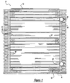
- Figure 1 is an elevational view of a beaded plate, according to the present invention, illustrated in operational relationship with a heat exchanger.
- Figure 2 is a fragmentary plan view of the beaded plate of Figure 1.
- Figure 3 is an enlarged fragmentary plan view of a portion of the beaded plate of Figure 2.
- Figure 4 is a view similar to Figure 3 of another embodiment, according to the present invention, of the beaded plate of Figure 1.
- Figure 5 is a graph of heat exchanger core performance as a function of the beaded plate inlet/outlet restriction.
- Figure 6 is a graph of heat exchanger core refrigerant pressure drop as a function of the beaded plate inlet/outlet restriction.
- Figure 7 is a view similar to Figure 3 of yet another embodiment, according to the present invention, of the beaded plate of Figure 1.
- Figure 8 is a sectional view taken along line 8-8 of Figure 7.
- Figure 9 is a view similar to Figure 3 of still another embodiment, according to the present invention, of the beaded plate of Figure 1.
- Figure 10 is a sectional view taken along line 10-10 of Figure 9.
- a heat exchanger 10 such as an oil cooler, evaporator or condenser, is shown for a motor vehicle (not shown).
- the heat exchanger 10 includes a plurality of generally parallel beaded plates 12, according to the present invention, pairs of which are joined together in a face-to-face relationship to provide a channel (not shown) therebetween.
- the heat exchanger 10 also includes a plurality of convoluted or serpentine fins 14 attached an exterior of each of the beaded plates 12. The fins 14 are disposed between each pair of the joined beaded plates 12 to form a stack.
- the fins 14 serve as a means for conducting heat away from the beaded plates 12 while providing additional surface area for convective heat transfer by air flowing over the heat exchanger 10.
- the heat exchanger 10 further includes oppositely disposed mounting plates 16 at ends of the stack.
- the mounting plates 16 fluidly communicate with flow headers, generally indicated at 18, formed by bosses 19 on each of the beaded plates 12.
- the heat exchanger 10 includes a fluid inlet 20 for conducting fluid into the heat exchanger 10 formed in the flow header 18 and a fluid outlet 22 for directing fluid out of the heat exchanger 10 formed in the flow header 18. It should be appreciated that, except for the beaded plates 12, the heat exchanger 10 is conventional and known in the art. It should also be appreciated that the beaded plates 12 and heat exchanger 10 could be used in other applications besides motor vehicles.
- the beaded plate 12 extends longitudinally and is substantially planar or flat.
- the beaded plate 12 includes a raised boss 19 on at least one end having a pair of apertures 24 and 26 spaced laterally and extending therethrough.
- the bosses 19 are stacked together such that the apertures 24 and 26 are aligned to form the flow header 18 to allow parallel flow of fluid through the channels of the beaded plates 12. It should be appreciated that such flow headers 18 are conventional and known in the art.
- the beaded plate 12 includes a surface 28 being generally planar and extending longitudinally and laterally.
- the beaded plate 12 also includes an inlet 30 and an outlet 32 spaced transversely and divided by a wall 34 for U-shaped flow through the channels of the beaded plates 12.
- the beaded plate 12 includes a plurality of first beads 36 extending above and generally perpendicular to a plane of the surface 28 and spaced laterally from each other.
- the first beads 36 are generally elongated in shape.
- the beaded plate 12 has at least one additional or second bead 38 at either the inlet 30 or the outlet 32 to provide a restriction to the refrigerant flow.
- the second bead 38 may have an adjustable height, which allows for a different restriction area through the flow header 18 to allow for more uniform flow distribution.
- the second bead 38 has a predetermined height. It should be appreciated that the height of the second bead 38 is adjustable by varying the same from heat exchanger to heat exchanger. It should also be appreciated that, by adding the additional second bead 38 in either the inlet 30 or outlet 32, a restriction is formed in the inlet 30 or outlet 32, respectively, which will cause the flow header 18 to act as a plenum and will increase the coolant velocity, thereby enhancing heat transfer too. It should further be appreciated that, by adding the second bead 38 to the first row in either the inlet 30 or outlet 32, a variable restriction is created in either the inlet 30 or outlet 32 of the beaded plate 12.
- the first beads 36 are formed in a plurality of rows, preferably three first beads 36 and one second bead 38 in the first row at either the inlet 30 or the outlet 32 and three first beads 36 in the other rows, which are repeated, to the inlet 30 or outlet 32, respectively.
- the rows of first beads 36 are spaced longitudinally a predetermined distance.
- the first beads 36 are formed in an 'A' and 'B' row pattern so that no first bead 36 in the A row is directly downstream of another first bead 36 in the B row.
- the first beads 36 are non-aligned in the streamwise or longitudinal direction.
- the A and B rows are repeated in the streamwise or longitudinal direction. It should be appreciated that an A and B row pattern is conventional and known in the art.
- the beaded plates 12 are made of a metal material such as aluminum or an alloy thereof and have a cladding on their inner and outer surfaces for brazing.
- the beaded plates 12 are formed from a single sheet of material and are interconnected by deformable tabs 40 to be described.
- a sheet of material can either be of a predetermined length with a predetermined number of beaded plates 12 or may be formed as a continuous strip of material, which is cut at a predetermined number of beaded plates 12 to form the heat exchanger 10 of a predetermined size.
- the beaded plates 12 are stamped using pneumatic and/or hydraulic activated details in a die controlled by a PLC ⁇ PLS or other computerized means known in the die pressing art.
- a pair of the beaded plates 12 are arranged such that the beads 36 and 38 contact each other to turbulate fluid flow therethrough. It should be appreciated that the beads 36 and 38 are brazed to each other. It should also be appreciated that the entire heat exchanger 10 is brazed together as is known in the art.
- the heat exchanger 10 includes a first set and a second set of the deformable tabs 40 connecting the beaded plates 12 together. As illustrated, each first set of tabs 40 connects adjacent beaded plates 12 near one end and each second set of tabs 40 connects adjacent beaded plates 12 near an opposite end.
- the tabs 40 extend transversely from one beaded plate 12 to another beaded plate 12 and are formed as part of a rail edge of each beaded plate 12.
- the tabs 40 are made from the same material as the beaded plates 12 and are plastically deformable.
- the tabs 40 have a single bend zone which allows for much more narrow bending to accomplish good plate-to-plate contact during the forming of the heat exchanger 10 in a continuous corrugated production process by the bellows-like or zig-zag folding of the contiguous beaded plates 12. It should be appreciated that the tabs 40 are similar to those disclosed in U.S. Patent Nos. 5,732,460 and 5,855,240, the disclosures of both being hereby incorporated by reference. It should also be appreciated that the beaded plates 12 may be used for both single and dual tank evaporator type heat exchangers with a continuous corrugation production process.
- the beaded plate 112 may distribute the refrigerant flow more uniformly inside the flow header 118 for the heat exchanger 10 by using a uniform restriction in the inlet 130 and outlet 132 of the beaded plate 112.
- the beaded plate 112 may include at least one additional second bead 138 added to both the inlet 130 and the outlet 132 to form a restriction such as fifteen percent of the area of the inlet 130 and outlet 132.
- the restriction improves the core performance significantly with more uniform flow distribution of the refrigerant in the flow header area.
- the size of the restriction for the inlet 130 was determined using the data in Figures 5 and 6. This data was plotted as a function of the non-dimensional quantity:
- the lateral space between the first beads 136 may vary for each beaded plate 112. It should also be appreciated that the restriction can be applied to both single and dual tank evaporator type heat exchangers.
- the beaded plate 12 restricts fluid flow by using a restriction in either one of or both the inlet 230 and outlet 232 of the beaded plate 212.
- the beaded plate 112 may include at least one additional second bead 238 added to either one or both the inlet 230 and the outlet 232 to form a restriction such as fifteen percent of the area of the inlet 230 and outlet 232.
- the second bead 238 is disposed and extends laterally between the first beads 236 and a wall of the beaded plate 212, preferably in the first row of the first beads 236 to form the restriction.
- the second beads 238 have a height less than a height of the first beads 236.
- the restriction improves the core performance significantly with more uniform flow distribution of the refrigerant in the flow header area. It should be appreciated that the height of the second beads 238 may vary for each beaded plate 212. It should also be appreciated that the restriction can be applied to both single and dual tank evaporator type heat exchangers.
- the beaded plate 312 restricts fluid flow by using a restriction in either one of or both the inlet 330 and outlet 332 of the beaded plate 312.
- the beaded plate 312 includes the first beads 336 decreasing in height from the inlet 330 to the outlet 332 or from the outlet 332 to the inlet 330 to form a restriction such as fifteen percent of the area of the inlet 230 and outlet 232.
- the restriction improves the core performance significantly with more uniform flow distribution of the refrigerant in the flow header area.
- the height of the first beads 336 may vary for each beaded plate 312.
- the restriction can be applied to both single and dual tank evaporator type heat exchangers.
- the method includes the step of providing a plate having a generally planar surface 28,128,228,328.
- the method includes the step of forming a plurality of first beads 36,136,236,336 to extend above the surface 28,128,228,328 of the plate.
- the method includes the step of forming a restriction in either one or both of an inlet 30,130,230,330 and outlet 32,132,232,332 of the plate to restrict fluid flow.
- the step of forming may be to form at least one second bead 38,138,238 or vary the height of the first beads 336.
- the steps of forming are carried out by stamping the beads 36,136,236,336,38,138,238 in the plate by conventional stamping processes.
- the height or size of the beads 36,136,236,336,38,138,238 could be such that the beads 36,136,236,336,38,138,238 are relatively large at the beginning, then progressively get smaller near the end.
- the method includes the step of contacting first and second beaded plates 12,112,212,312 with each other to form a channel therebetween and contacting opposed beads 36,136,236,336,38,138 with each other to form fluid flow passages.
- the method includes the step of brazing a pair of the beaded plates 12,112,212,312 by heating the beaded plates 12,112,212,312 to a predetermined temperature to melt the brazing material to braze the bosses 19,119,219,319 and the beads 36,136,236,336, 38,138 of the beaded plates 12,112,212,312 together.
- the pair of joined beaded plates 12,112,212,312 is then cooled to solidify the molten braze material to secure the bosses 19,119,219,339 together and the beads 36, 136,236,336,38,138 together.
- the method includes the step of disposing fins 14 between joined pairs of the beaded plates 12,112,212,312 and brazing the fins 14 and beaded plates 12,112,212,312 together.
- the method includes the steps of connecting the mounting plates 16 to the brazed fins 14 and beaded plates 12,112,212,312 to form the heat exchanger 10.
Landscapes
- Engineering & Computer Science (AREA)
- Physics & Mathematics (AREA)
- Thermal Sciences (AREA)
- Mechanical Engineering (AREA)
- General Engineering & Computer Science (AREA)
- Heat-Exchange Devices With Radiators And Conduit Assemblies (AREA)
Abstract
The beaded plate (12) further includes a restriction (38) in at least one of the inlet (30) and the outlet (32) to restrict fluid flow.
Description
- The present invention relates generally to heat exchangers and, more specifically, to a beaded plate and method of making same for a heat exchanger in a motor vehicle.
- It is known to provide plates for a heat exchanger such as an evaporator in a motor vehicle. Generally, the heat exchanger includes opposed plates carrying a first fluid medium in contact with an interior thereof while a second fluid medium contacts an exterior thereof. Typically, the first fluid medium is a refrigerant and the second fluid medium is air. Where a temperature difference exists between the first and second fluid mediums, heat will be transferred between the two via heat conductive walls of the plates.
- It is also known to provide beaded plates for a heat exchanger in which beads define a plurality of passageways between the plates for movement of a fluid therethrough to increase the surface area of conductive material available for heat transfer and to cause turbulence of the fluid carried in a channel between the plates. An example of such a heat exchanger is disclosed in U.S. Patent No. 4,600,053. In this patent, each of the plates has a plurality of beads formed thereon with one plate having one distinct variety of beads and the other plate having another distinct variety of beads. The beads of the plates contact each other and are bonded together to force fluid to flow therearound.
- Performance of heat exchanger cores such as evaporator cores has been directly linked to refrigerant flow distribution through the core. This includes the flow distribution in a flow header or tank and tube or plate areas. It is known that an effective way of generating a more uniform flow through the channel is by using a large plenum area upstream of the channel. Therefore, there is a need in the art to enhance the thermal performance in the heat exchanger core through the enhancement of coolant flow distribution inside the core.
- The effectiveness of the refrigerant flow distribution through the core is measured by the thermal performance, refrigerant pressure drop, and an infrared thermal image of the core skin temperature. Nonuniform distribution of flow starts at the tank area of the core.
- The refrigerant pressure drop inside the core is controlled by several factors: heat transfer from the core to the air; flow restriction inside the core; nonuniform distribution of the refrigerant inside the core; and the change of phase from liquid to vapor because vapor has a higher pressure drop. The pressure drop can increase significantly when any combination or all of these factors are taking place together. Therefore, there is a need in the art to provide a heat exchanger with increased core thermal capacity, minimum increase in refrigerant pressure drop and minimum air temperature non-uniformity.
- Therefore, it is desirable to restrict the flow in either the inlet or outlet of the plates to improve refrigerant flow distribution of a heat exchanger. It is also desirable to provide beaded plates for a heat exchanger having a uniform inlet/outlet restriction of a refrigerant in the heat exchanger. It is further desirable to provide beaded plates for a heat exchanger that improve heat transfer by generating more uniform refrigerant flow. It is still further desirable to provide a variable inlet/outlet restriction in a beaded plate for a heat exchanger.
- Accordingly, the present invention is a beaded plate for a heat exchanger including a plate having a generally planar surface with an inlet and an outlet. The beaded plate also includes a plurality of beads extending generally perpendicular to the surface of the plate. The beaded plate further includes a restriction in at least one of the inlet and the outlet to restrict fluid flow.
- Also, the present invention is a method of making a beaded plate for a heat exchanger. The method includes the steps of providing a plate having a generally planar surface with an inlet and an outlet. The method also includes the steps of forming a plurality of beads to extend generally perpendicular to the surface of the plate and forming a restriction in at least one of the inlet and outlet to restrict fluid flow.
- One advantage of the present invention is that a beaded plate for a heat exchanger such as an evaporator is provided for a motor vehicle. Another advantage of the present invention is that the beaded plate has an additional bead in an inlet area for equalizing flow for a plate-fin heat exchanger such as an evaporator. Yet another advantage of the present invention is that the beaded plate has an adjustable bead in the inlet area which improves heat transfer by generating more uniform refrigerant flow. Still another advantage of the present invention is that the beaded plate may have a uniform inlet/outlet restriction in a plate-fin heat exchanger such as an evaporator. A further advantage of the present invention is that the beaded plate may have a uniform inlet/outlet restriction to improve the refrigerant flow distribution inside the tank. Yet a further advantage of the present invention is that a method of making the beaded plate is provided with either an adjustable bead or a uniform inlet/outlet restriction. Still a further advantage of the present invention is that the beaded plate may have a variable inlet/outlet restriction to improve refrigerant flow distribution inside the tank while allowing for a smaller heat exchanger and maintaining performance.
- Other features and advantages of the present invention will be readily appreciated, as the same becomes better understood after reading the subsequent description taken in conjunction with the accompanying drawings.
- Figure 1 is an elevational view of a beaded plate, according to the present invention, illustrated in operational relationship with a heat exchanger.
- Figure 2 is a fragmentary plan view of the beaded plate of Figure 1.
- Figure 3 is an enlarged fragmentary plan view of a portion of the beaded plate of Figure 2.
- Figure 4 is a view similar to Figure 3 of another embodiment, according to the present invention, of the beaded plate of Figure 1.
- Figure 5 is a graph of heat exchanger core performance as a function of the beaded plate inlet/outlet restriction.
- Figure 6 is a graph of heat exchanger core refrigerant pressure drop as a function of the beaded plate inlet/outlet restriction.
- Figure 7 is a view similar to Figure 3 of yet another embodiment, according to the present invention, of the beaded plate of Figure 1.
- Figure 8 is a sectional view taken along line 8-8 of Figure 7.
- Figure 9 is a view similar to Figure 3 of still another embodiment, according to the present invention, of the beaded plate of Figure 1.
- Figure 10 is a sectional view taken along line 10-10 of Figure 9.
- Referring to the drawings and in particular Figures 1 through 3, one embodiment of a
heat exchanger 10, according to the present invention, such as an oil cooler, evaporator or condenser, is shown for a motor vehicle (not shown). Theheat exchanger 10 includes a plurality of generally parallel beadedplates 12, according to the present invention, pairs of which are joined together in a face-to-face relationship to provide a channel (not shown) therebetween. Theheat exchanger 10 also includes a plurality of convoluted orserpentine fins 14 attached an exterior of each of thebeaded plates 12. Thefins 14 are disposed between each pair of the joined beadedplates 12 to form a stack. Thefins 14 serve as a means for conducting heat away from thebeaded plates 12 while providing additional surface area for convective heat transfer by air flowing over theheat exchanger 10. Theheat exchanger 10 further includes oppositely disposedmounting plates 16 at ends of the stack. Themounting plates 16 fluidly communicate with flow headers, generally indicated at 18, formed bybosses 19 on each of thebeaded plates 12. Theheat exchanger 10 includes afluid inlet 20 for conducting fluid into theheat exchanger 10 formed in theflow header 18 and afluid outlet 22 for directing fluid out of theheat exchanger 10 formed in theflow header 18. It should be appreciated that, except for thebeaded plates 12, theheat exchanger 10 is conventional and known in the art. It should also be appreciated that thebeaded plates 12 andheat exchanger 10 could be used in other applications besides motor vehicles. - Referring to Figures 1 through 3, the
beaded plate 12 extends longitudinally and is substantially planar or flat. Thebeaded plate 12 includes a raisedboss 19 on at least one end having a pair ofapertures bosses 19 are stacked together such that theapertures flow header 18 to allow parallel flow of fluid through the channels of thebeaded plates 12. It should be appreciated thatsuch flow headers 18 are conventional and known in the art. - The
beaded plate 12 includes asurface 28 being generally planar and extending longitudinally and laterally. Thebeaded plate 12 also includes aninlet 30 and anoutlet 32 spaced transversely and divided by awall 34 for U-shaped flow through the channels of the beadedplates 12. Thebeaded plate 12 includes a plurality offirst beads 36 extending above and generally perpendicular to a plane of thesurface 28 and spaced laterally from each other. Thefirst beads 36 are generally elongated in shape. Thebeaded plate 12 has at least one additional orsecond bead 38 at either theinlet 30 or theoutlet 32 to provide a restriction to the refrigerant flow. Thesecond bead 38 may have an adjustable height, which allows for a different restriction area through theflow header 18 to allow for more uniform flow distribution. Thesecond bead 38 has a predetermined height. It should be appreciated that the height of thesecond bead 38 is adjustable by varying the same from heat exchanger to heat exchanger. It should also be appreciated that, by adding the additionalsecond bead 38 in either theinlet 30 oroutlet 32, a restriction is formed in theinlet 30 oroutlet 32, respectively, which will cause theflow header 18 to act as a plenum and will increase the coolant velocity, thereby enhancing heat transfer too. It should further be appreciated that, by adding thesecond bead 38 to the first row in either theinlet 30 oroutlet 32, a variable restriction is created in either theinlet 30 oroutlet 32 of thebeaded plate 12. - As illustrated in Figures 2 and 3, the
first beads 36 are formed in a plurality of rows, preferably threefirst beads 36 and onesecond bead 38 in the first row at either theinlet 30 or theoutlet 32 and threefirst beads 36 in the other rows, which are repeated, to theinlet 30 oroutlet 32, respectively. The rows offirst beads 36 are spaced longitudinally a predetermined distance. Thefirst beads 36 are formed in an 'A' and 'B' row pattern so that nofirst bead 36 in the A row is directly downstream of anotherfirst bead 36 in the B row. Thefirst beads 36 are non-aligned in the streamwise or longitudinal direction. The A and B rows are repeated in the streamwise or longitudinal direction. It should be appreciated that an A and B row pattern is conventional and known in the art. - The
beaded plates 12 are made of a metal material such as aluminum or an alloy thereof and have a cladding on their inner and outer surfaces for brazing. Thebeaded plates 12 are formed from a single sheet of material and are interconnected bydeformable tabs 40 to be described. A sheet of material can either be of a predetermined length with a predetermined number of beadedplates 12 or may be formed as a continuous strip of material, which is cut at a predetermined number of beadedplates 12 to form theheat exchanger 10 of a predetermined size. Thebeaded plates 12 are stamped using pneumatic and/or hydraulic activated details in a die controlled by a PLC\PLS or other computerized means known in the die pressing art. In the embodiment illustrated, a pair of the beadedplates 12 are arranged such that thebeads beads entire heat exchanger 10 is brazed together as is known in the art. - The
heat exchanger 10 includes a first set and a second set of thedeformable tabs 40 connecting thebeaded plates 12 together. As illustrated, each first set oftabs 40 connectsadjacent beaded plates 12 near one end and each second set oftabs 40 connectsadjacent beaded plates 12 near an opposite end. Thetabs 40 extend transversely from onebeaded plate 12 to anotherbeaded plate 12 and are formed as part of a rail edge of eachbeaded plate 12. Thetabs 40 are made from the same material as thebeaded plates 12 and are plastically deformable. Thetabs 40 have a single bend zone which allows for much more narrow bending to accomplish good plate-to-plate contact during the forming of theheat exchanger 10 in a continuous corrugated production process by the bellows-like or zig-zag folding of thecontiguous beaded plates 12. It should be appreciated that thetabs 40 are similar to those disclosed in U.S. Patent Nos. 5,732,460 and 5,855,240, the disclosures of both being hereby incorporated by reference. It should also be appreciated that thebeaded plates 12 may be used for both single and dual tank evaporator type heat exchangers with a continuous corrugation production process. - Referring to Figure 4, another
embodiment 112, according to the present invention, of thebeaded plate 12 is shown. Like parts of thebeaded plate 12 have like reference numerals increased by one hundred (100). In this embodiment, thebeaded plate 112 may distribute the refrigerant flow more uniformly inside theflow header 118 for theheat exchanger 10 by using a uniform restriction in theinlet 130 and outlet 132 of thebeaded plate 112. Thebeaded plate 112 may include at least one additionalsecond bead 138 added to both theinlet 130 and the outlet 132 to form a restriction such as fifteen percent of the area of theinlet 130 and outlet 132. As illustrated in Figure 4, the restriction improves the core performance significantly with more uniform flow distribution of the refrigerant in the flow header area. For example, the size of the restriction for theinlet 130 was determined using the data in Figures 5 and 6. This data was plotted as a function of the non-dimensional quantity: - Inlet/Outlet Area with beads
- Inlet/Outlet Area without beads
-
- It should be appreciated that the lateral space between the
first beads 136 may vary for eachbeaded plate 112. It should also be appreciated that the restriction can be applied to both single and dual tank evaporator type heat exchangers. - Referring to Figures 7 and 8, yet another
embodiment 212, according to the present invention, of thebeaded plate 12 is shown. Like parts of thebeaded plate 12 have like reference numerals increased by two hundred (200). In this embodiment, thebeaded plate 212 restricts fluid flow by using a restriction in either one of or both theinlet 230 andoutlet 232 of thebeaded plate 212. Thebeaded plate 112 may include at least one additionalsecond bead 238 added to either one or both theinlet 230 and theoutlet 232 to form a restriction such as fifteen percent of the area of theinlet 230 andoutlet 232. As illustrated, thesecond bead 238 is disposed and extends laterally between thefirst beads 236 and a wall of thebeaded plate 212, preferably in the first row of thefirst beads 236 to form the restriction. Thesecond beads 238 have a height less than a height of thefirst beads 236. The restriction improves the core performance significantly with more uniform flow distribution of the refrigerant in the flow header area. It should be appreciated that the height of thesecond beads 238 may vary for eachbeaded plate 212. It should also be appreciated that the restriction can be applied to both single and dual tank evaporator type heat exchangers. - Referring to Figures 9 and 10, still another
embodiment 312, according to the present invention, of thebeaded plate 12 is shown. Like parts of thebeaded plate 12 have like reference numerals increased by three hundred (300). In this embodiment, thebeaded plate 312 restricts fluid flow by using a restriction in either one of or both theinlet 330 andoutlet 332 of thebeaded plate 312. Thebeaded plate 312 includes thefirst beads 336 decreasing in height from theinlet 330 to theoutlet 332 or from theoutlet 332 to theinlet 330 to form a restriction such as fifteen percent of the area of theinlet 230 andoutlet 232. The restriction improves the core performance significantly with more uniform flow distribution of the refrigerant in the flow header area. It should be appreciated that the height of thefirst beads 336 may vary for eachbeaded plate 312. It should also be appreciated that the restriction can be applied to both single and dual tank evaporator type heat exchangers. - Referring to Figures 1 through 10, a method of making the beaded plate 12,112,212,312, according to the present invention, is shown. The method includes the step of providing a plate having a generally planar surface 28,128,228,328. The method includes the step of forming a plurality of first beads 36,136,236,336 to extend above the surface 28,128,228,328 of the plate. The method includes the step of forming a restriction in either one or both of an inlet 30,130,230,330 and outlet 32,132,232,332 of the plate to restrict fluid flow. The step of forming may be to form at least one second bead 38,138,238 or vary the height of the
first beads 336. The steps of forming are carried out by stamping the beads 36,136,236,336,38,138,238 in the plate by conventional stamping processes. In another embodiment, the height or size of the beads 36,136,236,336,38,138,238 could be such that the beads 36,136,236,336,38,138,238 are relatively large at the beginning, then progressively get smaller near the end. - Also, a method of making the
heat exchanger 10, according to the present invention, is shown. The method includes the step of contacting first and second beaded plates 12,112,212,312 with each other to form a channel therebetween and contacting opposed beads 36,136,236,336,38,138 with each other to form fluid flow passages. The method includes the step of brazing a pair of the beaded plates 12,112,212,312 by heating the beaded plates 12,112,212,312 to a predetermined temperature to melt the brazing material to braze the bosses 19,119,219,319 and the beads 36,136,236,336, 38,138 of the beaded plates 12,112,212,312 together. The pair of joined beaded plates 12,112,212,312 is then cooled to solidify the molten braze material to secure the bosses 19,119,219,339 together and thebeads 36, 136,236,336,38,138 together. The method includes the step of disposingfins 14 between joined pairs of the beaded plates 12,112,212,312 and brazing thefins 14 and beaded plates 12,112,212,312 together. The method includes the steps of connecting the mountingplates 16 to the brazedfins 14 and beaded plates 12,112,212,312 to form theheat exchanger 10. - The present invention has been described in an illustrative manner. It is to be understood that the terminology which has been used is intended to be in the nature of words of description rather than of limitation.
- Many modifications and variations of the present invention are possible in light of the above teachings. Therefore, within the scope of the appended claims, the present invention may be practiced other than as specifically described.
Claims (5)
- A heat exchanger comprising:a plurality of generally parallel plates, pairs of said plates being joined together in a face-to-face relationship to provide a channel therebetween, the pairs of said plates being joined together and aligned in a stack;a plurality of fins attached an exterior of said plates and disposed between each pair of said joined plates; andsaid plates having an inlet and an outlet including a plurality of beads spaced laterally and opposing each other in said channel and a restriction in at least one of said inlet and said outlet to restrict fluid flow.
- A heat exchanger as set forth in claim 1 wherein said restriction comprises at least one second bead disposed in a first row of said beads.
- A heat exchanger as set forth in claim 1 wherein said restriction comprises at least one second bead disposed in a last row of said beads.
- A heat exchanger as set forth in claim 1 wherein said restriction comprises said beads varying in height between said inlet and said outlet.
- A heat exchanger as set forth in claim 1 wherein said restriction comprises at least one second bead extending laterally between said beads and having a height less than said beads.
Applications Claiming Priority (2)
| Application Number | Priority Date | Filing Date | Title |
|---|---|---|---|
| US46804099A | 1999-12-21 | 1999-12-21 | |
| US468040 | 1999-12-21 |
Publications (2)
| Publication Number | Publication Date |
|---|---|
| EP1111321A2 true EP1111321A2 (en) | 2001-06-27 |
| EP1111321A3 EP1111321A3 (en) | 2002-07-31 |
Family
ID=23858201
Family Applications (1)
| Application Number | Title | Priority Date | Filing Date |
|---|---|---|---|
| EP00311351A Withdrawn EP1111321A3 (en) | 1999-12-21 | 2000-12-19 | Beaded plate for a heat exchanger and method of making same |
Country Status (2)
| Country | Link |
|---|---|
| EP (1) | EP1111321A3 (en) |
| KR (1) | KR20010067466A (en) |
Cited By (1)
| Publication number | Priority date | Publication date | Assignee | Title |
|---|---|---|---|---|
| US20210108867A1 (en) * | 2012-10-16 | 2021-04-15 | The Abell Foundation, Inc. | Heat Exchanger Including Manifold |
Citations (1)
| Publication number | Priority date | Publication date | Assignee | Title |
|---|---|---|---|---|
| US4600053A (en) | 1984-11-23 | 1986-07-15 | Ford Motor Company | Heat exchanger structure |
Family Cites Families (6)
| Publication number | Priority date | Publication date | Assignee | Title |
|---|---|---|---|---|
| US5111878A (en) * | 1991-07-01 | 1992-05-12 | General Motors Corporation | U-flow heat exchanger tubing with improved fluid flow distribution |
| US5125453A (en) * | 1991-12-23 | 1992-06-30 | Ford Motor Company | Heat exchanger structure |
| DE69508320T2 (en) * | 1994-07-25 | 1999-09-09 | Sanden Corp | Heat exchanger |
| JPH08136179A (en) * | 1994-11-04 | 1996-05-31 | Zexel Corp | Laminated type heat exchanger |
| US5979544A (en) * | 1996-10-03 | 1999-11-09 | Zexel Corporation | Laminated heat exchanger |
| JP3911574B2 (en) * | 2000-01-08 | 2007-05-09 | 漢拏空調株式会社 | Plate for laminated heat exchanger with improved heat exchange performance and heat exchanger using the same |
-
2000
- 2000-12-19 EP EP00311351A patent/EP1111321A3/en not_active Withdrawn
- 2000-12-20 KR KR1020000078937A patent/KR20010067466A/en not_active Withdrawn
Patent Citations (1)
| Publication number | Priority date | Publication date | Assignee | Title |
|---|---|---|---|---|
| US4600053A (en) | 1984-11-23 | 1986-07-15 | Ford Motor Company | Heat exchanger structure |
Cited By (1)
| Publication number | Priority date | Publication date | Assignee | Title |
|---|---|---|---|---|
| US20210108867A1 (en) * | 2012-10-16 | 2021-04-15 | The Abell Foundation, Inc. | Heat Exchanger Including Manifold |
Also Published As
| Publication number | Publication date |
|---|---|
| KR20010067466A (en) | 2001-07-12 |
| EP1111321A3 (en) | 2002-07-31 |
Similar Documents
| Publication | Publication Date | Title |
|---|---|---|
| US6213158B1 (en) | Flat turbulator for a tube and method of making same | |
| US6209202B1 (en) | Folded tube for a heat exchanger and method of making same | |
| EP0646231B1 (en) | Heat exchange tubes | |
| CN100513976C (en) | Heat exchanger tube having strengthening deformations | |
| US6364006B1 (en) | Beaded plate for a heat exchanger and method of making same | |
| US5507338A (en) | Tab for an automotive heat exchanger | |
| US5890288A (en) | Method for making a heat exchanger tube | |
| US6732790B2 (en) | Single heat exchanger | |
| US20060032251A1 (en) | Flat hollow body for passing fluid therethrough, heat exchanger comprising the hollow body and process for fabricating the heat exchanger | |
| US6438840B2 (en) | Method of making continuous corrugated heat exchanger | |
| US6241012B1 (en) | Folded tube for a heat exchanger and method of making same | |
| JPH08313183A (en) | Heat exchanger and manufacture of corrugated fin therefor | |
| US5934365A (en) | Heat exchanger | |
| KR20000034912A (en) | Evaporator for an air conditioning system | |
| US20030066635A1 (en) | Turbulator with offset louvers and method of making same | |
| EP1067350B1 (en) | Beaded plate for a heat exchanger and method of making same | |
| US6571866B2 (en) | Heat exchanger and method of making same | |
| KR19990034673U (en) | heat transmitter | |
| US20110030936A1 (en) | Heat Exchanging Apparatus and Method of Making Same | |
| JPS6317391A (en) | Heat exchanger and manufacture thereof | |
| EP0736346B1 (en) | Method of making an automotive evaporator | |
| US5476140A (en) | Alternately staggered louvered heat exchanger fin | |
| AU670760B2 (en) | In tank oil cooler | |
| KR20010067466A (en) | Beaded plate for a heat exchanger and method of making same | |
| US20030188431A1 (en) | Apparatus for forming restriction in heat exchanger and method for making same |
Legal Events
| Date | Code | Title | Description |
|---|---|---|---|
| PUAI | Public reference made under article 153(3) epc to a published international application that has entered the european phase |
Free format text: ORIGINAL CODE: 0009012 |
|
| AK | Designated contracting states |
Kind code of ref document: A2 Designated state(s): AT BE CH CY DE DK ES FI FR GB GR IE IT LI LU MC NL PT SE TR |
|
| AX | Request for extension of the european patent |
Free format text: AL;LT;LV;MK;RO;SI |
|
| PUAL | Search report despatched |
Free format text: ORIGINAL CODE: 0009013 |
|
| AK | Designated contracting states |
Kind code of ref document: A3 Designated state(s): AT BE CH CY DE DK ES FI FR GB GR IE IT LI LU MC NL PT SE TR |
|
| AX | Request for extension of the european patent |
Free format text: AL;LT;LV;MK;RO;SI |
|
| 17P | Request for examination filed |
Effective date: 20020909 |
|
| AKX | Designation fees paid |
Designated state(s): DE FR GB |
|
| 17Q | First examination report despatched |
Effective date: 20030916 |
|
| GRAP | Despatch of communication of intention to grant a patent |
Free format text: ORIGINAL CODE: EPIDOSNIGR1 |
|
| RTI1 | Title (correction) |
Free format text: BEADED PLATE FOR A HEAT EXCHANGER |
|
| STAA | Information on the status of an ep patent application or granted ep patent |
Free format text: STATUS: THE APPLICATION IS DEEMED TO BE WITHDRAWN |
|
| 18D | Application deemed to be withdrawn |
Effective date: 20041129 |