EP1111259A1 - Dispositif d'accouplement entre un organe rotatif menant et un organe rotatif mené - Google Patents
Dispositif d'accouplement entre un organe rotatif menant et un organe rotatif mené Download PDFInfo
- Publication number
- EP1111259A1 EP1111259A1 EP00127889A EP00127889A EP1111259A1 EP 1111259 A1 EP1111259 A1 EP 1111259A1 EP 00127889 A EP00127889 A EP 00127889A EP 00127889 A EP00127889 A EP 00127889A EP 1111259 A1 EP1111259 A1 EP 1111259A1
- Authority
- EP
- European Patent Office
- Prior art keywords
- lever
- hinge
- flexible hinge
- flexible
- rotary member
- Prior art date
- Legal status (The legal status is an assumption and is not a legal conclusion. Google has not performed a legal analysis and makes no representation as to the accuracy of the status listed.)
- Granted
Links
- 230000008878 coupling Effects 0.000 title claims abstract description 29
- 238000010168 coupling process Methods 0.000 title claims abstract description 29
- 238000005859 coupling reaction Methods 0.000 title claims abstract description 29
- 239000000463 material Substances 0.000 claims abstract description 6
- 230000007246 mechanism Effects 0.000 claims description 14
- 238000000465 moulding Methods 0.000 claims description 4
- 206010003497 Asphyxia Diseases 0.000 claims 1
- 210000004417 patella Anatomy 0.000 claims 1
- 210000000056 organ Anatomy 0.000 description 6
- 238000005461 lubrication Methods 0.000 description 3
- 239000006185 dispersion Substances 0.000 description 2
- 238000004519 manufacturing process Methods 0.000 description 2
- 238000010422 painting Methods 0.000 description 2
- BASFCYQUMIYNBI-UHFFFAOYSA-N platinum Chemical compound [Pt] BASFCYQUMIYNBI-UHFFFAOYSA-N 0.000 description 2
- 230000005540 biological transmission Effects 0.000 description 1
- 229910052697 platinum Inorganic materials 0.000 description 1
- 238000010079 rubber tapping Methods 0.000 description 1
Images


Classifications
-
- F—MECHANICAL ENGINEERING; LIGHTING; HEATING; WEAPONS; BLASTING
- F16—ENGINEERING ELEMENTS AND UNITS; GENERAL MEASURES FOR PRODUCING AND MAINTAINING EFFECTIVE FUNCTIONING OF MACHINES OR INSTALLATIONS; THERMAL INSULATION IN GENERAL
- F16D—COUPLINGS FOR TRANSMITTING ROTATION; CLUTCHES; BRAKES
- F16D3/00—Yielding couplings, i.e. with means permitting movement between the connected parts during the drive
- F16D3/005—Yielding couplings, i.e. with means permitting movement between the connected parts during the drive incorporating leaf springs, flexible parts of reduced thickness or the like acting as pivots
-
- F—MECHANICAL ENGINEERING; LIGHTING; HEATING; WEAPONS; BLASTING
- F16—ENGINEERING ELEMENTS AND UNITS; GENERAL MEASURES FOR PRODUCING AND MAINTAINING EFFECTIVE FUNCTIONING OF MACHINES OR INSTALLATIONS; THERMAL INSULATION IN GENERAL
- F16D—COUPLINGS FOR TRANSMITTING ROTATION; CLUTCHES; BRAKES
- F16D3/00—Yielding couplings, i.e. with means permitting movement between the connected parts during the drive
- F16D3/02—Yielding couplings, i.e. with means permitting movement between the connected parts during the drive adapted to specific functions
- F16D3/04—Yielding couplings, i.e. with means permitting movement between the connected parts during the drive adapted to specific functions specially adapted to allow radial displacement, e.g. Oldham couplings
Definitions
- the invention relates to a coupling device between a driving rotary member and driven rotary member having respective axes substantially aligned.
- a coupling device of this type can be used by example to ensure a rotary link between a button and a mechanism controlled by this button ordered.
- the button is centered in a front of a switchboard while the mechanism controlled by the button order is part of an electronic card or a molded plate incorporating power tracks.
- the coupling device can be used in particular for ensure coupling between an associated control button to a motor vehicle control panel for control a mechanism such as, for example, a potentiometer or an electrical switch mounted on an electronic card having no connection with the front of the control panel.
- Control panels of this type usually include a facade carrying several rotary buttons including the respective axes are intended to drive mechanisms rotating behind the facade.
- the object of the invention is in particular to overcome the drawbacks cited above.
- the invention provides for this purpose a coupling device of the type defined in the introduction, which comprises a first lever secured to the axis of the rotating driving member and a second lever secured to the axis of the driven rotary member, said first lever and second lever having a given angular offset and having respective ends away from the respective axes, as well as a flexible hinge connected to the ends of the levers.
- the coupling device of the invention consists of two levers integral with the respective axes of the organ rotary drive and rotary drive, and a hinge flexible connecting the two levers.
- This device can be easily made, generates a minimum space, and does not require lubrication.
- the flexible hinge includes a central part connected to two extreme parts via two deformable regions.
- the two regions deformable of the flexible hinge are arranged to define two axes of articulation substantially parallel to each other and to the respective axes of the driving rotary member and of the member rotary driven.
- the two regions deformable of the flexible hinge are arranged to define two ball joints.
- the flexible hinge is made in the form of a strip of substantially constant section, and the two deformable regions are formed by thinning or constriction located in the strip.
- the section of the strip is preferably substantially rectangular.
- the first lever, the second lever and the flexible hinge are made in one piece from a semi rigid material.
- first lever, the second lever and the flexible hinge are made as three separate pieces, and the hinge flexible is assembled at the respective ends of the first lever and the second lever.
- the flexible hinge is made in one piece with one of the first lever and the second lever while the other of these levers is made as a separate part.
- the hinge flexible is advantageously produced by molding a material semi-rigid plastic.
- the angular offset between the first lever and the second lever is preferably less than 90 °.
- the device comprises a push-type switch, or "push”, combined with the organ rotary driven and suitable for being actuated by an axial thrust exerted on the axis of the rotating driving member and transmitted by deformation of the coupling device.
- the organ rotary drive is a control button that is part of a control panel, while the driven rotary member is a mechanism that is part of an electronic card or overmolded platinum.
- Figure 1 shows a device coupling 10 according to the invention, interposed between a rotary drive 12 and a rotary drive 14, which are integral in rotation with respective axes 16 and 18 substantially aligned.
- the rotary member leading 12 is a control button
- the rotary member led 14 is a controlled mechanism, for example a potentiometer, an electrical switch, etc.
- the control button 12 is usually centered on a facade of a painting control (not shown) while the driven rotary member 14 is placed behind the facade.
- the coupling device 10 makes it possible to produce such a catching up. It includes a first lever 20 integral with axis 16 of the rotating member 12 and a second lever 22 integral with the axis 18 of the driven rotary member 14.
- the levers 20 and 22 extend radially with respect to the axes respective 16 and 18 and they include ends respective 24 and 26 each distant from the corresponding axis.
- levers 20 and 22 are spaced apart in the axial direction while being close from each other and they have an angular offset A which, in the example of FIG. 4, is close to 60 °.
- levers 20 and 22 are joined by a hinge flexible 28 which has a shape approaching that of a arc.
- the flexible hinge 28 comprises a part central 30 connected to two end parts 32 and 34 by through two deformable regions 36 and 38.
- the extreme parts 32 and 34 are respectively attached to ends 24 and 26 of levers 20 and 22.
- the two levers 20 and 22 as well as the flexible hinge 28 are, in the example, formed in one piece by molding of a semi-rigid plastic.
- the flexible hinge 28 is produced in the form of a strip of rectangular section, substantially constant, and both deformable regions 36 and 38 are formed by thinning located in the strip. These two deformable regions 36 and 38 define two axes of articulation X1 and X2 which are substantially parallel to each other and parallel to the axes 16 and 18.
- the deformable regions 36 and 38 are each obtained by a thinning forming a U-shaped groove, so that the thickness band is minimal in the area near the bottom of the groove to facilitate deformation.
- the flexible hinge 28 constitutes a connecting element which can be described as flexible or semi rigid insofar as it allows a transmission of movement between the driving organ and the organ led with a backlash due to offset, even minimal, axes 16 and 18.
- the device coupling 10 is similar to that of FIG. 1, except with regard to the realization of the deformable regions.
- the central part 30 is here connected to the parts extremes 32, 34 via two deformable regions 40 and 42 which are arranged to define two connections to ball joints.
- these two deformable regions have the each forms two trunks of pyramids with a rectangular base opposite from the top.
- the central part 30 can move relative at the end portions 32 and 34 by connections of the type ball joint, and not by hinge-type connections, which provides additional degrees of freedom.
- the coupling device of FIG. 2 is interesting to use when not only axes 16 and 18 are likely to be shifted but also that they can be non-parallel.
- the device coupling 10 is made in one piece, which means that levers 20 and 22, as well as the hinge flexible 28 are made in one piece by molding the plastic material.
- axes 16 and 18 are also made in one piece with the device coupling.
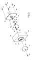
- the rotary member 12 is a button rotary to be centered in a control panel 44 produced in the form of a housing suitable for being integrated, by example, in a dashboard of a motor vehicle.
- the control panel 44 has a front panel 46 provided with a was central 48 for the passage of axis 16. It was east surrounded by an annular groove 50 to receive a skirt 52 that includes the button 12. The latter is subject to the axis 16 by a self-tapping screw 54.
- the pin 16 is formed in one piece with the lever 20 and this the latter has a groove 56 in which can be embedded the end part 32 of the flexible hinge 28. This embedding can be done in force and possibly be completed by bonding to ensure final assembly between the end portion 32 of the flexible hinge 28 and the lever 20.
- the control panel 44 in the form of a housing, defines a light pipe capable of at least partially illuminating the control button 12 and the front panel 46, the latter being fitted with appropriate symbols or pictograms (not shown) to identify the position taken by the rotary driving member 12, which forms a control button.
- the control panel 44 has a rear face open 58 ( Figures 4 to 6) into which is embedded an electronic card 60 ( Figures 3 and 5).
- This card electronics has four openings 62 suitable for being crossed by four screws 64 to allow its mounting at the back of the control panel.
- Card 62 carries, in its central part, the driven rotary member 14 which is here a controlled mechanism, such as a potentiometer or switch, can be controlled by axis 18.
- the lever 22 is attached to a ring 66 which can be wedged on the end of axis 18 to make a connection in rotation.
- the lever 22 has a groove 68 in which can be fitted to the end part 34 of the flexible hinge to make a final assembly.
- the flexible hinge 28 of the embodiment of the figures 3 to 6 comprises, as in the case of FIG. 1, two deformable regions 36, 38 obtained by thinning located in the form of gorges.
- first lever 20, the second lever 22 and the flexible hinge 28 are made of as long as three separate pieces and the flexible hinge is assembled at the respective ends of the two levers.
- the coupling device in two parts: one first part constituted by the flexible hinge and one of the levers, and another part constituted by the other lever.
- the device coupling may include a switch type push, also called push type, combined with the organ rotary driven 14 and suitable for being actuated by a push axial exerted on the axis 16 of the rotary member driving 12 and transmitted by deformation of the coupling device.
- a switch type push also called push type
- the axial distance between the axis 16 and the ring 66 ( Figure 3) is very small (a few tenths of a millimeter), or even zero.
- the coupling device is sufficiently rigid and elastic so that when you press on the button 12 and therefore on the axis 16, the coupling device deforms to transmit force in the direction axial and thus operate the push switch which is combined with the driven rotary member.
- the device of the invention thus makes it possible to produce a coupling between two rotary members by catching the possible offset of their respective axes.
- the device allows the connection of two rotating members whose distance in the direction axial shows greater dispersion.
- the invention finds a particular application in paintings used in particular in vehicles automobiles.
Landscapes
- Engineering & Computer Science (AREA)
- General Engineering & Computer Science (AREA)
- Mechanical Engineering (AREA)
- Mechanical Control Devices (AREA)
- Pivots And Pivotal Connections (AREA)
- Casings For Electric Apparatus (AREA)
Abstract
Description
- la figure 1 est une vue schématique en perspective d'un dispositif d'accouplement selon une première forme de réalisation de l'invention;
- la figure 2 est une vue schématique en perspective d'un dispositif d'accouplement selon une deuxième forme de réalisation de l'invention ;
- la figure 3 est une vue en perspective éclatée d'un bouton rotatif centré sur un tableau de commande et relié à un mécanisme rotatif d'une carte électronique par l'intermédiaire d'un dispositif d'accouplement selon l'invention ;
- la figure 4 est une vue arrière du tableau de commande de la figure 3 ;
- la figure 5 est une vue en coupe selon la ligne V-V de la figure 4 ; et
- la figure 6 est une vue en coupe selon la ligne VI-VI de la figure 5.
Claims (13)
- Dispositif d'accouplement entre un organe rotatif menant et un organe rotatif mené ayant des axes respectifs sensiblement alignés,
caractérisé en ce qu'il comprend un premier levier (20) solidaire de l'axe (16) de l'organe rotatif menant (12) et un second levier (22) solidaire de l'axe (18) de l'organe rotatif mené (14), lesdits premier levier (20) et second levier (22) présentant un décalage angulaire donné (A) et ayant des extrémités respectives (24, 26) éloignées des axes respectifs (16, 18), ainsi qu'une charnière souple (28) reliée aux extrémités (24, 26) des leviers. - Dispositif selon la revendication 1, caractérisé en ce que la charnière souple (28) comprend une partie centrale (30) reliée à deux parties extrêmes (32, 34) par l'intermédiaire de deux régions déformables (36, 38 ; 40, 42).
- Dispositif selon la revendication 2, caractérisé en ce que les deux régions déformables (36, 38) de la charnière souple (28) sont agencées pour définir deux axes d'articulation (X1, X2) sensiblement parallèles entre eux et aux axes respectifs (16, 18) de l'organe rotatif menant (12) et de l'organe rotatif mené (14).
- Dispositif selon la revendication 2, caractérisé en ce que les deux régions déformables (40, 42) de la charnière souple (28) sont agencées pour définir deux liaisons à rotule.
- Dispositif selon l'une des revendications 2 à 4, caractérisé en ce que la charnière souple (28) est réalisée sous la forme d'une bande de section sensiblement constante, et en ce que les deux régions déformables (36, 38 ; 40, 42) sont formées par des amincissements ou étranglements localisés de la bande.
- Dispositif selon la revendication 5, caractérisé en ce que la section de la bande est sensiblement rectangulaire.
- Dispositif selon l'une des revendications 1 à 6, caractérisé en ce que le premier levier (20), le second levier (22) et la charnière souple (28) sont réalisées d'une seule pièce en une matière semi rigide.
- Dispositif selon l'une des revendications 1 à 6, caractérisé en ce que le premier levier (20), le second levier (22) et la charnière souple (28) sont réalisés en tant que trois pièces séparées et en ce que la charnière souple (28) est assemblée aux extrémités respectives (24, 26) du premier levier (20) et du second levier (22).
- Dispositif selon l'une des revendications 1 à 6, caractérisé en ce que la charnière souple (28) est réalisée d'une seule pièce avec l'un du premier levier (20) et du second levier (22), tandis que l'autre de ces leviers est réalisé en tant que pièce séparée.
- Dispositif selon l'une des revendications 1 à 9, caractérisé en ce que la charnière souple (28) est réalisée par moulage d'une matière plastique semi-rigide.
- Dispositif selon l'une des revendications 1 à 10, caractérisé en ce que le décalage angulaire (A) entre le premier levier () et le second levier est inférieur à 90°.
- Dispositif selon l'une des revendications 1 à 11, caractérisé en ce qu'il comprend un commutateur du type à poussée, ou "push", combiné à l'organe rotatif mené (14) et propre à être actionné par une poussée axiale exercée sur l'axe (16) de l'organe rotatif menant (12) et transmise par déformation du dispositif d'accouplement.
- Dispositif selon l'une des revendications 1 à 12, caractérisé en ce que l'organe rotatif menant (12) est un bouton de commande faisant partie d'un tableau de commande (44), tandis que l'organe rotatif mené (14) est un mécanisme faisant partie d'une carte électronique (62) ou d'une platine surmoulée.
Applications Claiming Priority (2)
| Application Number | Priority Date | Filing Date | Title |
|---|---|---|---|
| FR9916261 | 1999-12-22 | ||
| FR9916261A FR2802993B1 (fr) | 1999-12-22 | 1999-12-22 | Dispositif d'accouplement entre un organe rotatif menant et un organe rotatif mene |
Publications (2)
| Publication Number | Publication Date |
|---|---|
| EP1111259A1 true EP1111259A1 (fr) | 2001-06-27 |
| EP1111259B1 EP1111259B1 (fr) | 2007-05-30 |
Family
ID=9553640
Family Applications (1)
| Application Number | Title | Priority Date | Filing Date |
|---|---|---|---|
| EP00127889A Expired - Lifetime EP1111259B1 (fr) | 1999-12-22 | 2000-12-20 | Dispositif d'accouplement entre un organe rotatif menant et un organe rotatif mené |
Country Status (4)
| Country | Link |
|---|---|
| EP (1) | EP1111259B1 (fr) |
| DE (1) | DE60035021T2 (fr) |
| ES (1) | ES2288146T3 (fr) |
| FR (1) | FR2802993B1 (fr) |
Cited By (2)
| Publication number | Priority date | Publication date | Assignee | Title |
|---|---|---|---|---|
| CN111810517A (zh) * | 2020-06-11 | 2020-10-23 | 广东工业大学 | 一种基于双轴柔性铰链的空间微位移导向机构 |
| CN115980963A (zh) * | 2022-12-20 | 2023-04-18 | 苏州吉天星舟空间技术有限公司 | 一种应用于背部单点支撑的反射镜柔性支撑结构 |
Citations (10)
| Publication number | Priority date | Publication date | Assignee | Title |
|---|---|---|---|---|
| US3405539A (en) * | 1966-06-13 | 1968-10-15 | Gen Motors Corp | Flexible rotary joint |
| US3618339A (en) * | 1970-01-30 | 1971-11-09 | Dow Chemical Co | Universal joint |
| US3832908A (en) * | 1973-03-01 | 1974-09-03 | Motorola Inc | One piece plastic tuning shaft for a radio receiver or the like device |
| US4197765A (en) * | 1976-10-18 | 1980-04-15 | Sakae Tsushin Kogyo Co. Ltd. | Dial apparatus |
| DE3324008A1 (de) * | 1983-07-04 | 1983-11-24 | Adalbert Dipl.-Ing. 6791 Queidersbach Leis | Biegefederkupplung |
| EP0101796A2 (fr) * | 1982-07-27 | 1984-03-07 | Dr. Johannes Heidenhain GmbH | Accouplement d'arbres |
| DE3829568A1 (de) * | 1987-09-02 | 1989-04-06 | Elektra Bregenz Ag | Verfahren zum betaetigen einer achse eines steuer- bzw. regelelementes eines geraetes |
| FR2682728A1 (fr) * | 1991-10-21 | 1993-04-23 | Sfim | Articulation a la cardan plane, procede de realisation, gyroscope et support orientable comportant une telle articulation. |
| DE4211619A1 (de) * | 1992-04-07 | 1993-10-14 | Schmidt Kupplung Gmbh | Kupplung zum winkeltreuen Kuppeln drehbarer Teile |
| FR2784148A1 (fr) * | 1998-10-02 | 2000-04-07 | Valeo Electronique | Dispositif d'accouplement entre un bouton de commande et un mecanisme |
-
1999
- 1999-12-22 FR FR9916261A patent/FR2802993B1/fr not_active Expired - Lifetime
-
2000
- 2000-12-20 EP EP00127889A patent/EP1111259B1/fr not_active Expired - Lifetime
- 2000-12-20 ES ES00127889T patent/ES2288146T3/es not_active Expired - Lifetime
- 2000-12-20 DE DE60035021T patent/DE60035021T2/de not_active Expired - Lifetime
Patent Citations (10)
| Publication number | Priority date | Publication date | Assignee | Title |
|---|---|---|---|---|
| US3405539A (en) * | 1966-06-13 | 1968-10-15 | Gen Motors Corp | Flexible rotary joint |
| US3618339A (en) * | 1970-01-30 | 1971-11-09 | Dow Chemical Co | Universal joint |
| US3832908A (en) * | 1973-03-01 | 1974-09-03 | Motorola Inc | One piece plastic tuning shaft for a radio receiver or the like device |
| US4197765A (en) * | 1976-10-18 | 1980-04-15 | Sakae Tsushin Kogyo Co. Ltd. | Dial apparatus |
| EP0101796A2 (fr) * | 1982-07-27 | 1984-03-07 | Dr. Johannes Heidenhain GmbH | Accouplement d'arbres |
| DE3324008A1 (de) * | 1983-07-04 | 1983-11-24 | Adalbert Dipl.-Ing. 6791 Queidersbach Leis | Biegefederkupplung |
| DE3829568A1 (de) * | 1987-09-02 | 1989-04-06 | Elektra Bregenz Ag | Verfahren zum betaetigen einer achse eines steuer- bzw. regelelementes eines geraetes |
| FR2682728A1 (fr) * | 1991-10-21 | 1993-04-23 | Sfim | Articulation a la cardan plane, procede de realisation, gyroscope et support orientable comportant une telle articulation. |
| DE4211619A1 (de) * | 1992-04-07 | 1993-10-14 | Schmidt Kupplung Gmbh | Kupplung zum winkeltreuen Kuppeln drehbarer Teile |
| FR2784148A1 (fr) * | 1998-10-02 | 2000-04-07 | Valeo Electronique | Dispositif d'accouplement entre un bouton de commande et un mecanisme |
Cited By (2)
| Publication number | Priority date | Publication date | Assignee | Title |
|---|---|---|---|---|
| CN111810517A (zh) * | 2020-06-11 | 2020-10-23 | 广东工业大学 | 一种基于双轴柔性铰链的空间微位移导向机构 |
| CN115980963A (zh) * | 2022-12-20 | 2023-04-18 | 苏州吉天星舟空间技术有限公司 | 一种应用于背部单点支撑的反射镜柔性支撑结构 |
Also Published As
| Publication number | Publication date |
|---|---|
| EP1111259B1 (fr) | 2007-05-30 |
| DE60035021D1 (de) | 2007-07-12 |
| DE60035021T2 (de) | 2008-01-31 |
| FR2802993A1 (fr) | 2001-06-29 |
| ES2288146T3 (es) | 2008-01-01 |
| FR2802993B1 (fr) | 2002-04-26 |
Similar Documents
| Publication | Publication Date | Title |
|---|---|---|
| EP2889205B1 (fr) | Ensemble d'une armature de face avant de véhicule automobile et d'un support destiné à supporter un actionneur | |
| WO2003002363A1 (fr) | Module d'equipement d'un vehicule automobile | |
| EP0161369A1 (fr) | Equerre de liaison pour réaliser l'assemblage de deux profilés | |
| FR2849123A1 (fr) | Liaison autobloquante entre une tige a rotule et une partie plane | |
| WO2020233879A1 (fr) | Agencement de montage d'un systeme optique sur un element de carrosserie d'un vehicule | |
| EP0931711B1 (fr) | Système de direction pour véhicule automobile | |
| EP1111259B1 (fr) | Dispositif d'accouplement entre un organe rotatif menant et un organe rotatif mené | |
| EP1660843B1 (fr) | Actionneur universel notamment pour application aux tableaux de bord | |
| FR2784148A1 (fr) | Dispositif d'accouplement entre un bouton de commande et un mecanisme | |
| EP1941118B1 (fr) | Dispositif d'ouverture de vitre arriere et/ou coffre de vehicule | |
| EP0577499A1 (fr) | Manette pour commutateur électrique, notamment pour véhicule automobile | |
| EP1111260B1 (fr) | Dispositif d'accouplement entre un organe rotatif menant et un organe rotatif mené, en particulier pour tableau de commande | |
| EP1162095A1 (fr) | Ensemble d'aérateur occultable pour véhicule automobile et équipement correspondant | |
| FR2538139A1 (fr) | Organe ou dispositif de commande manuelle pour entrainements de positionnement sur les vehicules automobiles | |
| EP2193942B1 (fr) | Boîtier de commande muni d'un système de verrouillage pour un arbre de commande | |
| WO1992015796A1 (fr) | Dispositif d'accouplement mecanique separable | |
| FR3064813B1 (fr) | Ensemble d'elements de transmission de force pour commutateur | |
| EP0997329B1 (fr) | Dispositif de commande pour installation de chauffage | |
| EP0843248B1 (fr) | Système d'activation débrayable d'un organe fonctionnel de véhicule automobile | |
| FR3155152A1 (fr) | Actionneur pour un bras robotisé à configuration améliorée | |
| EP4556759A1 (fr) | Dispositif d actionnement pour système de transmission | |
| WO2022229722A1 (fr) | Organe de commande rotatif, ensemble commande et appareil le comprenant | |
| FR2742244A1 (fr) | Systeme d'activation debrayable d'un organe fonctionnel de vehicule automobile | |
| FR2737445A1 (fr) | Dispositif de commande de flux destine a la commande de la temperature dans un vehicule automobile comportant un systeme d'air conditionne | |
| FR3104188A1 (fr) | Clé pour véhicule améliorée |
Legal Events
| Date | Code | Title | Description |
|---|---|---|---|
| PUAI | Public reference made under article 153(3) epc to a published international application that has entered the european phase |
Free format text: ORIGINAL CODE: 0009012 |
|
| AK | Designated contracting states |
Kind code of ref document: A1 Designated state(s): DE ES GB IT |
|
| AX | Request for extension of the european patent |
Free format text: AL;LT;LV;MK;RO;SI |
|
| 17P | Request for examination filed |
Effective date: 20011214 |
|
| AKX | Designation fees paid |
Free format text: DE ES GB IT |
|
| GRAP | Despatch of communication of intention to grant a patent |
Free format text: ORIGINAL CODE: EPIDOSNIGR1 |
|
| GRAS | Grant fee paid |
Free format text: ORIGINAL CODE: EPIDOSNIGR3 |
|
| RAP1 | Party data changed (applicant data changed or rights of an application transferred) |
Owner name: VALEO CLIMATISATION |
|
| RAP1 | Party data changed (applicant data changed or rights of an application transferred) |
Owner name: VALEO SYSTEMES THERMIQUES |
|
| GRAA | (expected) grant |
Free format text: ORIGINAL CODE: 0009210 |
|
| AK | Designated contracting states |
Kind code of ref document: B1 Designated state(s): DE ES GB IT |
|
| REG | Reference to a national code |
Ref country code: GB Ref legal event code: FG4D Free format text: NOT ENGLISH |
|
| REF | Corresponds to: |
Ref document number: 60035021 Country of ref document: DE Date of ref document: 20070712 Kind code of ref document: P |
|
| GBV | Gb: ep patent (uk) treated as always having been void in accordance with gb section 77(7)/1977 [no translation filed] |
Effective date: 20070530 |
|
| REG | Reference to a national code |
Ref country code: ES Ref legal event code: FG2A Ref document number: 2288146 Country of ref document: ES Kind code of ref document: T3 |
|
| PLBE | No opposition filed within time limit |
Free format text: ORIGINAL CODE: 0009261 |
|
| STAA | Information on the status of an ep patent application or granted ep patent |
Free format text: STATUS: NO OPPOSITION FILED WITHIN TIME LIMIT |
|
| PG25 | Lapsed in a contracting state [announced via postgrant information from national office to epo] |
Ref country code: GB Free format text: LAPSE BECAUSE OF FAILURE TO SUBMIT A TRANSLATION OF THE DESCRIPTION OR TO PAY THE FEE WITHIN THE PRESCRIBED TIME-LIMIT Effective date: 20070530 |
|
| 26N | No opposition filed |
Effective date: 20080303 |
|
| PGFP | Annual fee paid to national office [announced via postgrant information from national office to epo] |
Ref country code: DE Payment date: 20171212 Year of fee payment: 18 |
|
| PGFP | Annual fee paid to national office [announced via postgrant information from national office to epo] |
Ref country code: IT Payment date: 20171213 Year of fee payment: 18 |
|
| PGFP | Annual fee paid to national office [announced via postgrant information from national office to epo] |
Ref country code: ES Payment date: 20180129 Year of fee payment: 18 |
|
| REG | Reference to a national code |
Ref country code: DE Ref legal event code: R119 Ref document number: 60035021 Country of ref document: DE |
|
| PG25 | Lapsed in a contracting state [announced via postgrant information from national office to epo] |
Ref country code: IT Free format text: LAPSE BECAUSE OF NON-PAYMENT OF DUE FEES Effective date: 20181220 Ref country code: DE Free format text: LAPSE BECAUSE OF NON-PAYMENT OF DUE FEES Effective date: 20190702 |
|
| REG | Reference to a national code |
Ref country code: ES Ref legal event code: FD2A Effective date: 20200203 |
|
| PG25 | Lapsed in a contracting state [announced via postgrant information from national office to epo] |
Ref country code: ES Free format text: LAPSE BECAUSE OF NON-PAYMENT OF DUE FEES Effective date: 20181221 |