EP1111202A2 - System for controlling engine equipped with electromagnetically operated engine valve - Google Patents
System for controlling engine equipped with electromagnetically operated engine valve Download PDFInfo
- Publication number
- EP1111202A2 EP1111202A2 EP00127469A EP00127469A EP1111202A2 EP 1111202 A2 EP1111202 A2 EP 1111202A2 EP 00127469 A EP00127469 A EP 00127469A EP 00127469 A EP00127469 A EP 00127469A EP 1111202 A2 EP1111202 A2 EP 1111202A2
- Authority
- EP
- European Patent Office
- Prior art keywords
- intake
- valve
- cylinder
- engine
- exhaust valves
- Prior art date
- Legal status (The legal status is an assumption and is not a legal conclusion. Google has not performed a legal analysis and makes no representation as to the accuracy of the status listed.)
- Granted
Links
Images







Classifications
-
- F—MECHANICAL ENGINEERING; LIGHTING; HEATING; WEAPONS; BLASTING
- F01—MACHINES OR ENGINES IN GENERAL; ENGINE PLANTS IN GENERAL; STEAM ENGINES
- F01L—CYCLICALLY OPERATING VALVES FOR MACHINES OR ENGINES
- F01L9/00—Valve-gear or valve arrangements actuated non-mechanically
- F01L9/20—Valve-gear or valve arrangements actuated non-mechanically by electric means
Definitions
- Japanese Patent Provisional Publication No. 8-200135 discloses a control system of an engine system with electromagnetically operated intake and exhaust valves. This engine system is arranged to stop a fuel injection and to close at least one of intake and exhaust valves when an abnormal operation of one of the valves is detected.
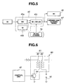
- Fig. 4 is a functional block diagram of the engine control unit.
- Fig. 6 is a circuit diagram of a spark plug drive circuit employed in the embodiment according to the present invention.
- Fig. 7 is a graph showing a relationship between an accelerator depression quantity and a required intake-air quantity.
- Fig. 8 is a time chart showing a response characteristic of a valve operated by an electromagnetic actuator.
- Fig. 11 is a time chart showing operating conditions of main parts in every stroke under an intake valve abnormal condition caused at the transition from the closing condition to the opening condition.
- Fig. 13 is a time chart showing operating conditions of main parts in every stroke under an exhaust valve abnormal condition caused at the transition from the opening condition to the closing condition.
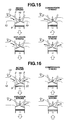
- Fig. 15 is a view showing operating conditions of a cylinder having an abnormal intake valve in every stroke when no treatment is executed to the abnormality.
- Fig. 21 is a graph showing an output characteristic of an airflow meter under a normal condition and an intake valve abnormal condition.
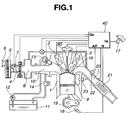
- a control unit 40 is connected to airflow meter 7, a temperature sensor 23 provided to cylinder 9, an air-fuel ratio sensor 22 provided to exhaust passage 20, a crank angle sensor 19 for detecting a rotation speed of a crankshaft 19, and an accelerator depression quantity sensor 17 for detecting a depression quantity of an accelerator pedal and receives signals from these sensors 7, 23, 22, 19 and 17 as information for controlling engine 1.
- Accessory target intake air quantity calculating section 45b calculates a demanded intake-air quantity necessary for maintaining the engine rotation speed at a target rotation speed under an idling condition, a demand intake-air quantity for driving accessories including an air conditioner, a generator, an oil pump for a power steering and so on, an intake-air quantity for a cruise control apparatus, and a negative intake-air quantity generated by a traction control.
- Response correcting sections 48 and 58 correct valve opening and closing timings according to the response characteristics of intake valve 2 and exhaust valve 3, respectively. That is, the intake and exhaust valves 2 and 3 generate dead time and delay time with respect to opening and closing commands to coils 31 and 32. Further, the valve response characteristics vary according to the circumstances of intake and exhaust valves 2 and 3. Response correcting section 48 and 58 estimate the valve circumstances and determine the output timing of the opening and closing coil commands so as to bring the actual opening and closing valve timing closer to desired timings, respectively.
- the gas in cylinder 9 is moved to the exhaust port according to the lift-up of the piston. As is similar to the case of Fig. 15, the combustion in cylinder 9 was not normal. Therefore, the gas including oxygen and fuel flows to exhaust passage 20 through the exhaust port. The oxygen and fuel reach catalyst 21 and react with catalyst 21. This reaction generates heat and may degrade catalyst 21.
- valve abnormality detecting section 61 detects abnormality of output value L detected by lift quantity sensor 34 of intake valve 2 of the specific cylinder. Valve abnormality detecting section 61 quickly informs the abnormality of intake valve 2 of the specific cylinder to fuel injection stop commanding section 65, normal valve closing commanding sections 62 and 72, current-flowing stop commanding section 75, ignition delay commanding section 76. Fuel injection stop commanding section 65 stops fuel injection of injector 13 of the specific cylinder through fuel injection quantity cylinder distributing section 44. Normal valve close commanding section 72 for exhaust valve 3 commands exhaust valve 3 of the specific cylinder to maintain the closing condition.
- the engine system according to the present invention is arranged so that ignition coil 16 is not ignited when the current-flowing to primary ignition coil 82 is not started and even when either of intake valve 2 or exhaust valve 3 is put into the abnormal condition at the transition of combustion cycle. Therefore, parts in intake passage 10 or parts in exhaust passage 20 are protected from being degraded by backfire or after-burn. Further, even when the current-flowing to primary ignition coil 82 has started during the transition process of either intake valve 2 or exhaust valve 3, the ignition of spark plug 16 is executed at the timing that the fuel density is minimum. This suppresses the damage to parts of intake passage 10 or exhaust passage 20 at minimum.
- the work quantity of the engine is an integral of pressure characteristic.
- the negative work executed by a conventional camshaft type engine is greater than that of the electromagnetically operated valve employed engine.
- the pressure characteristic curve during the intake stroke is shown by a broken line in Fig. 19. That is, pumping loss of the engine is decreased by optimizing the valve closing timing of intake valve through the operation of the electromagnetically operated valve. Therefore, the electromagnetically operated valve employed engine improves the fuel consumption during the intake stroke as compared with the conventional intake stroke. This is one of advantages of the electromagnetic operated valve equipped engine.
- Fig. 20 shows the behavior of cylinder pressure during the abnormal condition of intake and exhaust valves 2 and 3.
- intake valve 2 the gas repeatedly moves between the intake port and the cylinder.
- exhaust valve 3 the gas repeatedly moves between the exhaust passage and the cylinder.
- the cylinder pressure repeatedly deviates from the center of the pressure under the valve opening condition with a hysteresis due to the flow resistance of valve.
- the specific cylinder put in the abnormal condition generates no static gas-flow at the intake passage and the exhaust passage.
- the microscopic movement of gas between cycles is only caused. That is, the specific cylinder put in the abnormal condition may be eliminated from the total operation of the engine in view of the intake and exhaust operation of the gas. Therefore, it is preferable that the engine control under the abnormal condition is differentiated from that under the normal condition.
- the engine control system according to the present invention is arranged to generate an engine output under the normal condition even if one of four cylinders is put in the abnormal condition and is eliminated from the substantial operation.
- the engine control system may be arranged so that the driver can sense the engine is put in the abnormal condition. That is, opening and closing timing change commanding section 64 does not command intake-valve opening and closing timing calculating section 47 specifically so that the engine output is lowered to 3/4 times of the output under the normal condition by maintaining the intake air quantity per cylinder and the fuel injection quantity per cylinder.
- opening and closing timing change commanding section 64 does not command intake-valve opening and closing timing calculating section 47 specifically so that the engine output is lowered to 3/4 times of the output under the normal condition by maintaining the intake air quantity per cylinder and the fuel injection quantity per cylinder.
- an idling target intake-air quantity changing section 79 of control unit 40 commands target intake-air quantity calculating section 45 to increase the target intake-air quantity during idling so that the engine speed during idling is increased.
- parameters corresponding to an engine output or throttle opening are required for the operation of an automatic transmission control apparatus, a vehicle attitude control system or a drive system equipped with an electric drive motor for a hybrid vehicle. Accordingly, when the engine system is put in an abnormal condition, the engine output is decreased by an output of the abnormal cylinder. Consequently, it is necessary to decrease the engine output valve outputted from the engine control unit or corresponding valves thereto by subtracting the output of the abnormal cylinder from the output of the normal condition engine.
- the intake air quantity measured by airflow meter 7 includes the pulsation flow which is caused by the abnormality of the intake valve 2 of the specific cylinder, as shown in Fig. 21.
- the control unit 40 comprises an intake air quantity correcting section 68 which operates in reply to the command from the valve abnormality detecting section 61, when intake valve 2 is put in the abnormal condition.
- Intake air quantity correcting section 68 processes the output signals of airflow meter 7 for a predetermined time period by means of the weighted average process using a relatively large time-constant.
- This time-constant may be determined from an output characteristic of airflow meter 7 during the abnormal condition of intake valve at a specific cylinder. In this case, such an output characteristic has been previously obtained by experiments.
- the time-constant may be theoretically determined taking account of the measurement principle and responsibility of the airflow meter and the shape of the intake passage.
- A/F sensor 22 is disposed at the collector portion of the exhaust ports of cylinders 9 so as to receive the exhaust gases of the respective cylinders 9 sequentially when the engine operates normally. That is, the control unit 40 is arranged to detect the property of the exhaust gas of the intended cylinder 9 by sampling the output of A/F sensor 22 synchronized with the crankshaft angle.
- control unit 40 decides whether or not the executed times of the initialization is greater than a fourth predetermined number.
- the routine jumps to an end block to terminate the present routine.
- the routine proceeds to step S108.
- control unit 40 decides that the valve now diagnosed is not good. Further, control unit 40 displays this abnormal condition and decides not to execute the initialization procedure. Then, the routine proceeds to the end block to terminate the present routine.
- control unit 40 decides that it is possible to execute the initialization process and therefore the routine proceeds to step S105 wherein the initialization execution flag is set.
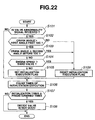
- the initialization execution flag is employed in the initialization execution routine based on the flowchart of Fig. 23.
- valve 2, 3 When the abnormality of valve 2, 3 is caused by the mechanical trouble, valve 2, 3 cannot return to the normal condition even by the execution of the initialization operation. Therefore, by the execution of the initialization execution flag setting process corresponding to step S105, the times of setting the initialization termination flag are counted at step S106 after the execution of the initialization execution process corresponding to steps S111 and S112.
- the abnormal condition of valve 2, 3 is returned to the normal condition by executing the initialization process once, and therefore the times of the executions of initialization is stayed at one.
- the abnormality of valve 2, 3 is not temporal due to the mechanical trouble, the abnormal condition is not returned to the normal condition.
- the detection method for detecting the abnormality of the valve 2, 3 may not be limited to this method and may employ other method, such as a method for detecting the abnormality from the vibration of the valve operation or a method for detecting the abnormality from the electrical characteristic of the objective coil.
- the ignition of the spark plug is stopped under the condition that the current-flowing to the primary ignition coil is not started. Therefore, the combustion in the combustion chamber, in the intake passage and in the exhaust passage is avoided. This avoidance prevents engine parts including the catalyst from being degraded by backfire or after-burn. Further, when the abnormality of the valve is generated and even when the ignition of the spark plug has been started, the ignition of the spark plug is executed at the time that the density of fuel in the specific cylinder including the abnormal valve becomes minimum. Therefore, the combustion in the combustion chamber becomes very soft so as to suppress the damages to various parts at minimum.
Landscapes
- Engineering & Computer Science (AREA)
- Mechanical Engineering (AREA)
- General Engineering & Computer Science (AREA)
- Output Control And Ontrol Of Special Type Engine (AREA)
- Electrical Control Of Air Or Fuel Supplied To Internal-Combustion Engine (AREA)
- Valve Device For Special Equipments (AREA)
- Ignition Installations For Internal Combustion Engines (AREA)
- Electrical Control Of Ignition Timing (AREA)
- Combined Controls Of Internal Combustion Engines (AREA)
Abstract
Description
Claims (22)
- An engine system comprising:electromagnetically operated intake and exhaust valves;a spark plug;a primary ignition coil;a secondary ignition coil generating an induction voltage according to a current-stopping operation to said primary ignition coil following a current-flowing operation, said secondary ignition coil outputting the induction voltage to said spark plug; anda control unit arrangedto decide whether each of intake and exhaust valves is put in an abnormal condition,to close a normal valve of said intake and exhaust valves when one of said intake and exhaust valves is put in the abnormal condition, andto stop the current-flowing to said primary ignition coil when one of said intake and exhaust valves is put in the abnormal condition and when the primary ignition coil does not start the current-following operation.
- The engine system as claimed in claim 1, wherein said control unit is arranged to delay the current-stopping operation when one of said intake and exhaust valves is put in the abnormal condition and when the primary ignition coil has started the current-flowing operation, and to execute the current-stopping operation when a combustion chamber volume becomes larger than that at a normal ignition.
- The engine system as claimed in claim 1, further comprising a fuel injector, wherein said control unit is arranged to stop the fuel injection of said fuel injector when one of said intake and exhaust valves is put in the abnormal condition.
- The engine system as claimed in claim 1, wherein each of said intake and exhaust valves comprises a valve body, an opening electromagnetic coil for moving the valve body toward an opening direction, a closing electromagnetic coil for moving the valve body, a movable member attracted to the opening and closing electromagnetic coils, and a pair of coil springs for biasing the movable member at a neutral position between the opening and closing electromagnetic coils.
- The engine system as claimed in claim 1, further comprising a lift sensor installed to each of said intake and exhaust valves, said lift sensor detecting a lift quantity of a valve body of each of said intake and exhaust valves, wherein said control unit decides the abnormality of each of said intake and exhaust valves on the basis of a lift quantity indicative signal of the lift sensor.
- The engine system as claimed in claim 1, wherein said control unit closes said exhaust valve when said intake valve is put in the abnormal condition.
- The engine system as claimed in claim 1, wherein said control unit closes said intake valve when said exhaust valve is put in the abnormal condition.
- The engine system as claimed in claim 3, wherein when said control unit decides that said intake valve at a transition from a closing condition to an opening condition is abnormal, said control unit maintains a closing condition of said exhaust valve, stops the fuel injection of the fuel injector, and stops the current-flowing operation during intake stroke.
- The engine system as claimed in claim 3, wherein when said control unit decides that said intake valve at a transition from an opening condition to a closing condition during a first half of compression stroke is abnormal, said control unit maintains a closing condition of said exhaust valve, stops the fuel injection of the fuel injector, elongates the current-flowing operation and executes the current-stopping operation during a second half of explosion stroke.
- The engine system as claimed in claim 3, wherein when said control unit decides that the exhaust valve at a transition from an opening condition to a closing condition is abnormal, said control unit sets said intake valve at a closing condition, stops the fuel injection to the fuel injector, and stops the current-flowing to the primary ignition coil during intake stroke.
- The engine system as claimed in claim 3, wherein when said control unit decides that exhaust valve at a transition from a closing condition to an opening condition at an end of explosion stroke is abnormal, said control unit maintains said intake valve at a closing condition, stops the fuel injection of the fuel injector, and stops the current-flowing operation.
- An engine control system for an engine system, the engine system having a plurality of cylinders, each cylinder being equipped with electromagnetically operated intake and exhaust valves, a spark plug, a spark-plug drive circuit and a fuel injector, the spark-plug drive circuit including a primary ignition coil and a secondary ignition coil generating an induction voltage according to a current-stopping operation to the primary ignition coil following a current-flowing operation, the secondary ignition coil outputting the induction voltage to the spark plug, said engine control system comprising:
a control unit arrangedto decide whether each of intake and exhaust valves is put in an abnormal condition,to close a normal valve of the intake and exhaust valves of a cylinder when one of the intake and exhaust valves of the cylinder is put in the abnormal condition,to stop the current-flowing operation at the cylinder when one of the intake and exhaust valves of the cylinder is put in the abnormal condition and when the primary ignition coil for the cylinder does not start the current-flowing operation, andto stop the fuel injection of the fuel injector of the cylinder when one of the intake and exhaust valves of the cylinder is put in the abnormal condition. - The engine control system as claimed in claim 12, wherein said control unit is arranged to delay the current-stopping operation of the cylinder when one of the intake and exhaust valves of the cylinder is put in the abnormal condition and when the primary ignition coil of the cylinder has started the current-flowing, and to execute the current-stopping operation when a combustion chamber volume becomes larger than a combustion chamber volume at a normal ignition.
- The engine control system as claimed in claim 12, wherein said control unit is arranged to calculate a target intake air quantity from an air quantity for obtaining an engine output according to at least an accelerator depression quantity, to calculate an opening and closing timing of each intake valve from the target intake air quantity, to control the intake valve so as to be opened and closed at the calculated opening and closing timing, to calculate a basic fuel injection quantity for each cylinder on the basis of an detected engine speed and an detected intake air quantity, to control the fuel injector so as to inject the basic fuel injection quantity, to calculate the opening and closing timing so as to supply the target intake air quantity to each of cylinders except for the cylinder including the abnormal valve when the valve of the cylinder is abnormal, and to calculate the basic fuel injection quantity for each cylinder on the precondition that the total intake air is supplied to the cylinders except for the cylinder including the abnormal valve when the valve of the cylinder is abnormal.
- The engine control system as claimed in claim 12, wherein said control unit is arranged to calculate a target intake air quantity from an air quantity for obtaining an engine output according to at least an accelerator depression quantity, to calculate an opening and closing timing of each intake valve from the target intake air quantity, to control the intake valve so as to be opened and closed at the calculated opening and closing timing, to calculate a basic fuel injection quantity for each cylinder on the basis of an engine speed and an intake air quantity, and to increase the target intake-air quantity during idling so that the engine speed during idling is increased.
- The engine control system as claimed in claim 12, wherein said control unit is arranged to calculate a basic fuel injection quantity for each cylinder on the basis of an engine speed and an intake air quantity, to obtain a fuel injection quantity of each cylinder by correcting the basic fuel injection quantity on the basis of an air-fuel ratio in exhaust gases, to control said fuel injector so as to inject the corrected fuel injection quantity, and to stop the correction of the basic fuel injection quantity when the exhaust valve of one of the cylinders is abnormal.
- The engine control system as claimed in claim 12, wherein when said control unit decides that the intake valve of one of the cylinders is abnormal, said control unit corrects a detected intake air quantity closer to an intake air quantity detected under a normal condition of all intake valves.
- The engine control system as claimed in claim 12, wherein when said control unit decides that one of the intake and exhaust valves is abnormal, said control unit executes a recovery operation of the abnormal valve.
- The engine control system as claimed in claim 18, wherein said control unit decides whether it is possible to execute the recovery operation, and said control unit executes the recovery operation when said control unit decides that it is possible to execute the recovery operation.
- An engine control system for an internal combustion engine, the engine being equipped with electromagnetically operated intake and exhaust valves, said engine control unit comprising:a spark plug unit installed to each cylinder of the engine;a valve operation detecting device installed to each of the intake and exhaust valves, said valve operation detecting device detecting motions of each of intake and exhaust valves; anda control unit connected to said spark plug unit and said valve operation detecting device, said control unit being arrangedto decide whether each of intake and exhaust valves is put in an abnormal condition, on the basis of a signal of said valve operation detecting device,to close a normal valve of the intake and exhaust valves of a cylinder when said control unit decides that one of the intake and exhaust valves of the cylinder is put in an abnormal condition, andto command said spark plug unit of the cylinder to stop an igniting operation in the cylinder when one of the intake and exhaust valves of the cylinder is put in the abnormal condition and when said spark plug unit of the cylinder does not start the igniting operation.
- An engine control system for an internal combustion engine which is equipped with electromagnetically operated intake and exhaust valves, a spark plug, a spark-plug drive circuit and a fuel injector, the spark-plug drive circuit including a primary ignition coil and a secondary ignition coil generating an induction voltage according to a current-stopping operation to the primary ignition coil following a current-flowing operation, the secondary ignition coil outputting the induction voltage to the spark plug, said engine control system comprising:valve abnormality detecting means for deciding whether each of intake and exhaust valves is put in an abnormal condition;normal valve closing means for closing a normal valve of the intake and exhaust valves when one of the intake and exhaust valves is abnormal; andcurrent-flowing stopping means for stopping the current-flowing to the primary ignition coil when one of the intake and exhaust valves is put in the abnormal condition and when the current-flowing is not started.
- Method for controlling an engine which is equipped with electromagnetically operated intake and exhaust valves, a spark plug, a spark-plug drive circuit and a fuel injector, the spark-plug drive circuit including a primary ignition coil and a secondary ignition coil generating an induction voltage according to current-flowing and current-stopping operations to the primary ignition coil, the secondary ignition coil outputting the induction voltage to the spark plug, said method comprising:deciding whether each of intake and exhaust valves is put in an abnormal condition;closing a normal valve of the intake and exhaust valves when one of the intake and exhaust valves is put in the abnormal condition; andstopping the current-flowing to the primary ignition coil when one of the intake and exhaust valves is put in the abnormal condition and when the current-flowing is not started.
Applications Claiming Priority (2)
| Application Number | Priority Date | Filing Date | Title |
|---|---|---|---|
| JP35763899A JP3803220B2 (en) | 1999-12-16 | 1999-12-16 | Engine system control device with electromagnetically driven intake and exhaust valves |
| JP35763899 | 1999-12-16 |
Publications (3)
| Publication Number | Publication Date |
|---|---|
| EP1111202A2 true EP1111202A2 (en) | 2001-06-27 |
| EP1111202A3 EP1111202A3 (en) | 2002-05-15 |
| EP1111202B1 EP1111202B1 (en) | 2005-11-09 |
Family
ID=18455149
Family Applications (1)
| Application Number | Title | Priority Date | Filing Date |
|---|---|---|---|
| EP00127469A Expired - Lifetime EP1111202B1 (en) | 1999-12-16 | 2000-12-14 | System and method for controlling engine equipped with electromagnetically operated engine valve |
Country Status (4)
| Country | Link |
|---|---|
| US (1) | US6401684B2 (en) |
| EP (1) | EP1111202B1 (en) |
| JP (1) | JP3803220B2 (en) |
| DE (1) | DE60023826T2 (en) |
Cited By (1)
| Publication number | Priority date | Publication date | Assignee | Title |
|---|---|---|---|---|
| EP1329619A4 (en) * | 2000-10-02 | 2004-11-17 | Mikuni Kogyo Kk | DEVICE FOR OPENING / CLOSING CONTROL OF A MOTOR SUCTION VALVE BY ELECTROMAGNETIC ACTUATOR |
Families Citing this family (53)
| Publication number | Priority date | Publication date | Assignee | Title |
|---|---|---|---|---|
| DE50000537D1 (en) * | 1999-04-21 | 2002-10-24 | Siemens Ag | CONTROL SYSTEM FOR AN INTERNAL COMBUSTION ENGINE WITH ELECTROMECHANICALLY ACTUATED GAS EXCHANGE VALVES |
| JP2002242719A (en) * | 2001-02-20 | 2002-08-28 | Honda Motor Co Ltd | Hybrid vehicle control device |
| JP2002256913A (en) * | 2001-02-28 | 2002-09-11 | Hitachi Ltd | Vehicle drive |
| JP3607246B2 (en) * | 2001-11-30 | 2005-01-05 | 本田技研工業株式会社 | Control device for hybrid vehicle |
| JP3481226B2 (en) * | 2001-12-12 | 2003-12-22 | 本田技研工業株式会社 | Abnormality detection method for hybrid vehicles |
| US6668773B2 (en) * | 2002-05-14 | 2003-12-30 | Caterpillar Inc | System and method for calibrating variable actuation system |
| JP4082197B2 (en) * | 2002-12-05 | 2008-04-30 | トヨタ自動車株式会社 | Valve drive system for internal combustion engine |
| JP4284399B2 (en) * | 2003-03-04 | 2009-06-24 | 本田技研工業株式会社 | Anti-vibration support device for engine |
| US7073488B2 (en) * | 2003-03-11 | 2006-07-11 | Caterpillar Inc. | Cylinder cutout strategy for engine stability |
| JP2004332660A (en) * | 2003-05-09 | 2004-11-25 | Honda Motor Co Ltd | Control device for variable cylinder internal combustion engine |
| US7031821B2 (en) * | 2004-03-19 | 2006-04-18 | Ford Global Technologies, Llc | Electromagnetic valve control in an internal combustion engine with an asymmetric exhaust system design |
| US7032581B2 (en) * | 2004-03-19 | 2006-04-25 | Ford Global Technologies, Llc | Engine air-fuel control for an engine with valves that may be deactivated |
| US7165391B2 (en) | 2004-03-19 | 2007-01-23 | Ford Global Technologies, Llc | Method to reduce engine emissions for an engine capable of multi-stroke operation and having a catalyst |
| US7559309B2 (en) * | 2004-03-19 | 2009-07-14 | Ford Global Technologies, Llc | Method to start electromechanical valves on an internal combustion engine |
| US7383820B2 (en) | 2004-03-19 | 2008-06-10 | Ford Global Technologies, Llc | Electromechanical valve timing during a start |
| US7055483B2 (en) * | 2004-03-19 | 2006-06-06 | Ford Global Technologies, Llc | Quick starting engine with electromechanical valves |
| US7128687B2 (en) * | 2004-03-19 | 2006-10-31 | Ford Global Technologies, Llc | Electromechanically actuated valve control for an internal combustion engine |
| US7066121B2 (en) * | 2004-03-19 | 2006-06-27 | Ford Global Technologies, Llc | Cylinder and valve mode control for an engine with valves that may be deactivated |
| US7021289B2 (en) | 2004-03-19 | 2006-04-04 | Ford Global Technology, Llc | Reducing engine emissions on an engine with electromechanical valves |
| US7140355B2 (en) * | 2004-03-19 | 2006-11-28 | Ford Global Technologies, Llc | Valve control to reduce modal frequencies that may cause vibration |
| US7079935B2 (en) * | 2004-03-19 | 2006-07-18 | Ford Global Technologies, Llc | Valve control for an engine with electromechanically actuated valves |
| US7240663B2 (en) * | 2004-03-19 | 2007-07-10 | Ford Global Technologies, Llc | Internal combustion engine shut-down for engine having adjustable valves |
| US7194993B2 (en) | 2004-03-19 | 2007-03-27 | Ford Global Technologies, Llc | Starting an engine with valves that may be deactivated |
| US6938598B1 (en) | 2004-03-19 | 2005-09-06 | Ford Global Technologies, Llc | Starting an engine with electromechanical valves |
| US7028650B2 (en) | 2004-03-19 | 2006-04-18 | Ford Global Technologies, Llc | Electromechanical valve operating conditions by control method |
| US7107946B2 (en) * | 2004-03-19 | 2006-09-19 | Ford Global Technologies, Llc | Electromechanically actuated valve control for an internal combustion engine |
| US7017539B2 (en) * | 2004-03-19 | 2006-03-28 | Ford Global Technologies Llc | Engine breathing in an engine with mechanical and electromechanical valves |
| US7063062B2 (en) * | 2004-03-19 | 2006-06-20 | Ford Global Technologies, Llc | Valve selection for an engine operating in a multi-stroke cylinder mode |
| US7107947B2 (en) * | 2004-03-19 | 2006-09-19 | Ford Global Technologies, Llc | Multi-stroke cylinder operation in an internal combustion engine |
| US7072758B2 (en) * | 2004-03-19 | 2006-07-04 | Ford Global Technologies, Llc | Method of torque control for an engine with valves that may be deactivated |
| US7032545B2 (en) | 2004-03-19 | 2006-04-25 | Ford Global Technologies, Llc | Multi-stroke cylinder operation in an internal combustion engine |
| US7555896B2 (en) * | 2004-03-19 | 2009-07-07 | Ford Global Technologies, Llc | Cylinder deactivation for an internal combustion engine |
| US7128043B2 (en) | 2004-03-19 | 2006-10-31 | Ford Global Technologies, Llc | Electromechanically actuated valve control based on a vehicle electrical system |
| JP2006057596A (en) * | 2004-08-23 | 2006-03-02 | Toyota Motor Corp | Evaporative fuel supply device |
| US7082934B2 (en) * | 2004-08-24 | 2006-08-01 | Ford Global Technologies, Llc | Controlling spark for an engine with controllable valves |
| US7204132B2 (en) * | 2005-04-28 | 2007-04-17 | Ford Global Technologies, Llc | Method for determining valve degradation |
| JP2006348826A (en) * | 2005-06-15 | 2006-12-28 | Yanmar Co Ltd | Fuel injection control device |
| DE112006002008B4 (en) | 2005-08-11 | 2022-07-07 | Avl List Gmbh | Method for raising the exhaust gas temperature in an internal combustion engine |
| US7506625B2 (en) * | 2006-03-31 | 2009-03-24 | Caterpillar Inc. | Method and apparatus for controlling engine valve timing |
| DE102006054182A1 (en) * | 2006-11-16 | 2008-05-21 | Robert Bosch Gmbh | Method and device for operating an internal combustion engine having a plurality of cylinder banks |
| US8209107B2 (en) * | 2008-01-23 | 2012-06-26 | Hamilton Sundstrand Corporation | Electric motor for fuel pump with improved shutdown features |
| US8428809B2 (en) * | 2008-02-11 | 2013-04-23 | GM Global Technology Operations LLC | Multi-step valve lift failure mode detection |
| JP4484088B2 (en) * | 2008-03-26 | 2010-06-16 | 三菱自動車工業株式会社 | Fuel injection control device for internal combustion engine |
| US7881856B2 (en) | 2008-04-03 | 2011-02-01 | Hitachi, Ltd. | Apparatus for and method of controlling fuel injection of engine |
| JP4738440B2 (en) * | 2008-05-22 | 2011-08-03 | 日立オートモティブシステムズ株式会社 | Engine fuel injection control device |
| JP4738432B2 (en) * | 2008-04-03 | 2011-08-03 | 日立オートモティブシステムズ株式会社 | Engine fuel injection control device |
| US7546827B1 (en) * | 2008-08-21 | 2009-06-16 | Ford Global Technologie, Llc | Methods for variable displacement engine diagnostics |
| JP5126104B2 (en) * | 2009-02-17 | 2013-01-23 | トヨタ自動車株式会社 | Deterioration judgment device for intake pressure sensor |
| JP6105868B2 (en) * | 2012-06-26 | 2017-03-29 | 株式会社不二工機 | Electric valve control device and electric valve device |
| US10234496B2 (en) * | 2016-02-16 | 2019-03-19 | Woodward, Inc. | Detection of valve open time for solenoid operated fuel injectors |
| US10619603B2 (en) * | 2017-08-22 | 2020-04-14 | Ford Global Technologies, Llc | Methods and systems for diagnosing engine internal exhaust gas recirculation |
| US10590879B2 (en) * | 2017-12-15 | 2020-03-17 | Ford Global Technologies, Llc | Variable displacement engine diagnostic method |
| FR3095079B1 (en) * | 2019-04-09 | 2021-07-30 | Commissariat Energie Atomique | Device for generating a gas |
Family Cites Families (4)
| Publication number | Priority date | Publication date | Assignee | Title |
|---|---|---|---|---|
| JPS63239367A (en) * | 1987-03-27 | 1988-10-05 | Hitachi Ltd | Ignition system for internal combustion engines |
| JP3683300B2 (en) * | 1995-01-27 | 2005-08-17 | 本田技研工業株式会社 | Control device for internal combustion engine |
| JP4080551B2 (en) * | 1995-01-27 | 2008-04-23 | 本田技研工業株式会社 | Control device for internal combustion engine |
| DE19733142C2 (en) * | 1997-07-31 | 2001-11-29 | Fev Motorentech Gmbh | Method for initiating the movement of a gas exchange valve actuated by an electromagnetic actuator |
-
1999
- 1999-12-16 JP JP35763899A patent/JP3803220B2/en not_active Expired - Fee Related
-
2000
- 2000-12-14 DE DE60023826T patent/DE60023826T2/en not_active Expired - Lifetime
- 2000-12-14 EP EP00127469A patent/EP1111202B1/en not_active Expired - Lifetime
- 2000-12-15 US US09/736,576 patent/US6401684B2/en not_active Expired - Fee Related
Cited By (2)
| Publication number | Priority date | Publication date | Assignee | Title |
|---|---|---|---|---|
| EP1329619A4 (en) * | 2000-10-02 | 2004-11-17 | Mikuni Kogyo Kk | DEVICE FOR OPENING / CLOSING CONTROL OF A MOTOR SUCTION VALVE BY ELECTROMAGNETIC ACTUATOR |
| US7011053B2 (en) | 2000-10-02 | 2006-03-14 | Mikuni Corporation | Controller for controlling opening and closing of an intake valve of an engine |
Also Published As
| Publication number | Publication date |
|---|---|
| EP1111202A3 (en) | 2002-05-15 |
| DE60023826T2 (en) | 2006-06-14 |
| JP3803220B2 (en) | 2006-08-02 |
| DE60023826D1 (en) | 2005-12-15 |
| EP1111202B1 (en) | 2005-11-09 |
| US20010003971A1 (en) | 2001-06-21 |
| US6401684B2 (en) | 2002-06-11 |
| JP2001173471A (en) | 2001-06-26 |
Similar Documents
| Publication | Publication Date | Title |
|---|---|---|
| US6401684B2 (en) | System for controlling engine equipped with electromagnetically operated engine valve | |
| US6640756B2 (en) | Electromagnetic valve controller of an internal combustion engine | |
| EP2020495B1 (en) | Engine equipped with adjustable valve timing mechanism | |
| US8141533B2 (en) | Control apparatus and method for internal combustion engine | |
| EP1106792B1 (en) | Control apparatus for internal combustion engines | |
| JP4306642B2 (en) | Internal combustion engine control system | |
| US7673608B2 (en) | Engine starting for engine having adjustable valve operation | |
| US7444999B2 (en) | Control system and method for internal combustion engine | |
| EP1770265A2 (en) | EGR control system for internal combustion engine | |
| US7051687B2 (en) | Valve operation controller | |
| CN108625996A (en) | method and system for engine control | |
| US8428854B2 (en) | Internal EGR control system for internal combustion engine | |
| US11313312B2 (en) | Engine control method and engine system | |
| CN100570132C (en) | engine control unit | |
| US11067008B2 (en) | Internal combustion engine control method and internal combustion engine control device | |
| JP2004068617A (en) | Control device for internal combustion engine | |
| JP2005226655A (en) | Control device for internal combustion engine | |
| US8430067B2 (en) | Engine starting for engine having adjustable valve operation | |
| US6505604B2 (en) | Ignition timing control apparatus for internal combustion engine | |
| JP2010024853A (en) | Control device for internal combustion engine | |
| JP5590297B2 (en) | Control device for internal combustion engine | |
| JP2001193504A (en) | Internal combustion engine having an electromagnetically driven valve | |
| JP2001182564A (en) | Internal combustion engine having an electromagnetically driven valve | |
| JP4464901B2 (en) | Control device for compression ignition internal combustion engine | |
| JP2023034784A (en) | Egr valve control device |
Legal Events
| Date | Code | Title | Description |
|---|---|---|---|
| PUAI | Public reference made under article 153(3) epc to a published international application that has entered the european phase |
Free format text: ORIGINAL CODE: 0009012 |
|
| 17P | Request for examination filed |
Effective date: 20001214 |
|
| AK | Designated contracting states |
Kind code of ref document: A2 Designated state(s): AT BE CH CY DE DK ES FI FR GB GR IE IT LI LU MC NL PT SE TR |
|
| AX | Request for extension of the european patent |
Free format text: AL;LT;LV;MK;RO;SI |
|
| PUAL | Search report despatched |
Free format text: ORIGINAL CODE: 0009013 |
|
| AK | Designated contracting states |
Kind code of ref document: A3 Designated state(s): AT BE CH CY DE DK ES FI FR GB GR IE IT LI LU MC NL PT SE TR |
|
| AX | Request for extension of the european patent |
Free format text: AL;LT;LV;MK;RO;SI |
|
| RIC1 | Information provided on ipc code assigned before grant |
Free format text: 7F 01L 9/04 A, 7F 02D 41/22 B |
|
| AKX | Designation fees paid |
Designated state(s): DE FR GB |
|
| 17Q | First examination report despatched |
Effective date: 20031106 |
|
| GRAP | Despatch of communication of intention to grant a patent |
Free format text: ORIGINAL CODE: EPIDOSNIGR1 |
|
| RTI1 | Title (correction) |
Free format text: SYSTEM AND METHOD FOR CONTROLLING ENGINE EQUIPPED WITH ELECTROMAGNETICALLY OPERATED ENGINE VALVE |
|
| GRAS | Grant fee paid |
Free format text: ORIGINAL CODE: EPIDOSNIGR3 |
|
| GRAA | (expected) grant |
Free format text: ORIGINAL CODE: 0009210 |
|
| AK | Designated contracting states |
Kind code of ref document: B1 Designated state(s): DE FR GB |
|
| REG | Reference to a national code |
Ref country code: GB Ref legal event code: FG4D |
|
| REF | Corresponds to: |
Ref document number: 60023826 Country of ref document: DE Date of ref document: 20051215 Kind code of ref document: P |
|
| ET | Fr: translation filed | ||
| PLBE | No opposition filed within time limit |
Free format text: ORIGINAL CODE: 0009261 |
|
| STAA | Information on the status of an ep patent application or granted ep patent |
Free format text: STATUS: NO OPPOSITION FILED WITHIN TIME LIMIT |
|
| 26N | No opposition filed |
Effective date: 20060810 |
|
| PGFP | Annual fee paid to national office [announced via postgrant information from national office to epo] |
Ref country code: FR Payment date: 20101224 Year of fee payment: 11 |
|
| PGFP | Annual fee paid to national office [announced via postgrant information from national office to epo] |
Ref country code: GB Payment date: 20101208 Year of fee payment: 11 |
|
| PGFP | Annual fee paid to national office [announced via postgrant information from national office to epo] |
Ref country code: DE Payment date: 20101208 Year of fee payment: 11 |
|
| GBPC | Gb: european patent ceased through non-payment of renewal fee |
Effective date: 20111214 |
|
| REG | Reference to a national code |
Ref country code: FR Ref legal event code: ST Effective date: 20120831 |
|
| REG | Reference to a national code |
Ref country code: DE Ref legal event code: R119 Ref document number: 60023826 Country of ref document: DE Effective date: 20120703 |
|
| PG25 | Lapsed in a contracting state [announced via postgrant information from national office to epo] |
Ref country code: DE Free format text: LAPSE BECAUSE OF NON-PAYMENT OF DUE FEES Effective date: 20120703 Ref country code: GB Free format text: LAPSE BECAUSE OF NON-PAYMENT OF DUE FEES Effective date: 20111214 |
|
| PG25 | Lapsed in a contracting state [announced via postgrant information from national office to epo] |
Ref country code: FR Free format text: LAPSE BECAUSE OF NON-PAYMENT OF DUE FEES Effective date: 20120102 |