EP1111161A2 - Elevator apparatus of seismic isolation building and non-seismic isolation building - Google Patents
Elevator apparatus of seismic isolation building and non-seismic isolation building Download PDFInfo
- Publication number
- EP1111161A2 EP1111161A2 EP00118907A EP00118907A EP1111161A2 EP 1111161 A2 EP1111161 A2 EP 1111161A2 EP 00118907 A EP00118907 A EP 00118907A EP 00118907 A EP00118907 A EP 00118907A EP 1111161 A2 EP1111161 A2 EP 1111161A2
- Authority
- EP
- European Patent Office
- Prior art keywords
- seismic isolation
- isolation building
- building
- hoisting road
- hoisting
- Prior art date
- Legal status (The legal status is an assumption and is not a legal conclusion. Google has not performed a legal analysis and makes no representation as to the accuracy of the status listed.)
- Granted
Links
Images













Classifications
-
- B—PERFORMING OPERATIONS; TRANSPORTING
- B66—HOISTING; LIFTING; HAULING
- B66B—ELEVATORS; ESCALATORS OR MOVING WALKWAYS
- B66B5/00—Applications of checking, fault-correcting, or safety devices in elevators
- B66B5/02—Applications of checking, fault-correcting, or safety devices in elevators responsive to abnormal operating conditions
- B66B5/021—Applications of checking, fault-correcting, or safety devices in elevators responsive to abnormal operating conditions the abnormal operating conditions being independent of the system
- B66B5/022—Applications of checking, fault-correcting, or safety devices in elevators responsive to abnormal operating conditions the abnormal operating conditions being independent of the system where the abnormal operating condition is caused by a natural event, e.g. earthquake
-
- E—FIXED CONSTRUCTIONS
- E04—BUILDING
- E04H—BUILDINGS OR LIKE STRUCTURES FOR PARTICULAR PURPOSES; SWIMMING OR SPLASH BATHS OR POOLS; MASTS; FENCING; TENTS OR CANOPIES, IN GENERAL
- E04H9/00—Buildings, groups of buildings or shelters adapted to withstand or provide protection against abnormal external influences, e.g. war-like action, earthquake or extreme climate
- E04H9/02—Buildings, groups of buildings or shelters adapted to withstand or provide protection against abnormal external influences, e.g. war-like action, earthquake or extreme climate withstanding earthquake or sinking of ground
- E04H9/021—Bearing, supporting or connecting constructions specially adapted for such buildings
Definitions
- the present invention relates to a elevator apparatus, and especially relates to an elevator apparatus which a car goes up and down a hoisting road internal which extends across a non-seismic isolation building and a seismic isolation building.
- an elevator which has a non-seismic isolation building having plural floor stories, a seismic isolation building having plural floor stories installed through a seismic isolation means on the non-seismic isolation building, a hoisting road for the elevator which is supported by the seismic isolation building and is extend to a top and bottom direction across the non-seismic isolation building and the seismic isolation building, a car to go back and forth on a hoisting road for this elevator to the top and bottom direction, a landing part of a lower hoisting road side of a hoisting road for the elevator, a non-seismic isolation building side entrance part provided on a non-seismic isolation building to face the hoisting road side landing part, and a expansion member provided at an entrance part of the non-seismic isolation building and at a position facing to the hoisting road side landing part and provided on a clearance to absorb earth quake motion so as to permit to relatively displace by earth qua
- an elevator has been proposed which has a non-seismic isolation building having plural floor stories, a seismic isolation building having plural floor stories installed through a seismic isolation means on the non-seismic isolation building, a hoisting road which is provided in a seismic isolation building and extends to a top and bottom direction, a car to go back and forth on the hoisting road to the top and bottom direction, a hoistway supporting frame work to connect a hoisting road formed in the non-seismic isolation building to a hoisting road formed in the seismic isolation building and to support a guide rail provided across the non-seismic isolation building and the seismic isolation building, a bound of a floor story door installed so as to displaced or incline according to a relative displacement between the non-seismic isolation building and the seismic isolation building, and a expansion member provided to face with the floor story door and handed across a clearance so as to permit to occur a displacement in the hoistway supporting frame
- an elevator apparatus having a hoisting road which is supported by the seismic isolation building and extend to a top and bottom direction, and a expansion floor which is handed to in a clearance between the seismic isolation building and the non-seismic isolation building in order to absorb earth quake motion
- an entrance part of the elevator facing the non-seismic isolation building is needed to be provided a expansion floor between the non-seismic isolation building side entrance part and a hoisting road side landing part, a big clearance is necessary for the entrance part facing the non-seismic isolation building.
- a hoistway supporting frame work to support a rail at the floor story of the seismic isolation building, and an abound of the floor story door installed in the hoistway supporting frame work, as there is a passage in the entrance part of the grade installing the hoistway supporting frame work, a big clearance is needed in the entrance part of the grade installing the hoistway supporting frame work.
- an object of the present invention is to make the clearance large that can be utilized as the entrance part of the non-seismic isolation building and the entrance part of the grade installing the hoistway supporting frame work.
- the present invention provides an elevator apparatus having a non-seismic isolation building having at least one story, a seismic isolation building installed through seismic isolation means on the non-seismic isolation building, a hoisting road structure being extended to a top and bottom direction in the non-seismic isolation building and the seismic isolation building and having a clearance for at least one of the non-seismic isolation building and the seismic isolation building so as to be able to relatively transfer / displace, a car that can move to the top and bottom direction along a hoisting road formed by the hoisting road structure, a hoisting road side landing part formed on the hoisting road structure, and a expansion floor provided at the clearance between an edge part of a floor of the non-seismic isolation building and a landing part of the hoisting road and making it possible to relatively transfer / displace by earth quake motion and to get on and off the car, the elevator apparatus characterized by comprising a movable wall provided between partition members which is located on
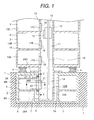
- Figure 1 is a drawing of a longitudinal section of the elevator apparatus showing one embodiment of the present invention.
- Figure 2 is a drawing of a longitudinal section of a non-seismic isolation building side entrance part of figure 1, and it shows a usual state when there is not a relative displacement between top and bottom buildings.
- Figure 3 is a drawing for explaining a state when the displacement outbreaks in front and back directions (pattern 1) in figure 2.
- Figure 4 is a drawing for explaining a state when the displacement outbreaks in front and back directions (pattern 2) in figure 2.
- Figure 5 is a sectional drawing viewed from a line I-I of figure 1, and it is a usually state when there is not a relative displacement between top and bottom buildings.
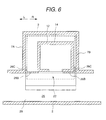
- Figure 6 is a sectional drawing viewed from a line I-I of figure 1, and it is a drawing for explaining a state when the displacement outbreaks in right and left directions (pattern 1).
- Figure 7 is a sectional drawing viewed from a line I-I of figure 1, and it is a drawing for explaining a state when the displacement outbreaks in right and left directions (pattern 2).
- Figure 8 is a sectional drawing viewed from a line I-I of figure 1, and it is a drawing for explaining a state when the displacement outbreaks in front and back directions (pattern 1).
- Figure 9 is a sectional drawing viewed from a line I-I of figure 1, and it is a drawing for explaining a state when the displacement outbreaks in front and back directions (pattern 1).
- Figure 10 is a sectional drawing viewed from a line II-II of figure 1.
- Figure 11 is a perspective drawing of the entrance part of the non-seismic isolation building side in a usual time in figure 1.
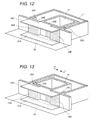
- Figure 12 is a perspective drawing of the entrance part of the non-seismic isolation building side to show a state when the displacement outbreaks in the right and left directions in figure 1.
- Figure 13 is a perspective drawing of the entrance part of the non-seismic isolation building side to show a state when the displacement outbreaks in the right and left directions in figure 1.
- Figure 14 is a perspective drawing of the entrance part of the non-seismic isolation building side to show a state when the displacement outbreaks in the front and back directions in figure 1.
- Figure 15 is a perspective drawing of the entrance part of the non-seismic isolation building side to show a state when the displacement outbreaks in the front and back directions in figure 1.
- Figure 16 is a side sectional drawing of the elevator apparatus showing an other embodiment of the present invention.
- Figure 17 is a detail drawing of a longitudinal section of the non-seismic isolation building side entrance part of the stories installed a hoistway supporting frame work of the elevator apparatus shown by figure 16, and it shows a usual state when there is not relative displacement between the top and the bottom buildings.
- Figure 18 is a drawing for explaining positional relationship when the displacement outbreaks in the front and the back directions (pattern 1) in figure 17.
- Figure 19 is a drawing for explaining positional relationship when the displacement outbreaks in the front and the back directions (pattern 2) in figure 17.
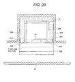
- Figure 20 is a sectional drawing viewed from a line I-I of figure 17, and it is a drawing for explaining a state when there is not relative displacement between the top and the bottom buildings.
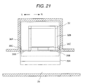
- Figure 21 is a drawing for explaining positional relationship when the displacement outbreaks in the right and the left directions (pattern 1) in figure 20.
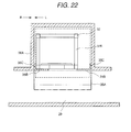
- Figure 22 is a drawing for explaining positional relationship when the displacement outbreaks in the right and the left directions (pattern 2) in figure 20.
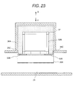
- Figure 23 is a drawing for explaining positional relationship when the displacement outbreaks in the front and the back directions (pattern 1) in figure 20.
- Figure 24 is a drawing for explaining positional relationship when the displacement outbreaks in the front and the back directions (pattern 2) in figure 20.
- Figure 25 is a sectional drawing viewed from a line II-II of figure 17, and it is a drawing for explaining a state in a usual time.
- Figure 26 is a drawing for explaining positional relationship when the displacement outbreaks in the right and the left directions (pattern 1) in figure 25.
- Figure 27 is a drawing for showing an other embodiment in the present invention.
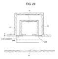
- Figure 28 is a drawing which shows a position relationship when the greatest displacement occurred in the front direction in figure 27.
- Figure 29 is a detailed perspective drawing of figure 27.
- Figure 30 is a perspective view for showing a state when the displacement in the front direction becomes the greatest figure 29.
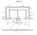
- Figure 31 is a sectional drawing for showing a constitution applied a present invention to a juxtaposition elevator.
- Figure 32 is a sectional drawing for showing a constitution applied a present invention to a juxtaposition elevator.
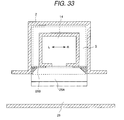
- Figure 33 is a sectional drawing for showing an other embodiment in the present invention.
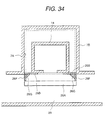
- Figure 34 is a sectional drawing for showing a state when a displacement in the front direction occurred figure 30.
- Figure 35 is a perspective drawing of figure 33.
- Figure 36 is a perspective drawing of figure 34.
- Figure 1 is a longitudinal sectional view of an elevator apparatus showing an embodiment of the present invention, and a building has a non-seismic isolation building 2 installed in ground 1 directly and a seismic isolation building 3 that is installed on an upper stories of the non-seismic isolation building 2.
- the seismic isolation building 3 is mounted on plural quake absorbing device 4 put on the non-seismic isolation building 2.
- the quake absorbing device 4 made with an elastic body being generally known exists between the non-seismic isolation building 2 and the seismic isolation building 3.
- the non-seismic isolation building 2 has a partition wall 7 provided in order to punctuate inside of a clearance surrounded with an outside wall 5 and a floor 6, and plural clearances 8A, 8B as chambers are had.
- a second floor story is shown as an example of the non-seismic isolation building 2, however, a floor story more than the second floor story may be used.
- the seismic isolation building 3 has an inside wall 12 forming an outside wall 9, a floor 10, and an upper stories hoisting road 11 of an elevator, and plural clearances 13A, 13B, 13C to be chambers.
- Upper stories hoisting road 11 extends longitudinally from a top story to a bottom story along the seismic isolation building 2, a car 15 of the elevator can go up and down in the upper stories hoisting road 11.
- a lower stories hoisting road 14 is arranged so as to move down in the non-seismic isolation building 2.
- This lower stories hoisting road 14 extends to a lower direction inside of a lower stories hoisting road structure 12B formed by a lower part partition wall 12A exceeding a seismic isolation device 4.
- This lower stories hoisting road structure 12B is located keeping a clearance in a room 7 provided inside of the non-seismic isolation building 2. This clearance absorbs an earth quake motion, and is needed to relatively transfer / displace the hoisting road structure 12B to the non-seismic isolation building 2.
- the elevator car 15 of the seismic isolation building 3 moves up and down inside of the hoisting road which is constituted by the lower stories hoisting road 14 and the upper stories hoisting road 11.
- the lower stories hoisting road structure 12B is formed with the seismic isolation building 3 as one body, and is formed by using a building material same as the seismic isolation building 3, however, the lower stories hoisting road structure 12B may be formed independently, and may be put together with the seismic isolation building 3 as one body by using a fixed means such as a bolt etc.
- the hoisting road structure which is formed by the upper stories hoisting road 11 and the lower stories hoisting road 14, is constituted by the walls 12A, 12.
- the lower stories hoisting road 14 is surrounded a circumference thereof with the lower partition wall 12A in the same way as the upper stories hoisting road 11, so that an outside person does not touch a car 15 to go up and down in the lower stories hoisting road 14.
- an extra protection means should be arranged so that the person does not touch the car 15.
- a building structure as that any person does not close to the upper stories hoisting road 11 or the lower stories hoisting road 14 should be planned.
- the car 15 of the elevator goes up and down in the upper stories hoisting road 11 and the lower stories hoisting road 14.
- a guide rail 16 to be extended to a vertical direction is provided, and the car 15 goes up and down along this guide rail 16.
- landing parts 17A, 17B, 17C for the elevator of the upper stories hoisting road 11 are provided respectively.
- the elevator landing parts 17A, 17B, 17C are arranged to go through the inside wall 12 of the hoisting road structure forming the upper stories hoisting road 11
- an entrance door 18 is arranged inside of the upper stories hoisting road 11. In stopping so as to correspond to the entrance door 18, a car door 19 is provided by car 15.
- the rooms 13A, 13B, 13C of the seismic isolation building 3 are adjacent to the upper stories hoisting road 11 through an inside wall 12.
- a partition wall 7 to form room 8A, 8B provided on the non-seismic isolation building 2 and the inside wall 12A to form the lower stories hoisting road 14, are provided separately so as to be displaced independently, the partition wall 7 and the inside wall 12A are arranged keeping a predetermined clearance S separately.
- the seismic isolation building 3 is installed through the seismic isolation device 4 on the upper part of the non-seismic isolation building 2,
- the hoisting road structure which constitutes lower stories hoisting road 14, is installed in the room 7 provided in the non-seismic isolation building 2 keeping the predetermined clearance S to the non-seismic isolation building 2.
- the seismic isolation building 3 and the non-seismic isolation building 2 are swung in an individual earth quake motion when the earthquake happens.
- clearance S to absorb the earth quake motion and to permit a relative displacement between the non-seismic isolation building 2 and the seismic isolation building 3 is needed between both.
- One part of hoisting road structure 12B extending to a top and bottom direction inside of the seismic isolation building 3 and the non-seismic isolation building 2 keeps a clearance S to the non-seismic isolation building 2, and a relative transfer / displacement becomes possible when earth quake motion outbreaks.
- the seismic isolation building 3 is swung with a same displacement from the top to the lower part of the whole building without bending the top of the building.
- an expansion floor 26A is installed between the non-seismic isolation building 2 and the elevator landing part 22 having the entrance door 21 for the person getting on and off the elevator.
- the hoisting road structure forming the upper stories hoisting road 11 and the lower stories hoisting road 14 is fixedly supported on the seismic isolation building 3 in figure 1, and the lower part of the hoisting road structure has a clearance S with the non-seismic isolation building 2, and however in the present invention, a reverse construction of such relation may be applied easily.
- the present invention is applied in the same way.
- the expansion floor 26A faces to an elevator landing part (a landing part) 22, and extends to right and left directions exceeding an edge part 141,142 of a width direction of the lower stories hoisting road 14 (a frontage direction) untill reaching the partition walls 7A, 7B, and closes the space between the inside wall 12A forming the lower stories hoisting road 14 of the front part of the elevator landing part 22 and the non-seismic isolation building 2. Accordingly, a passenger becomes possible to pass on the expansion floor.
- Length La of the expansion floor 26A is longer than width Lb of a landing side surface of the hoisting road structure 12B as shown in the figure, thereby a platform space can be taken broader.
- this expansion floor 26A is supported to the seismic isolation building 3 so as to be able to relatively move to front and back directions F, B for the non-seismic isolation building 2 and to be able to follow the partition walls 7A, 7B to right and left directions R, L.
- a dotted line P2 shows position of an edge of the floor of the non-seismic isolation building 2, and the expansion floor 26A is supported on the edge of the floor.
- the edge of the floor of the non-seismic isolation building 2 moves to the front direction till a position shown by an alternate long and short dash line P1 according to an earth quake motion.
- a lower stories hoisting road side of the expansion floor 26A facing the lower stories hoisting road is support by the lower stories hoisting road 14 so that the expansion floor 26A is capable to relatively move / displace to right and left directions against the lower stories hoisting road 14.
- a movable wall 26B of the building which extends to a top and bottom direction upto a ceiling is provided.
- This movable wall 26B of the building extends to the partition walls 7A, 7B to the right and left direction in the same way as the expansion floor 26A, and has a function to partition off an elevator landing 22 of the non-seismic isolation building 2 from the non-seismic isolation building 2 and the clearance between the non-seismic isolation building and the seismic isolation buildings.
- a movable side wall 26C mentioned later is provided in the partition walls 7A, 7B respectively provided in right and left side of this movable wall 26B.
- a slidable ceiling 26 opening to the partition walls 7A, 7B to the right and the left is provided in order to close clearance S same as the expansion floor 26A.
- a slidable ceiling 26 opening to the partition walls 7A, 7B to the right and the left is provided in order to close clearance S same as the expansion floor 26A.
- it may be provided in a bottom side of the story ceiling 28.
- a construction which the slidable ceiling 26 can prevents from hanging down should be provided.
- the expansion floor 26A, the movable wall 26B, and the slidable ceiling 26D may be separately supported in the lower stories hoisting road 14 respectively. In that case, to the right and left direction, they must be supported on the lower stories hoisting road.
- the expansion member 26 is formed with this expansion floor 26A, the movable wall 26B of the building and the slidable ceiling 26D, and it may be moved to the front and the back directions against the non-seismic isolation building 2 by using the partition walls 7A, 7B in the right and left directions as a guide. In addition, it may be moved to the right and left direction can be moved to against the lower stories hoisting road 14. When a relative displacement occurred between the non-seismic isolation building 2 and the seismic isolation building 3 by earthquakes, it can be possible to relatively transfer / displace to the right and left or the front and the back directions.
- the figure 10 shows details of the expansion floor 26A neighborhood, and is a sectional drawing along a line I-I of figure 1.
- the upper part and lower part guides 266, 268 sliding to the right and left direction by rolling on expansion member supporting brackets 262, 264, are fixed to the lower stories hoisting road 14 side, and the expansion floor 26A, the movable wall 26B, and the slidable ceiling 26D are supported by the upper part guide 266, and the lower part guide 268.
- the expansion floor 26A and the movable wall 26B slide to front and back directions against the lower stories hoisting road 14, and can move / displace relatively and freely.
- Figures 3, 8, 14 show a case that the building is displaced to a direction that the clearance S of platform part becomes bigger
- figures 4, 9, 15 show a case that the building is displaced to a direction that the clearance S of the platform part closes reversely
- Figures 6, 12, and figures 7, 13 show a case in which the non-seismic isolation building 2 relatively transfer / displace in the right and left direction against the seismic isolation building 3.
- Edge of the partition walls 7A, 7B located at right and left of the non-seismic isolation building 2, facing to the elevator hall 29, extends to the same surface with a surface of the movable wall 26B facing to the elevator hall 29 as shown in figure 5, however, when the expansion member 26 moves to a front side relatively to the non-seismic isolation building 2 by earthquakes, the movable wall 26B of the building exceeds the surface of the partition wall 7A, 7B in right and left facing to the elevator hall 29 as shown in figure 8.
- the edge of the movable wall 26B facing the partition wall 7A, 7B can be seen from the elevator hall side. Because, as thickness of the movable wall 26B of the building is small, it is blocked up with the movable side wall 26C (auxiliary member) which is in parallel with the partition walls 7A, 7B and extending to a reverse side against the elevator hall, and even if the relative displacement exceeds thickness of the movable wall 26B of the building, the clearance S can be partitioned off from the non-seismic isolation building 2.
- This movable side wall 26C works as a guide member to guide the movable wall 26B of the building to the front and back directions F, B along the partition walls 7A, 7B, and even if the movable wall 26B of the building moves to the front direction by an earth quake motion, the movable side wall 26C maintains to contact with the partition walls 7A, 7B and does not leave from it as shown in figure 8.
- the edge of the partition walls 7A, 7B located at right and left of the non-seismic isolation building 2, facing to the elevator hall 29, extends to the same surface with a surface of the movable wall 26B facing to the elevator hall, it may be extended to the position which does not exceeds the clearance which was provided between said non-seismic isolation building and the seismic isolation buildings.
- Movable wall 26B of the building moves back from an end surface of the partition wall 7A, 7B in the right and left sides facing the elevator hall, and when the relative displacement beween the seismic isolation building 3 and the non-seismic isolation building 2 becomes zero, the movable wall 26B of the building moves back to the same surface with the side surface of the partition wall 7A, 7B provided in the right and left sides facing the elevator hall 29.
- Figure 33, 34, 35 are views for showing other embodiment of the present invention
- a part member 26F extending to the elevator hall is provided in paralle to the partition walls 7A, 7B in both end parts of the movable wall 26B of the building, thereby the movable wall 26 is capable to move along the partition walls 7A, 7B.
- a reinforcement material 26F is provided to corners of the movable wall 26 and the part member 26F.
- the movable wall 26B of the building is provided to the back position beforehand so that the part member 26F do not move out, and when the earth quake motion breaks out, the part member 26F moves out as shown in figures 34, 36.
- this building in the present invention has a non-seismic isolation building 2 installed on ground 1 directly, and a seismic isolation building 3 installed on the non-seismic isolation building 2.
- the seismic isolation building 3 is mounted on plural seismic isolation devices 4 put on the non-seismic isolation building 2.
- the non-seismic isolation building 2 has partition walls 7 which partitions inside of the space surrounded with an outside wall 5 of the building and a floor 6, and plural spaces 8A, 8B, 8C as the rooms.
- the seismic isolation building 3 has inside walls 12 to form outside wall 9 of the building, floor 10, and upper stories hoisting road 11, and plural spaces 13A, 13B, 13C, 13D as the rooms.
- Hoisting road 30 of elevator is divided into a lower stories hoisting road 30A and an upper stories hoisting road 30B at an intermediate part of the building.
- a hoistway supporting frame work 32 is arranged across plural stories of non-seismic isolation building 2 and the seismic isolation building 3, a guide rail 31 is supported with this hoistway supporting frame work 32, and deformation of the guide rail 31 is dispersed into the several stories.
- This hoistway supporting frame work 32 is formed with a longitudinal frame 32A and a lateral beam 32B. The upper part of the hoistway supporting frame work 32 is supported on the seismic isolation building 3, and the lower part is supported on the non-seismic isolation building 2. As shown in figure 18 and figure 19, when this hoistway supporting frame work 32 inclines to front and back, and right and left directions, a relative displacement occurs between the non-seismic isolation building 2 and the seismic isolation building 3.
- the supporting frame work 34 to install the door 33 forgetting on and off the elevator is hanged.
- the supporting frame work 34 has construction to incline so as to follow the inclination.
- This hoistway supporting frame work 32 is possible to relatively displace for each building in any story of the non-seismic isolation building 2 side and the seismic isolation building 3 side.
- the clearance S2 is provided so as to permit the relative displacement between the hoistway supporting frame work 32 and each building of non-seismic isolation building 2 side or seismic isolation building 3 side.
- the expansion floor 35A is provided between the supporting frame work 34 that is a landing part of the elevator and the buildings so that a passenger gets it on and off.
- the expansion floor 35A is unnecessary.
- the clearance S2 of the stories installing the hoistway supporting frame work 32 is partitioned off from the buildings with partition walls 36A, 36B.
- the expansion floor 35A extends to the partition wall 36A, 36B provided in the right and left sides facing to the supporting frame work 34 and closes the clearance S2 in front of the supporting frame work 34.
- This expansion floor 35A is supported to the building to be able to move to the front and back directions of the entrance to the building.
- the supporting frame work 34 side of the expansion floor 35A is supported to the hoistway supporting frame work 32 to be able to move to right and left directions against the supporting frame work 34.
- the movable wall of the building 35B which extended to a top and bottom direction to a ceiling is provided on the supporting frame work 34 side of the expansion floor 35A.
- This movable wall of the building 35B extends to the partition wall 36A, 36B to the right and left directions in the same way as the expansion floor 35A, and it has a function to partition the clearance S2 from the elevator landing side of each building.
- a movable side wall 35C mentioned later is provided in a side surface of the movable wall 35B facing the partition walls 36A, 36B provided in the right and left directions. Movable wall of the building hip, 35B, is supported by a rotation pin 37A to incline so as to follow for a side of the supporting frame work 34 facing the elevator hall 29, and inclined to the front and back directions against the expansion floor 35A.
- This slidable ceiling 35D is supported with the rotation pin 37B so that the movable wall 35B can incline to the front and back directions in the same way as the expansion floor 35A.
- This expansion floor 35A, the slidable ceiling 35, and the movable wall 35B of the building may be supported on the supporting frame work 34 or the hoistway supporting frame war 32 each separately. However, in that case, to the right and left direction, it must be supported to be mobile for the supporting frame work 34 and the hoistway supporting frame work 32.
- the expansion member 35 is formed with this expansion floor 35A, the movable wall 35B and slidable ceiling 35D, and this expansion member 35 is movable to the front and the back directions against each building by using the partition walls 36A, 36B as a guide . In addition, it may be movable to the right and left directions against the supporting frame work 34 and the hoistway supporting frame work 32. When, a relative displacement occurred in the non-seismic isolation building 2 and the seismic isolation building 3 by earthquakes, it can be moved to the front and bck, and right and left directions.
- a side surface of the partition wall 36A, 36B in right and left of each building facing to the elevator hall 29 is arranged to be the same with a surface of the movable wall 35B facing the elevator hall 29, and when, the expansion member 35 moves to the front side against the each building by earthquakes, the movable wall 35B moves out to the front than a surface of the partition wall 36A, 36B facing to the elevator hall 29.
- the partition wall 36A, 36B side thereof can be seen from the elevator hall 29 side. Because, as the movable wall 35B of the building has not a sufficient thickness, the clearance S2 can be partitioned off each building by blocking up it with the movable side wall 35C even if the relative displacement exceeds a thickness of the movable wall 35B.
- the movable side wall 35C does a role of a guide when an expansion member swings to return. In addition, when the expansion member 35 moves to backward,
- the movable wall 35B of the building goes back to more than the surface of the partition wall 36A, 36B facing to the elevator hall 29, there becomes not to be a room for the relative displacement between the non-seismic isolation building 2 and the seismic isolation building 3, and the movable wall 35B of the building is sent back to the face same as the surface of the partition wall 36A, 36B facing to the elevator hall 29.
- the partition wall 36A, 36B facing to the elevator hall 29 may be arrnged to be out to the front direction always and previously referring to a moving amount that the movable wall of the building 35B moves out. In that case, the surface of movable wall 35B of the building facing to the partition wall 36A, 36B does not move out than the surface of the partition wall 36A, 36B facing to the elevator hall 29, and the movable side wall 35C needs not to be provided.
- the supporting frame work 34 is not supported on the hoistway supporting frame work 32, it can be applied in a construction which the supporting framework 34 links the hoistway supporting frame work 32 by using another mechanism.
- the elevator having the hoisting road which is provided in the seismic isolation building and extendss up and down, and a lower stories hoisting road structure which is put in a said non-seismic isolation building so as to be hung down from the lower part of the seismic isolation building, and has a lower stories hoisting road communicated to the hoisting road inside
- the partition wall of the entrance side is removed, and the movable wall of the building is provided in the lower stories hoisting road side
- a necessary space for the non-seismic isolation building side entrance part becomes to be only thickness of the movable wall of the building by partitioning off the clearance for an earth quake motion, it can be reduced than conventional one.
- a necessary space of the entrance part of the frame installation stories for supporting the rail becomes to be only for the thickness of the movable wall of the building, and can be reduced than that in conventional one, by removing the partition with the hoisting road of the entrance side so as to provide a movable wall of the building on a frame for supporting a rail, and to partition off the hoisting road.
- Figure 31 is a sectional drawing showing an other embodiment of the present invention, and a guide rail 31 is supported between hoisting road 30A, 39B of the non-seismic isolation building 2 and the seismic isolation building 3, and an elevator was added like in figure 16.
- a movable wall 35B of the building is installed in an entrance side of a lower stories hoisting road of the expansion floor 35A, and moves to front and back directions by using the partition wall 36A, 36B as a guide located in from side to side of said non-seismic isolation building.
- the elevator hall 29 is partitioned off a clearance S between the non-seismic isolation building 2 and the seismic isolation building 3.
- a movable wall 36H of the building may be provided on an expansion floor 35A of the entrance side of the lower stories hoisting road between the elevators.
- a central movable wall 35 H of the building and the expansion floor 35A can be moved to the front and back directions together, and the displacement by an earth quake motion of the building is absorbed, because it inclines.
- a side wall 39A is fixed on a rigid wall 40 of the building side.
- the side wall 39D is supported so as to be able to slide to top and bottom directions in the movable wall 35H of the building , and when the movable wall 35H of the building inclines, it is inclined so as to follow it.
- a notch part is provided so as not to hit the expansion floor 35A or the ceiling 35D.
- the side walls 39B, 39C have a construction which can be moved to a babkward (a depth direction) laterally, and the side wall 39C is moved to the movable wall side usually and the clearance of a notch under or over the side wall 39D is closed.
- a stopper 42 is arranged to each side wall, even if the movable wall 35H is displaced in the direction that the side wall spreads, the hole side and the space side become intercept.
- the side wall 39D Inclines too and the clearance of a notch of the lower part opens, however it is closed because there is the side wall 39C.
- the side wall 39C is caught on the stopper 42 of the side wall 39D, and it is pulled out from the side wall 39B.
- the side wall 39B is caught on the stopper 42 of the side wall 39C and is pulled out from said side wall 39A.
- the side wall 39C Inclines to a direction to be shortened on the contrary, the side wall 39C inclines, too, the clearance of the upper notch spreads, however it is closed because there is the side wall 39C.
- the side wall 39C hits the movable wall of the building 35H, is pushed into the side wall 39B side, and if being changed further, the side wall 39B hits the movable wall 35H, and is pushed into the side wall 39A.
- the elevator hall in the right and left side can be intercepted by closing the clearance between the rigid wall 40 and the wall of an other side of the hole 29 with the door or the shutter etc. 40.
- the clearance between the rigid wall 40 and the other side wall of the hole may be completely closed with the wall fixed to a building.
- it may be constituted with side walls of similar construction of plural pieces.
- the space for the elevator platform entrance can be provided larger.
Landscapes
- Engineering & Computer Science (AREA)
- Architecture (AREA)
- Environmental & Geological Engineering (AREA)
- Business, Economics & Management (AREA)
- Emergency Management (AREA)
- Structural Engineering (AREA)
- Civil Engineering (AREA)
- Life Sciences & Earth Sciences (AREA)
- General Life Sciences & Earth Sciences (AREA)
- Geology (AREA)
- Remote Sensing (AREA)
- Lift-Guide Devices, And Elevator Ropes And Cables (AREA)
- Maintenance And Inspection Apparatuses For Elevators (AREA)
- Buildings Adapted To Withstand Abnormal External Influences (AREA)
Abstract
Description
a movable wall provided between partition members which is located on both sides of the landing part of the non-seismic isolation building, is capable to relatively transfer / displace with the partition members when being swung in right and left directions relatively, being capable to relatively transfer / displace with the hoisting road structure when being swung in front and back directions, and being bigger than width of the landing part of the hoisting road structure.
when the relative displacement beween the
a
Claims (8)
- An elevator apparatus having a non-seismic isolation building (2) having at least one story,a seismic isolation building (3) installed through seismic isolation means (4) on said non-seismic isolation building (2),a hoisting road structure (12) being extended to a top and bottom direction in said non-seismic isolation building (2) and said seismic isolation building (3) and having a clearance (S) for said non-seismic isolation building so as to be able to relatively transfer/displace,a car (15) that moves to said top and bottom direction along a hoisting road (11, 14) formed by said hoisting road structure (12),a hoisting road side landing part (22) formed on said hoisting road structure (12), andan expansion floor (26A) provided at said clearance (S) between a landing part of said non-seismic isolation building (2) and said hoisting road landing part (22), said elevator apparatus characterised by comprisinga movable wall (26B) provided between partition members (7A, 7B) located on said non-seismic isolation building and said hoisting road structure (12),being capable to relatively transfer/displace with said partition members (7A, 7B) when said non-seismic isolation building (2) is swung in right and left directions, andbeing capable to relatively transfer/displace with said hoisting road structure (12) when said non-seismic isolation building (2) is swung in front and back directions.
- An elevator apparatus having a non-seismic isolation building (2) having at least one story,a seismic isolation building (3) having at least one story and an upper hoisting road (11) extending to a top and bottom direction and being installed through a seismic isolation means (4) on said non-seismic isolation building (2),a lower stories hoisting road structure (12B) having a lower stories hoisting road (14) which is supported by said seismic isolation building (3), is extended to said top and bottom direction in said non-seismic isolation building, and is communicated to said upper stories hoisting road (11),a car (15) that is movable to said top and bottom direction along said upper and lower stories hoisting roads (11, 14),a lower stories hoisting road side landing part (22) provided on said lower stories hoisting road structure (12B),a non-seismic isolation building side landing part installed on said non-seismic isolation building facing said lower stories hoisting road side landing part (22), andan expansion floor (26A) provided between said non-seismic isolation building (3) and said lower stories hoisting road side landing part (22), said elevator apparatus characterised by comprisinga movable wall (26B) being provided between partition members (7A, 7B) which is located on right and left sides of said landing part of said non-seismic isolation building, being capableto relatively transfer/displace with said partition members (7A, 7B) when non-seismic isolation building (2) is swung to right and left directions, andto relatively transfer/displace with said lower stories hoisting road structure (12B) when said non-seismic isolation building is swung in front and back directions.
- An elevator apparatus having a non-seismic isolation building (2) having at least one story,a seismic isolation building (3) having plural floor stories and an upper stories hoisting road (11) extending to a top and bottom direction and being installed through a seismic isolation means (4) on said non-seismic isolation building (2),a lower hoisting road which is installed on said non-seismic isolation building (2) and is connected to said upper stories hoisting road (11),a guide rail (31) which is provided across said non-seismic isolation building (2) and said seismic isolation building (3),a hoistway supporting frame work (32) which is provided across said non-seismic isolation building (2) and said seismic isolation building (3), anda bound for a floor story door installed in said hoistway supporting framework, said elevator apparatus characterised by comprisinga movable wall provided (35B) between partition members (36A, 36B) which are located on right and left sides of said landing part of said non-seismic isolation building or said seismic isolation building, being capableto move with said partition members when said non-seismic isolation (2) building is swung in right and left directions, andto relatively transfer/displace with said hoistway supporting frame work (32) when said lower stories hoisting road structure (30B) is swung in front and back directions.
- The elevator apparatus according to one of claims 1 to 3, wherein respective edges of said partition members facing an elevator hall are located to said back direction against said elevator hall from an edge of a floor of said non-seismic isolation building.
- The elevator apparatus according to one of claims 1 to 3, further comprising
an expansion floor which is movable to right and left and front and back directions with said movable wall, and extends to said partition members in said right and left sides. - The elevator apparatus according to one of claims 1 to 3, further comprising
a slidable ceiling which is movable to right and left and front and back directions with said movable wall, and blocks up said clearance extending to said partition members. - The elevator apparatus according to one of claims 1 to 3, whereinsaid movable wall is located in a position which retreated a predetermined distance from said elevator hall edge part of said partition members at a usual time when earth quake motion does not occur, andsaid movable wall does not stick out from said partition member even if the greatest earth quake motion occurs.
- The elevator apparatus according to one of claims 1 to 3, wherein said edge of said partition members of said movable wall extends in parallel to a direction within a face of said partition members.
Applications Claiming Priority (2)
| Application Number | Priority Date | Filing Date | Title |
|---|---|---|---|
| JP36338699A JP3523130B2 (en) | 1999-12-21 | 1999-12-21 | Elevator equipment |
| JP36338699 | 1999-12-21 |
Publications (3)
| Publication Number | Publication Date |
|---|---|
| EP1111161A2 true EP1111161A2 (en) | 2001-06-27 |
| EP1111161A3 EP1111161A3 (en) | 2003-05-14 |
| EP1111161B1 EP1111161B1 (en) | 2006-11-15 |
Family
ID=18479187
Family Applications (1)
| Application Number | Title | Priority Date | Filing Date |
|---|---|---|---|
| EP00118907A Expired - Lifetime EP1111161B1 (en) | 1999-12-21 | 2000-08-31 | Elevator apparatus of seismic isolation building and non-seismic isolation building |
Country Status (8)
| Country | Link |
|---|---|
| US (1) | US6557306B1 (en) |
| EP (1) | EP1111161B1 (en) |
| JP (1) | JP3523130B2 (en) |
| KR (1) | KR20010067132A (en) |
| CN (1) | CN1173876C (en) |
| DE (1) | DE60031830T2 (en) |
| SG (1) | SG85210A1 (en) |
| TW (1) | TW502000B (en) |
Families Citing this family (16)
| Publication number | Priority date | Publication date | Assignee | Title |
|---|---|---|---|---|
| US6860068B2 (en) * | 2001-06-26 | 2005-03-01 | John J. Halloran | Potential energy storage system |
| US7937471B2 (en) | 2002-06-03 | 2011-05-03 | Inpro Network Facility, Llc | Creating a public identity for an entity on a network |
| US8234358B2 (en) | 2002-08-30 | 2012-07-31 | Inpro Network Facility, Llc | Communicating with an entity inside a private network using an existing connection to initiate communication |
| US20040249974A1 (en) * | 2003-03-31 | 2004-12-09 | Alkhatib Hasan S. | Secure virtual address realm |
| US7949785B2 (en) | 2003-03-31 | 2011-05-24 | Inpro Network Facility, Llc | Secure virtual community network system |
| US20040249973A1 (en) * | 2003-03-31 | 2004-12-09 | Alkhatib Hasan S. | Group agent |
| JP2006213420A (en) * | 2005-02-01 | 2006-08-17 | Toshiba Elevator Co Ltd | Landing door installation structure of elevator for base-isolated building |
| JP5697872B2 (en) * | 2010-01-05 | 2015-04-08 | 株式会社竹中工務店 | Movement amount control device, structure |
| US8424253B2 (en) * | 2010-12-28 | 2013-04-23 | Ge-Hitachi Nuclear Energy Americas Llc | Seismic and impact mitigation devices and systems |
| JP2015113689A (en) * | 2013-12-16 | 2015-06-22 | 株式会社ドクター中松創研 | Building such as seismically isolated pilotis |
| CN107784917B (en) * | 2017-11-30 | 2023-06-30 | 重庆科技学院 | A Demonstration Device for Simulating Building Seismic Isolation |
| JP2019099325A (en) * | 2017-11-30 | 2019-06-24 | 株式会社日立製作所 | Elevator |
| CN109607343B (en) * | 2018-12-14 | 2023-09-26 | 华南理工大学 | An actual measurement device for elevator chimney effect in high-rise buildings |
| EP3865449B1 (en) * | 2020-02-12 | 2024-01-17 | KONE Corporation | Movable machine room, elevator arrangement and method for constructing elevator |
| JP7841912B2 (en) * | 2022-03-18 | 2026-04-07 | 清水建設株式会社 | Elevator seismic isolation structure |
| CN115142643B (en) * | 2022-06-29 | 2024-03-19 | 云南建投第六建设有限公司 | A kind of seismic isolation system suspended elevator shaft pouring structure and its construction method |
Family Cites Families (12)
| Publication number | Priority date | Publication date | Assignee | Title |
|---|---|---|---|---|
| US4766708A (en) * | 1985-12-27 | 1988-08-30 | Peter Sing | Shock and vibration resistant structures |
| JP2596610B2 (en) * | 1989-02-28 | 1997-04-02 | オーチス エレベータ カンパニー | Column vibration detector for elevator system driven by linear motor |
| US5502932A (en) * | 1992-02-05 | 1996-04-02 | Chinese Building Technology Services Corporation Limited | Method and device of earthquake resistant & energy reduction for high-rise structures |
| JP3494507B2 (en) * | 1995-06-14 | 2004-02-09 | 株式会社日立製作所 | Elevator pit structure of base-isolated building |
| JP3162017B2 (en) * | 1996-01-23 | 2001-04-25 | 株式会社日立製作所 | Elevator equipment |
| JP2852226B2 (en) * | 1996-01-23 | 1999-01-27 | 株式会社日立製作所 | Elevator equipment |
| JPH09278315A (en) * | 1996-04-18 | 1997-10-28 | Taisei Corp | Elevator in seismically isolated building |
| JP3648347B2 (en) * | 1996-07-22 | 2005-05-18 | 株式会社日立製作所 | Elevator hoistway for intermediate seismic isolation building |
| JP3866344B2 (en) * | 1996-12-05 | 2007-01-10 | 三菱電機株式会社 | Elevator device for seismic isolation building |
| JP3965636B2 (en) * | 1997-01-20 | 2007-08-29 | 大成建設株式会社 | Elevator equipment |
| US5984052A (en) * | 1997-09-17 | 1999-11-16 | Otis Elevator Company | Elevator with reduced counterweight |
| JPH11130359A (en) * | 1997-10-28 | 1999-05-18 | Taisei Corp | Seismic isolation elevator |
-
1999
- 1999-12-21 JP JP36338699A patent/JP3523130B2/en not_active Expired - Lifetime
-
2000
- 2000-08-24 SG SG200004828A patent/SG85210A1/en unknown
- 2000-08-28 US US09/648,615 patent/US6557306B1/en not_active Expired - Lifetime
- 2000-08-30 TW TW089117646A patent/TW502000B/en not_active IP Right Cessation
- 2000-08-30 KR KR1020000050781A patent/KR20010067132A/en not_active Withdrawn
- 2000-08-31 CN CNB00126978XA patent/CN1173876C/en not_active Expired - Fee Related
- 2000-08-31 EP EP00118907A patent/EP1111161B1/en not_active Expired - Lifetime
- 2000-08-31 DE DE60031830T patent/DE60031830T2/en not_active Expired - Lifetime
Also Published As
| Publication number | Publication date |
|---|---|
| CN1173876C (en) | 2004-11-03 |
| CN1300709A (en) | 2001-06-27 |
| US6557306B1 (en) | 2003-05-06 |
| DE60031830D1 (en) | 2006-12-28 |
| TW502000B (en) | 2002-09-11 |
| HK1035521A1 (en) | 2001-11-30 |
| JP3523130B2 (en) | 2004-04-26 |
| SG85210A1 (en) | 2001-12-19 |
| EP1111161A3 (en) | 2003-05-14 |
| JP2001171939A (en) | 2001-06-26 |
| EP1111161B1 (en) | 2006-11-15 |
| DE60031830T2 (en) | 2007-03-29 |
| KR20010067132A (en) | 2001-07-12 |
Similar Documents
| Publication | Publication Date | Title |
|---|---|---|
| EP1111161A2 (en) | Elevator apparatus of seismic isolation building and non-seismic isolation building | |
| JP4351110B2 (en) | Movable landing equipment for elevators for base-isolated buildings | |
| JP3472954B2 (en) | Passenger conveyor equipment | |
| KR900006909Y1 (en) | Parking garage | |
| JP2852226B2 (en) | Elevator equipment | |
| JP3162017B2 (en) | Elevator equipment | |
| JP4287984B2 (en) | Base-isolated building structure | |
| JP3742263B2 (en) | Elevator equipment | |
| JP4425689B2 (en) | Elevator device for seismic isolation building | |
| JP4099857B2 (en) | Elevator entrance / exit structure | |
| JP4249058B2 (en) | Movable landing equipment for elevators for base-isolated buildings | |
| JP7841912B2 (en) | Elevator seismic isolation structure | |
| JP4099858B2 (en) | Elevator entrance / exit structure | |
| JP7657482B1 (en) | Ceiling soundproofing device and soundproofing structure for joints | |
| JPH1129277A (en) | Seismically isolated building elevator | |
| JP3843253B2 (en) | Base device for elevator for seismic isolation building | |
| JP4460386B2 (en) | Floor expansion joint device | |
| JP4481068B2 (en) | Movable landing equipment for elevators for base-isolated buildings | |
| JP6982903B2 (en) | Middle floor seismic isolation structure | |
| HK1035521B (en) | Elevator apparatus of seismic isolation building and non-seismic isolation building | |
| JP2006240786A (en) | Hall device for elevator of base isolated building | |
| JP3884701B2 (en) | Base device for elevator for seismic isolation building | |
| JP4481071B2 (en) | Elevator device for seismic isolation building | |
| RU49866U1 (en) | MINE OF PANORAMIC HYDRAULIC LIFT | |
| JP2005298150A (en) | Movable landing device for elevator for base isolation building |
Legal Events
| Date | Code | Title | Description |
|---|---|---|---|
| PUAI | Public reference made under article 153(3) epc to a published international application that has entered the european phase |
Free format text: ORIGINAL CODE: 0009012 |
|
| AK | Designated contracting states |
Kind code of ref document: A2 Designated state(s): AT BE CH CY DE DK ES FI FR GB GR IE IT LI LU MC NL PT SE |
|
| AX | Request for extension of the european patent |
Free format text: AL;LT;LV;MK;RO;SI |
|
| PUAL | Search report despatched |
Free format text: ORIGINAL CODE: 0009013 |
|
| AK | Designated contracting states |
Designated state(s): AT BE CH CY DE DK ES FI FR GB GR IE IT LI LU MC NL PT SE |
|
| AX | Request for extension of the european patent |
Extension state: AL LT LV MK RO SI |
|
| 17P | Request for examination filed |
Effective date: 20031106 |
|
| AKX | Designation fees paid |
Designated state(s): DE FR |
|
| 17Q | First examination report despatched |
Effective date: 20040123 |
|
| GRAP | Despatch of communication of intention to grant a patent |
Free format text: ORIGINAL CODE: EPIDOSNIGR1 |
|
| RAP1 | Party data changed (applicant data changed or rights of an application transferred) |
Owner name: HITACHI, LTD. Owner name: HITACHI MITO ENGINEERING CO., LTD. |
|
| GRAS | Grant fee paid |
Free format text: ORIGINAL CODE: EPIDOSNIGR3 |
|
| GRAA | (expected) grant |
Free format text: ORIGINAL CODE: 0009210 |
|
| AK | Designated contracting states |
Kind code of ref document: B1 Designated state(s): DE FR |
|
| REF | Corresponds to: |
Ref document number: 60031830 Country of ref document: DE Date of ref document: 20061228 Kind code of ref document: P |
|
| EN | Fr: translation not filed | ||
| EN | Fr: translation not filed | ||
| PLBE | No opposition filed within time limit |
Free format text: ORIGINAL CODE: 0009261 |
|
| STAA | Information on the status of an ep patent application or granted ep patent |
Free format text: STATUS: NO OPPOSITION FILED WITHIN TIME LIMIT |
|
| 26N | No opposition filed |
Effective date: 20070817 |
|
| PG25 | Lapsed in a contracting state [announced via postgrant information from national office to epo] |
Ref country code: FR Free format text: LAPSE BECAUSE OF FAILURE TO SUBMIT A TRANSLATION OF THE DESCRIPTION OR TO PAY THE FEE WITHIN THE PRESCRIBED TIME-LIMIT Effective date: 20070629 |
|
| PG25 | Lapsed in a contracting state [announced via postgrant information from national office to epo] |
Ref country code: FR Free format text: LAPSE BECAUSE OF FAILURE TO SUBMIT A TRANSLATION OF THE DESCRIPTION OR TO PAY THE FEE WITHIN THE PRESCRIBED TIME-LIMIT Effective date: 20061115 |
|
| PGFP | Annual fee paid to national office [announced via postgrant information from national office to epo] |
Ref country code: DE Payment date: 20140827 Year of fee payment: 15 |
|
| REG | Reference to a national code |
Ref country code: DE Ref legal event code: R119 Ref document number: 60031830 Country of ref document: DE |
|
| PG25 | Lapsed in a contracting state [announced via postgrant information from national office to epo] |
Ref country code: DE Free format text: LAPSE BECAUSE OF NON-PAYMENT OF DUE FEES Effective date: 20160301 |