BACKGROUND OF THE INVENTION
1 Technical Field of the Invention
The present invention relates generally to an antiskid brake
system for automotive vehicles designed to control the brake force
applied to each wheel of the vehicle during deceleration thereof.
2 Background Art
Antiskid brake systems (ABSs) are well known as a brake
control system which controls the brake pressure during
deceleration of an automotive vehicle. The antiskid brake systems
work to control brake forces acting on wheels based on the fact
that an increase in slip ratio S will cause a rate of change in
coefficient of adhesion µ between tire and road (it is in effect the
coefficient of friction), as shown in Fig. 1(a), to change greatly
following a target slip ratio Sm (e.g., 10%). In practice, the
antiskid brake systems determine the timing where a brake
pressure (i.e., a brake fluid pressure) applied to each wheel is
increased or decreased, as shown in Fig. 1(b), based on the wheel
speed Vw and the wheel acceleration Vw' and regulate the brake
pressure acting on each wheel.
The wheel acceleration Vw**' of each wheel is usually
given by the equation (1) below.
I/rVw**' = Fmax - Kpad · Pb **
where the suffix "**" expresses FR, FL, RR, and RL standing for a
front right, a front left, a rear right, and a rear left wheel,
respectively, I is the moment of inertia of each wheel, r is the
radius of tire, Fmax is a maximum road-tire frictional force, Kpad
is a constant, and Pb**is a wheel cylinder pressure.
The product Kpad · Pb** represents the brake force. As
apparent from the equation (1), in a range 1, as shown in Fig. 1(a),
where the slip ratio is smaller, an increase in brake force will cause
the coefficient of friction to increase, so that the wheel acceleration
Vw**' hardly changes, but when the brake force exceeds the
maximum frictional force Fmax (i.e., in a range 2), it reflects
directly on the wheel acceleration Vw**'.
The antiskid brake systems usually determine the speed of
a vehicle body VB (referred to as a vehicle speed below) based on
the greatest of four wheel speeds and regulate the brake pressure
so as to bring a slip ratio, as determined by a difference between
the vehicle speed VB and the wheel speed Vw**, into agreement
with a target slip ratio (e.g., 10%) in which the brake force reaches
a peak thereof. For instance, when the difference between the
vehicle speed VB and the wheel speed Vw**is great, the antiskid
brake systems decrease the brake pressure.
Usually, a maximum deceleration of the vehicle when being
brought to rest depends upon the condition of a road surface. In a
case of a high friction road such as an asphalt road, a maximum of
1.0G is reached. The determination of whether the coefficient of
friction exceeds the peak or not must, therefore, wait until a higher
deceleration as much as 1.0G is reached. This, however, results
in an undesirable drop in wheel speed, leading to a great wheel
slippage.
It is difficult to derive the vehicle speed from speeds of four
wheels accurately. The slip ratio in which the coefficient of
friction reaches the peak depends upon the type of road surface.
It is, therefore, impossible to precisely determine the speed
producing the slip ratio in which the brake force reaches a
maximum value (i.e., a target speed). Specifically, a shift in the
target speed may result in a delay of the brake control, so that the
wheel speeds drop undesirably, thereby leading to a great wheel
slippage.
SUMMARY OF THE INVENTION
It is therefore a principal object of the invention to avoid the
disadvantages of the prior art.
It is another object of the invention to provide an antiskid
brake system capable of determining a wheel skid precisely without
using parameters such as vehicle speed and wheel speeds as
employed in conventional antiskid brake systems.
It is a further object of the invention to provide a brake
condition determining device capable of determining a braking
condition of a vehicle accurately.
According to one aspect of the invention, there is provided
an antiskid brake system for a vehicle. The system includes: (a) a
wheel speed determining circuit determining a speed of a wheel of
the vehicle; (b) a parameter determining circuit determining a
parameter reflecting on brake torque applied to the wheel of the
vehicle; (c) a braking condition determining circuit comparing a
phase of a change in speed of the wheel determined by the wheel
speed determining circuit with a phase of a change in parameter
determined by the parameter determining circuit to determine a
phase delay of the change in speed of the wheel and determining a
braking condition based on the phase delay; and (d) an antiskid
brake controlling circuit performing antiskid brake control based
on the braking condition determined by the braking condition
determining circuit.
In the preferred mode of the invention, the braking
condition determining circuit increases the parameter in the form
of a pulse and determines the braking condition the change in
speed of the wheel as a function of a step change in the parameter.
The braking condition determining circuit determines the
braking condition based on a fact that the phase of the change in
speed of the wheel is delayed from the phase of the change in
parameter determined by the parameter determining circuit as a
slip ratio increases.
The parameter determined by the parameter determining
circuit is a pressure of hydraulic fluid supplied cyclically to a wheel
cylinder of the vehicle in the form of a pulse. A cycle in which the
pressure of hydraulic fluid is supplied to the wheel cylinder is
lower than a cycle of resonant vibrations occurring at a suspension
system of the vehicle depending upon a type of the vehicle.
The wheel speed determining circuit provides a signal
indicative of the speed of the wheel to the braking condition
determining circuit. A frequency higher than a frequency of
resonant vibrations occurring in a suspension system of the vehicle
is removed from the signal indicative of the speed of the wheel.
The change in speed of the wheel is one of a first parameter
representing a difference between instant values of the speed of the
wheel sampled at a given time interval cyclically and a second
parameter representing a difference between instant values of the
first parameter sampled at the given time interval cyclically.
The change in speed of the wheel may alternatively be one
of a first parameter that is a first difference between instant values
of the speed of the wheel sampled at a given time interval cyclically
minus a mean value of the first differences sampled for a given
period of time and a second parameter that is a second difference
between instant values of the first parameter sampled at the given
time interval cyclically minus the second differences sampled for a
given period of time.
The change in parameter determined by the parameter
determining circuit is a change in pressure of hydraulic fluid
supplied to a wheel cylinder of the vehicle in a given period of time.
The change in parameter determined by the parameter
determining circuit may alternatively be the change in pressure of
hydraulic fluid supplied to a wheel cylinder of the vehicle in a given
period of time minus a means values of the changes in pressure of
the hydraulic fluid for a given period of time.
According to another aspect of the invention, there is
provided a braking condition determining device for a vehicle which
comprises: (a) a wheel speed determining circuit determining a
speed of a wheel of the vehicle; (b) a parameter determining circuit
determining a parameter reflecting on brake torque applied to the
wheel of the vehicle; and (c) a braking condition determining circuit
comparing a phase of a change in speed of the wheel determined
by the wheel speed determining circuit with a phase of a change in
parameter determined by the parameter determining circuit to
determine a phase delay of the change in speed of the wheel and
determining a braking condition of the wheel based on the phase
delay.
BRIEF DESPCRIPTION OF THE DRAWINGS
The present invention will be understood more fully from
the detailed description given hereinbelow and from the
accompanying drawings of the preferred embodiments of the
invention, which, however, should not be taken to limit the
invention to the specific embodiments but are for the purpose of
explanation and understanding only.
Fig. 1(a) shows a relation between the brake force and the
slip ratio in a conventional antiskid brake system; Fig. 1(b) shows changes in wheel speed, vehicle speed,
deceleration, and brake pressure under conventional antiskid
brake control; Fig. 2(a) shows a change in brake force in a conventional
antiskid brake control; Fig. 2(b) shows a change in wheel speed in a conventional
antiskid brake control; Fig. 2(c) shows a change in tire-road adhesion µ in a
conventional antiskid brake control; Fig. 3 shows changes in wheel speed Vw and acceleration
Vw' in a conventional antiskid brake control; Fig. 4 shows models expressing changes in brake force and
slip speed in ranges 1 and 2; Figs. 5(a) and 5(b) show a model representing a balance of
the slip speed Vs and brake force; Figs. 6(a) to 6(h) show relations between deformation of a
tire spring and a slippage of a road-contact surface of tire for
different damper factors of the tire; Figs. 7(a) to 7(h) show relations between a change in wheel
speed change and a change in wheel cylinder pressure for different
damper factors of tire; Fig. 8 shows a change in wheel speed Vw and changes in
pressure change ▵ Pb, wheel speed change ▵ Vw, and the wheel
speed change ▵ ▵ Vw when the wheel cylinder pressure Pb is
changed stepwise; Fig. 9 shows pressure-increasing patterns in ranges 1 and
2; Fig. 10 shows pressure-holding patterns in ranges 1 and 2; Fig. 11(a)and 11(b) show the degree of pressure increase in
a pressure-increasing pattern; Fig. 12 is a block diagram which shows an antiskid brake
system according to the invention; Fig. 13 is a block diagram which shows the structure of an
electronic control circuit of the antiskid brake system of Fig. 12; Fig. 14 is a view for explaining an operation of a phase
detector in the electronic control circuit of Fig. 13; Fig. 15 is a flowchart of an antiskid brake control operation; Fig 16 is a flowchart of a program for determining a target
wheel cylinder pressure in antiskid brake control; Fig. 17 is a flowchart of a program for controlling an
operation of a hydraulic servomechanism of the antiskid brake
system of Fig. 12; Fig. 18(a) shows wheel speed Vw, estimated W/C pressure
Pb, transfer gain, and phase delay ; Fig. 18(b) shows brake pressure change ▵ Pb and a change
in wheel speed change ▵ ▵ Vw; Fig. 18(c) shows the inverses in sign of brake pressure
change ▵ Pb and a change in wheel speed change ▵ ▵ Vw from
which offsets are removed; Fig. 19(a) is an enlarge view showing the
pressure-increasing pattern of Fig. 9; Figs. 19(b) and 19(c) show modifications of the
pressure-increasing pattern of Fig. 19(a); and Fig. 20 is a block diagram which shows a modification of
the electronic control circuit of Fig. 13.
DESCRIPTION OF THE PREFERRED EMBODIMENTS
Prior to describing preferred embodiments of the invention
in detail, a study made by the inventor of this application for
overcoming the problems, as discussed in the introductory part of
this application, will be discussed below.
First, changes in brake force, wheel speed, µ-s (road-tire
adhesion-slip ratio) characteristics were analyzed. When it is
required to increase the brake pressure supplied to a wheel
cylinder (also referred to below as W/C pressure), the typical
antiskid brake system steps up the W/C pressure. Changes in
brake force, wheel speed, and µ-s characteristics during the
increasing of the W/C pressure as measured are shown in Figs.
2(a) to 2(c), respectively.
As can be seen from Fig. 2(b), the wheel speed drops
suddenly in a range 2 in which the brake force has a peak. This is
because the brake torque overcomes the adhesion force between
tire and road, so that rubber blocks of a tire tread all commence to
slip. In a range 1 in which the brake force does not yet reach the
peak, so that the slip ratio is low, the wheel speed drops slightly.
Examples of changes in wheel speed Vw and wheel
acceleration Vw' with a change in W/C pressure Pb in the ranges 1
and 2 are shown in Fig. 3.
In the range 1, the adhesion between tire and road, that is,
the reaction force acting on the tire from the road changes with a
change in slip ratio. Thus, when the brake torque is increased,
the wheel speed Vw, as shown in Fig. 3, drops until the slip ratio is
reached which produces the adhesion matching the increased
brake torque. Specifically, the wheel speed Vw decreases stepwise
following a change in W/C pressure Pb.
In the range 2, the tire-road adhesion has reached an upper
limit thereof. The applied brake torque must, thus, be absorbed
by the force of inertia which is given, as shown in the above
equation (1), as a function of the wheel acceleration Vw'.
Therefore, the wheel speed Vw changes regardless of the wheel
cylinder pressure Pb. Only the rate of change in wheel speed Vw,
that is, the wheel acceleration Vw' changes.
Specifically, the step change in W/C pressure causes the
wheel speed Vw to change in the range 1 in which the slip ratio is
low and the wheel acceleration Vw' to change in the range 2 in
which the slip ratio is high. In other words, the phase of a change
in wheel speed Vw is shifted with the first-order lag following a
change in W/C pressure in the range 1, while the phase of a
change in wheel acceleration Vw' is shifted with the second-order
lag in the range 2.
Therefore, a change in wheel speed Vw with a step change
in brake force produced by a step change in W/C pressure may be
expressed in a model of Fig. 4. Specifically, the change in wheel
speed Vw may be modeled using a balance of a change ▵ Vs in slip
speed Vs caused by an increment ▵ TB of the brake force TB, a
spring factor Ct indicative of the stiffness of the tire, and a damper
factor given by dividing a rate Ck of change in frictional force
produced on a contact area of the tire with a road surface with a
change in slip speed Vs by the wheel speed Vw. Note that the slip
speed Vs is expressed by the sum of a speed difference Vs1
between tire tread and contact surface of the road and a speed
change Vs2 due to deformation of tire rubber and given by the
relation of Vs = Vs1 + Vs2. The slip speed Vs is thus equivalent
to a difference between the vehicle speed VB and the wheel speed
Vw, so that the phase of a change in slip speed Vs coincides with
the phase of a change in wheel speed Vw. The balance model in
Fig. 4 is defined using parameters of the slip speed Vs and the slip
speed change Δ Vs, however, the x-axis indicative of the slip speed
Vs may alternatively be a function of the slip ratio.
What is illustrated on the right side in each of the ranges 1
and 2 in Fig. 4 is a graph which represents the relation between
the slip speed Vs and the brake torque TB. A curve in the graph
indicates the slips speed change ▵ Vs as a function of a step change
▵ TB in brake torque TB. The spring factor Ct is, as clearly shown
in equation (2) below, a function of the sum of a coefficient Ccx
related to deformation of tread blocks of tire resulting from the
drag by the road surface, a coefficient Cb related to distortion of
the tire sidewalls causing an axis thereof to be shifted to a travel
direction, and distortion and deformation of various parts of tire
due to distortion of the tire side walls in rotational direction thereof
as expressed by a coefficient Cb. The value derived by
multiplying each term on the right side of the equation (2) by the
road-tire frictional force, thus, indicates a slip distance of the tire.
1/Ct = 1/Ccx + 1/Cb + 1/Cb
When the brake torque TB begins to increase, as shown in
the range 1, the dumper factor hardly changes (Ck ≒ ∞). Thus,
assuming that the effects of the force of inertia of the tire is ignored,
the slip speed Δ V changes stepwise by an amount, as specified by
the relation of Δ Vs = Δ TB/C, in synchronism with the brake
torque change Δ TB (see the left curve as illustrated below the graph
in the range 1 of Fig. 4). Specifically, in the model of Fig 4, the
wheel speed Vw is shifted in phase by the first-order lag following a
change in wheel cylinder pressure.
After the brake force is increased sufficiently, as shown in
the range 2, a change in the damper factor becomes great,
absorbing an increase in tire spring completely, so that only the
force of inertial acts on the wheel. If, therefore, the force of inertia
of the wheel is defined as J, we obtain J · Δ Vs' = Δ TB. The slip
speed change Δ Vs drops at a constant rate (see a curve as
illustrated below the graph in the range 2 of Fig. 4). Specifically,
in the model of Fig. 4, the wheel speed Vw is shifted in phase by
the second-order lag following a change in wheel cylinder pressure.
In a transitional period of time from the range 1 to the
range 2, the factor of the shift in phase of the wheel speed Vw
when the brake force TB is increased stepwise changes from the
first-order lag to the second-order lag gradually.
Figs. 5(a) and 5(b) show a model representing a balance of
the slip speed Vs and brake force.
Variations in slip speed Vs in the ranges 1 and 2 will be
discussed below in detail with reference to Figs. 5(a) and 5(b). In
the drawings, TB denotes the brake force (or brake torque). J
denotes the moment of inertia of tire. Ct denotes a total value of
various spring elements of tire (i.e., the stiffness). Vs denotes the
slip speed. Vs1 denotes a component of the slip speed Vs as
expressed as the amount of extension of the spring elements of tire.
Vs2 denotes a component of the slip speed Vs corresponding to the
amount of slippage of a road-contact surface of tire, that is, as
expressed as a shift in damper factor.
From the shown model, we obtain the following balance
equations.
J · Vw' = TB - Ct · Vs1
Ct · Vs1 = C/Vw · Vs2
Vs = Vs1 + Vs2 (= Vw - VB)
Specifically, the equation (3) represents a force balance in a
rotational direction of the tire. The equation (4) represents a force
balance of the spring elements of the tire and a road-contact
surface of the tire. The equation (5) indicates that the slip speed
is equivalent to the sum of the amount of extension of the spring
elements and the amount of slippage of the road-contact surface of
the tire.
Assuming that the brake torque
TB is increased by Δ
TB,
the change Δ
Vs in slip speed
Vs may be expressed using the above
equations as follows:
Note that the equation (6) is derived under condition that a
change in vehicle speed VB is much smaller than the slip speed
change Δ Vs so that it may be ignored.
From the equations (3) to (5), a change Δ
Vs1 in component
of the slip speed
Vs as expressed as the amount of extension of the
spring elements of the tire and a change Δ
Vs2 in component of the
slip speed
Vs as expressed as a shift in damper factor may be given
as
From the above equations, it is found that the change Δ Vs1
is shifted in phase by the first-order lag from the change Δ TB in
brake torque TB, and the change Δ Vs2 is shifted in phase by the
second-order lag from the change Δ TB in brake torque TB.
Specifically, in the range 1 where the damper factor hardly
changes, the slip speed Vs may be indicated as a function the
component Vs1 as expressed as the amount of extension of the
spring elements of the tire, and the change Δ Vs1 thereof is shifted
in phase by the first-order lag. In the range 2 where the damper
factor changes greatly, the slip speed Vs may be indicated as a
function the component Vs2 as expressed as the amount of shift in
damper factor, and the change Δ Vs2 thereof is shifted in phase by
the second-order lag.
Therefore, it is followed that the change in wheel speed Vw
which is substantially identical in phase with the slip speed Vs is
shifted in phase similar to the slip speed Vs.
For reference, results of simulations in terms of the speed
change Δ Vs1 resulting from the deformation of the tire spring when
a slippage factor of the road-contact surface of the tire (i.e., the
damper factor C) is decreased for a fixed spring constant of the tire
and the slip speed change ▵ Vs that is the sum of the speed change
▵ Vs1 and the amount of slippage of the road-contact surface of
the tire ▵ Vs2 are shown in Figs. 6(a) to 6(h). Results of
simulations in terms of the slip speed change ▵ Vs when the wheel
cylinder pressure Pb is changed stepwise are also shown in Figs.
7(a) to 7(h).
From the shown results, it is found that when the slippage
factor C is higher, only the tire spring is extended, changing the
slip speed change Δ Vs, and as the slippage factor C is decreased,
the change in extension of the tire spring is decreased, while the
amount of slippage of the road-contact surface of the tire is
increased.
Accordingly, the inventor of this application paid attention
to the phase delay of the slip speed change Δ Vs caused by the
brake torque change Δ TB and found a method of detecting a drop
in wheel speed Vw based on the phase delay of the slip speed
change Δ Vs to determine the timing where the brake pressure is
decreased in the antiskid brake control.
Fig. 8 shows a change in wheel speed Vw and resultant
changes in W/C pressure (referred to below as brake pressure
change Δ Pb, wheel speed Vw (referred to below as wheel speed
change Δ Vw, and wheel speed change Δ Vw (referred to below as
change in wheel speed change Δ Δ Vw, as determined in a given
period of time Δ T. A method of determining these parameters will
be described below in detail.
Comparison between the ranges 1 and 2 shows that the
waveforms of the wheel speed Vw, the wheel speed change Δ Vw,
and the change in wheel speed change Δ Δ Vw change, and phases
thereof are delayed.
The detection of drop in wheel speed Vw may, thus, be
accomplished using the fact that in a transitional period of time
from the range 1 to the range 2, the wheel speed Vw, the wheel
speed change Δ Vw, and the change in wheel speed change Δ Δ Vw
are shifted in phase thereof. For instance, when the phase delay
of the wheel speed Vw, that is, a shift in phase of the wheel speed
Vw from the W/C pressure Pb exceeds a given threshold value, it
may be determined that the wheel speed Vw has dropped.
It is difficult to compare the phase of the wheel cylinder
pressure Pb with the wheel speed Vw because null levels thereof
are different from each other. The comparison may, however, be
achieved by bringing null levels of the brake pressure change Δ Pb
and the wheel speed change Δ Vw into agreement with each other.
Therefore, the comparison between the phases of the brake
pressure change Δ Pb and the wheel speed change Δ Vw enables the
drop in wheel speed Vw to be detected based on the phase delay of
the wheel speed change Δ Vw.
The wheel speed change Δ Vw contains an offset equivalent
to the rate of decrease in vehicle speed (i.e., the deceleration of the
vehicle body), and, thus, the wheel speed change Δ Vw is not
expressed on the basis of the null level accurately. For this reason,
use of the change in wheel speed change Δ Vw allows the offset to
be removed from the wheel speed change Δ Vw, thereby allowing
the drop in wheel speed Vw to be determined accurately based on
the phase delay of the change in wheel speed change Δ Δ Vw
derived by comparing the phase of the brake pressure change Δ Pb
with that of the change Δ Δ Vw.
Next, the inventor of this application studied the
determination of the degree of drop in wheel speed Vw by
comparison between the phase of the brake pressure change Δ Pb
and the phase of the wheel speed change Δ Vw or the change in
wheel speed change Δ Δ Vw based on the above described analysis.
The phase delay of the wheel speed Vw is, as described
above, determined based on a step change in W/C pressure Pb.
Thus, the antiskid brake system measures, in practice, the phase
delay of the wheel speed Vw when the W/C pressure Pb is
increased, detects the drop in wheel speed Vw based on the phase
delay, and stops increasing the W/C pressure Pb and holds it
before the degree of drop in wheel speed Vw becomes great, that is,
before entering the range 2, thereby producing the brake force
whose level produces a value of the tire-road adhesion µ in the
vicinity of the peak thereof. This brake force will be referred to
below as a µ-peak brake force.
However, the road condition may be changed during
traveling of the vehicle. It is, thus, necessary to modify the W/C
pressure Pb quickly as a function of the change in road condition.
For instance, it is required to increase the W/C pressure Pb greatly
upon change in road condition. It is, thus, essential that a change
in drop in wheel speed Vw resulting from the change in road
condition be monitored during a time when the W/C pressure Pb is
held constant. It is, thus, advisable that a brake
pressure-increasing pattern and a brake pressure-holding pattern
used in the antiskid brake control be so determined that the
change in wheel speed Vw may be measured.
Accordingly, the inventor of this application found, as an
example, a brake pressure-increasing pattern and a brake
pressure-holding pattern, as shown in Figs. 9 and 10, suitable for
the antiskid brake control.
If a time (Δ T/2) that is half the change-determining cycle Δ
T is defined as the width of a pulse of brake pressure (i.e., a unit
change in W/C pressure), the W/C pressure Pb in the brake
pressure-increasing pattern of Fig. 9 is, in sequence, increased,
increased, held, and held during one control cycle equivalent to
four times the pulse width. In the brake pressure-holding pattern
of Fig. 10, the W/C pressure Pb is, in sequence, increased,
decreased, held, and held during one control cycle equivalent to
four times the pulse width. Specifically, a pulsed increase in W/C
pressure Pb is produced for measuring the degree of drop in wheel
speed Vw, after which the W/C pressure Pb is held at an initial
level.
As can be seen from Figs. 9 and 10, the brake pressure
change Δ Pb, the wheel speed change Δ Vw, and the change in wheel
speed change Δ Δ Vw in the brake pressure-increasing pattern
show waveforms similar to those in the brake pressure-holding
pattern. This allows the brake pressure change Δ Pb and the wheel
speed change Δ Vw or the change in wheel speed change Δ Δ Vw to
be compared in sequence in the brake pressure-increasing pattern
and the brake pressure-holding pattern.
Specifically, the use of the brake pressure-increasing and
-holding patterns allows the brake pressure change Δ Pb and the
wheel speed change Δ Vw or the change in wheel speed change Δ Δ
Vw to be compared even when the W/C pressure Pb is regulated
sequentially according to the brake pressure-increasing pattern
and the brake pressure-holding pattern, thus enabling a change in
wheel speed Vw to be determined even after start of regulation of
the W/C pressure Pb according the brake pressure-holding
pattern.
The use of a filter designed to calculate each of the brake
pressure change Δ Pb and the wheel speed change Δ Vw or the
change in wheel speed change Δ Δ Vw by finding a difference
between instant values sampled at a given time interval minimizes
a delay in determining the phases thereof. The
pressure-increasing and -holding patterns of Figs. 9 and 10, are so
made that the same change in W/C pressure Pb is repeated in
synchronism with the control cycle, thereby eliminating a variation
in calculating the phases between the control cycles.
When it is required to increase the W/C pressure quickly,
the amplitude of a rise in W/C pressure may be, as shown in Fig.
11(a), increased from the first control cycle to the second control
cycle. For instance, if a change in road surface condition is
detected in the pressure-holding mode, as shown in Fig. 11(b), by
monitoring the phase delay of a change in wheel speed Vw, the
need may arise for increasing W/C pressure rapidly upon the
change in road surface condition. In this case, it is preferable to
change the degree of a rise in W/C pressure like the one shown in
Fig. 11 (a).
Fig. 12 shows an antiskid brake system for automotive
vehicles according to the first embodiment of the invention.
The antiskid brake system has wheel speed sensors 5, 6, 7,
and 8 installed near front right, front left, rear right, and rear left
wheels 1, 2, 3, and 4, respectively. Each of the wheel speed
sensors 5 to 8 is made of an electromagnetic or an
magnetoresistance sensors and designed to output a pulse signal
whose frequency is a function of the number of rotations of a
corresponding one of the wheels 1 to 4 per unit time. The antiskid
brake system also includes hydraulic wheel cylinders (i.e., brakes)
11, 12, 13, and 14 to which the hydraulic pressure is supplied
from a master cylinder 16 through actuators 21, 22, 23, and 24
such as control valves to apply the brake pressure to the wheels 1
to 4, respectively.
The antiskid brake system also includes a stop switch 26
and an electronic control circuit 40. The stop switch 26 is
responsive to the depression of a brake pedal 25 initiating a
braking operation to output an ON-signal indicative thereof to the
electronic control circuit 40. When the brake pedal 25 is released,
the stop switch 26 outputs an OFF-signal to the electronic control
circuit 40.
The actuators 21 to 24 are electronically controlled by the
electronic control circuit 40 to regulate the pressure of brake fluid
in the wheel cylinders 11 to 14 under the antiskid brake control.
Each of the actuators 21 to 24 includes a three-position solenoid
valve designed to assume a pressure rise enable valve position A, a
pressure-holding valve position B, and a pressure-reducing valve
position C. The pressure rise enable valve position A is
established when each of the actuators 21 to 24 is deenergized to
communicate the master cylinder 16 with one of the wheel
cylinders 11 to 14, allowing the brake fluid pressure supplied to
the wheel cylinder (also referred to below as W/C pressure) to be
increased as a function of the pressure developed in the master
cylinder 16. The pressure-holding and pressure-reducing valve
positions B and C are established selectively as a function of the
level of current supplied to each of the actuators 21 to 24. In the
pressure-holding valve position B, the fluid communication
between the master cylinder 16 and each of the wheel cylinders 11
to 14 is blocked to hold the W/C pressure as is. In the
pressure-reducing valve position C, the brake fluid within each of
the wheel cylinders 11 to 14 is drained into one of reservoirs 28a
and 28b to reduce the W/C pressure. When the brake fluid within
the reservoirs 28a and 28b is filled up, each of motor-driven
pumps 27a and 27b pumps the brake fluid out of one of the
reservoirs 28a and 28b into the master cylinder 16.
The electronic control circuit 40 is implemented by a
microcomputer consisting of a CPU, a ROM, a RAM, and an
input/output interface and is activated upon turning on of an
ignition switch 41 to control the actuators 21 to 24 based on
signals from the wheel speed sensors 5 to 8 and the stop switch 26
according to an antiskid brake control program, as will be
described later in detail.
The electronic control circuit 40 has a control block, as
shown in Fig. 13, which consists of a peak search circuit 50, a
recovery circuit 60, and a hydraulic servomechanism 70. The
peak search circuit 50 and the recovery circuit 60 are actuated
selectively by a switch 71 as a function of a condition of the vehicle
so that a control signal produced by either of the peak search
circuit 50 and the recovery circuit 60 is inputted to the hydraulic
servomechanism 70. The hydraulic servomechanism 70
determines a pressure-increasing time in which the actuators 21 to
24 are actuated in a pressure-increasing mode, a pressure-holding
time in which the actuators 21 to 24 are actuated in a
pressure-holding mode, and a pressure-reducing time in which the
actuators 21 to 24 are actuated in a pressure-reducing mode and
also determines the W/C pressure Pb based on these times to
control drivers of the actuators 21 to 24. As will be described later
in detail, the switch 71 usually establishes a connection between
the peak search circuit 50 and the hydraulic servomechanism 70
and switches it to a connection between the recovery circuit 60 and
the hydraulic servomechanism 70 when a drop in wheel speed Vw
becomes great.
The peak search circuit 50 serves to control the W/C
pressure according to the pressure-increasing and
pressure-holding patterns, as shown in Figs. 9 and 10, so as to
apply the brake force to each of the wheels 1 to 4 which provides
the value of the tire-road adhesion µ near the peak thereof. The
peak search circuit 50 includes a hydraulic pressure change
determining circuit 51, a wheel speed change determining circuit
52, a phase detector 53, and a pressure-increasing/-holding
pattern selecting circuit 54. The hydraulic pressure change
determining circuit 51, as described later in detail, samples the
W/C pressure Pb derived by the hydraulic servomechanism 70
cyclically and determines, in sequence, a difference between an
instant value sampled currently and an instant value sampled a
given period of time earlier (i.e., the change-determining time
interval Δ T). This difference, as already discussed in Figs. 8, 9,
and 10, will be referred to below as brake pressure change Δ Pb.
The wheel speed change determining circuit 52 samples the signal
outputted from each of the wheel speed sensors 5 to 8 cyclically to
determine a difference between instant values of the wheel speed
Vw of each of wheels 1 to 4 in the same manner as the hydraulic
pressure change determining circuit 51. This difference will be
referred to below as wheel speed change Δ Vw. The phase detector
53, as will be described later in detail, determines a phase
difference between the brake pressure change Δ Pb and the wheel
speed change Δ Vw. The pressure-increasing/-holding pattern
selecting circuit 54 selects the pressure-increasing patter or the
pressure-reducing pattern based on the phase difference derived by
the phase detector 53. Upon selection of the pressure-increasing
or pressure-holding pattern, the pressure-increasing/-holding
pattern selecting circuit 54 compares the pattern with the W/C
pressure Pb and provides a hydraulic control signal PN to the
hydraulic servomechanism 70 through the switch 71 to have the
W/C pressure Pb follow the selected one of the pressure-increasing
and pressure-holding patterns under feedback control.
The recovery circuit 60 works to recover or compensate for a
drop in wheel speed Vw of each of the wheels 1 to 4 resulting from
an undesirable elevation in W/C pressure causing the tire-road
adhesion µ to exceed the peak which usually occurs when the
vehicle has moved to a low friction road from a high friction road or
when the vehicle is traveling on a road having different tire-road
adhesions µ. The recovery circuit 60 includes a maximum
frictional force equivalent pressure estimating circuit 61 and a
speed drop determining circuit 62. The maximum frictional force
equivalent pressure estimating circuit 61 estimates the brake
pressure PM required to produce a maximum frictional force
between road and tire that brings the road-tire adhesion µ to the
peak thereof. The speed drop determining circuit 62 determines
the amount of drop in wheel speed Vw (will also be referred to as
wheel speed drop WP) based on a change in wheel speed Vw. The
recovery circuit 60 produces the hydraulic control signal PN based
on the brake pressure PM and the wheel speed drop WP. When
the wheel speed drop WP exceeds a given threshold value, the
speed drop determining circuit 62 operates the switch 71 to
establish the connection between the recovery circuit 60 and the
hydraulic servomechanism 70 to output the hydraulic control
signal PN to the hydraulic servomechanism 70.
Fig. 14 shows a logical structure of the phase detector 53.
The phase detector 53 detects the phases of the brake
pressure change Δ Pb and the wheel speed change Δ Vw or the
change in wheel speed change Δ Δ Vw and determines a difference
in phase between the brake pressure change Δ Pb and the wheel
speed change Δ Vw or between the brake pressure change Δ Pb and
the change in wheel speed change Δ Δ Vw. The change in wheel
speed change Δ Δ Vw is, as already described, determined by
sampling the wheel speed change Δ Vw cyclically and determines,
in sequence, a difference between an instant value sampled
currently and an instant value sampled a given period of time
earlier (i.e., the change-determining time interval Δ T).
As will be described later in detail, in order to remove offsets
or noises contained in values of the brake pressure change Δ Pb
and the wheel speed change Δ Vw or the change in wheel speed
change Δ Δ Vw, the system of this embodiment subtracts a mean
value Mean(ΔPb) of a given number of successive values of the
brake pressure change Δ Pb, a mean value Mean(Δ Vw) of a given
number of successive values of the wheel speed change Δ Vw, and a
mean value Mean(Δ Δ Vw) of a given number of successive values
of the change in wheel speed change Δ Δ Vw from the brake
pressure change Δ Pb, the wheel speed change Δ Vw, and the
change in wheel speed change Δ Δ Vw, respectively, and outputs
resultant values to the phase detector 53.
For assuring the accuracy in determining the phase
difference in the phase detector 53, the change-determining time
interval ▵ T that is a time interval between sampled values used to
determine the brake pressure change ▵ Pb in the hydraulic
pressure change determining circuit 51 is set to coincide, in time
sequence, with that used in the wheel speed change determining
circuit 52. The pulse width Δ T/2 that is, as described above, the
width of a step change in W/C pressure and one control cycle of
each of the pressure-increasing and pressure-holding patterns are
fixed. In this embodiment, ▵ T = 0.1sec. The pulse width ▵ T/2
= 0.05sec. One control cycle of each of the pressure-increasing
and pressure-holding patterns = 0.2sec. The mean values
Mean(ΔPb), Mean(A Vw), and Mean(Δ Δ Vw) are determined
cyclically at a time interval T of 0.2sec.
The
phase detector 53 determines the phase difference
according to equations below.
y (t) = - ay ( t - 1 ) + bu ( t - 1) + e (t)
where a and b are constants, and e(t) represents an error
component.
Note that Eq. (9) represents a first-order lag model, Eq. (10)
represents model parameters, Eq. (11) represents a regression
vector, and Eq. (12) is a model parameter-projecting equation for
projecting the parameters in the model using the method of least
squares.
From the parameter derived by the equation (12), the phase
delay is determined. Eq. (13), as shown below, represents a
transfer function in fo (frequency). Eq. (14) is an equation for a
gain in fo. Eq. (15) is an equation for finding a phase delay in fo.
G = bZ -1 0 1 + aZ -1 0
where Z 0 =
e j 2 π foTs
mag = |G |
If an input/output time interval for the parameter
projection is increased further, we have
y (t) = - ay (t - m ) + bu (t - m ) + et
Note that Eq. (16) represents a modification of the
first-order lag model in Eq. 9, and Eq. (17) represents a regression
vector in the modified model in Eq. (16). By substituting Eq. (17)
into Eq. (12), a parameter is, similar to Eq. (12), obtained using the
method of least squares.
A case is referred to here which utilizes the identification of
a model based on the parameter derived in the method of least
squares, however, the methods of correlation, successive least
squares, and successive correlation may alternatively be used.
For reference, equations using the method of correlation are shown
below.
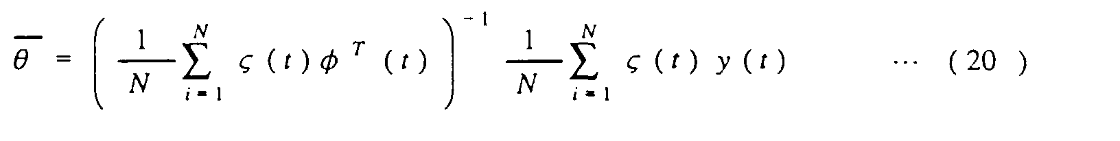
Note that Eq. (18) represents a regression vector, Eq. (19)
represents a correlation vector, and Eq. (20) is a model
parameter-projecting equation.
As shown in Fig. 14, Δ Pb - Mean(ΔPb) and -(Δ Δ Vw -
Mean(Δ Δ Vw)) or -(Δ Vw - Mean(Δ Vw)) are inputted as u(t) and y(t)
directly into the phase detector 53, however, a signal indicative of
y(t) may be passed through a low-pass filer before inputted into the
phase detector 53 for eliminating frequency noises occurring in the
suspension system of the vehicle. For example, 40Hz may be
removed from the signal indicative of y(t).
It is also advisable that gains of u(t) and y(t) in the phase
detector 53 be kept constant for eliminating adverse effects on
calculation of the phase delay which is caused by a difference
between the gains. This may be achieved by dividing u(t) and y(t)
by gains uk and uk (i.e., u(t) = u(t) / uk, y(t) = y(t) / yk) where uk =
k · u(t) + (1-k) · uk, yk = k · y(t) + (1-k) · yk, and k is a constant, e.g.,
0.2).
The antiskid brake control performed by the electronic
control circuit 40 will be described below.
Fig. 15 shows a program or sequence of logical steps in a
whole operation of the antiskid brake control. The program is
executed by time interrupt in the CPU at a regular interval of, for
example, 8msec. in synchronism with wheel speed-sampling
cycles.
After entering the program, the routine proceeds to step 100
wherein the vehicle speed VB (i.e., the speed of the vehicle body) is
projected. In this embodiment, the greatest of the speeds of the
wheels 1 to 4 is defined as the vehicle speed VB. Specifically, the
greatest of the wheel speeds Vw** of the wheels 1 to 4 derived in
step 300 in a previous program cycle is selected. Next, it is
determined whether or not the greatest wheel speed lies within an
allowable range of a given upper limit to a given lower limit. The
upper limit is defined by the sum of an increment of the vehicle
speed by a maximum actual acceleration of the vehicle and the
vehicle speed VB projected one program cycle earlier. The lower
limit is defined by the sum of a decrement of the vehicle speed by a
maximum actual deceleration of the vehicle and the vehicle speed
VB projected one program cycle earlier. If the greatest wheel
speed lies within the allowable range, it is determined as the
vehicle speed VB. Alternatively, if not, one of the upper and lower
limits closer to the greatest wheel speed is determined as the
vehicle speed VB.
The routine proceeds to step 200 wherein it is determined
whether the antiskid brake control should be initiated or not.
When the ON-signal is inputted from the brake switch 26, and any
of the four wheels 1 to 4 exceeds a given deceleration value, it is
determined that the antiskid brake control should be started. For
instance, when either of the front wheels 1 and 2 exceeds in
deceleration 0.8G or when either of the rear wheels 3 and 4
exceeds in deceleration 0.6G, the antiskid brake control is
determined to be started.
The peak of the road-tire adhesion µ depends upon road
surface conditions and the vehicle speed. Thus, in this discussion,
it is assumed that the vehicle is traveling on an asphalt road. The
antiskid brake control system selects a criterion for determining
the initiation of the antiskid brake control from a map as a
function of the vehicle speed.
If a YES answer is obtained in step 200, then the routine
proceeds to step 300 wherein the W/C pressure in each of the
wheel cylinders 11 to 14 of the wheels 1 to 4 is adjusted under the
antiskid brake control based on the speed of a corresponding one
of the wheels 1 to 4 determined as a function of the pulse signal
outputted from a corresponding one of the wheel speed sensors 5
to 8.
Fig. 16 shows an operation of the antiskid brake system
performed in step 300 of Fig. 15 for each wheel.
First, in step 101, the phase detector 53 determines a
difference in phase between the brake pressure change Δ Pb and
the wheel speed change Δ Vw or between the brake pressure
change Δ Pb and the change in wheel speed change Δ Δ Vw to find a
phase delay ** of the wheel speed change Δ Vw or the change in
wheel speed change Δ Δ Vw from the brake pressure change Δ Pb in
each of the wheels 1 to 4.
The routine proceeds to step 102 wherein a W-parameter
WP** is determined based on the wheel speed Vw** and the
vehicle speed VB which is employed in an operation, as will be
described later in detail, when the wheel speed Vw** decreases
below a value producing the maximum road-tire frictional force.
The W-parameter WP** is a feedback control factor which is used
in a conventional antiskid brake system to minimize an
undesirable acceleration produced when the road-tire adhesion µ
exceeds the peak thereof and given by the following equation.
WP**= K1(ΔVw**-ΔVB)+ K2(Vw**-VB)+ K3Σ(Vw**-VB)
where K1, K2, and K3 are weighting coefficients for a differential
term, a stationary term, and an integral term of Eq. (20), and ▵ Vw
** and ▵ VB are defined, as expressed blow, as changes for a
cycle of 0.1 sec.
Δ Vw** = Vw (n) - Vw (n - N)
Δ VB = VB (n) = VB (n- N )
where N = 0.1 / Ts, and Ts is a sampling cycle.
The routine proceeds to step 103 wherein it is determined
whether an absolute value of the W-parameter WP** is greater
than a threshold value Krec or not, thereby deciding whether a
recovery operation should be initiated or not. If the brake force
has exceeded the µ-peak brake force or a undesirable external
force has acted on the tire because of passage of the vehicle on a
step of the road, for example, a YES answer is obtained, and the
routine proceeds to step 104 to perform the recovery operation,
thereby bringing the slip ratio to a suitable one after a sudden drop
in wheel speed Vw**. Alternatively, if a NO answer is obtained,
then the routine proceeds to step 106 to perform a peak search
operation.
In step 104, the brake pressure PM** required to produce
the maximum road-tire frictional force is determined in the
following manner. The wheel acceleration Vw' and the W/C
pressure Pb (i.e., the brake pressure) has, as described in the
introductory part of this application, a relationship below.
I/rVw**' = Fmax - Kpad · Pb**
Eq. (24) may be replaced with a relation, as expressed by
equation (25) below, between a vehicle body deceleration
VB' and
the brake pressure
PM** matching the maximum road-tire
frictional force
Fmax.
I/rVB' = Fmax - Kpad · Pb**
From Eqs. (24) and (25), we obtain
PM** = I/r/Kpad(Vw**' - VB') + Pb**
However, since the determination of
Vw**
' and
VB' requires a
differential operation, which will result in an increase in noise,
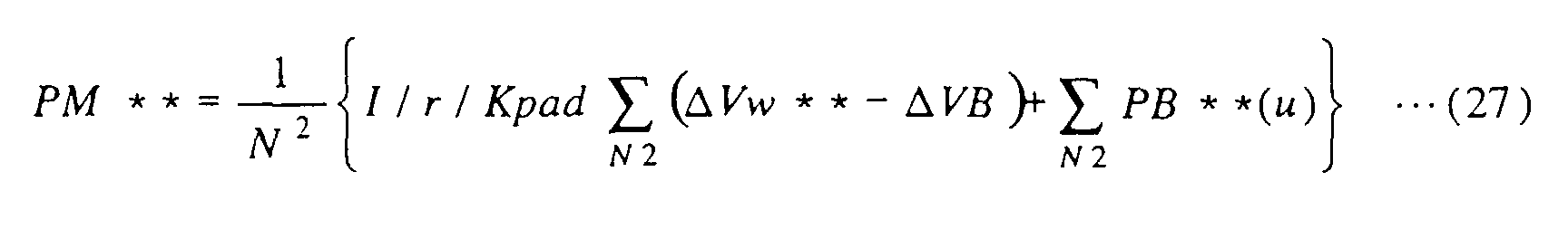
equation (27) below is, in practice, employed which is derived by
integrating and averaging Eq. (26) for a given period of time. Upon
finding
PM** and
VB', Fmax may be determined. In other words,
Eq. (26) serves as an observer of the maximum road-tire frictional
force.
where Δ
Vw** and Δ
VB are defined, as expressed blow, by
changes for a cycle of 0.1 sec.
Δ Vw** = Vw (n) - Vw (n - N 2)
Δ VB = VB (n) = VB (n - N 2)
In Eqs (24) to (29),
I is the moment of inertia of each wheel,
r is the
radius of tire,
Fmax is a maximum road-tire frictional force,
Kpad
is a brake pad constant,
Pb** is a current
W/C pressure,
N2 is
the number of samples for 0.1 sec. (= 0.1/
Ts).
The routine proceeds to step 105 wherein the brake
pressure PM** derived in step 104 is added to the product of the
W-parameter WP** derived in step 101 and a given gain Kwp to
determine a target brake pressure PN** to be developed in one of
the wheel cylinders 11 to 14.
If a NO answer is obtained in step 103, then the antiskid
brake control, as described above, enters the peak search mode to
select one of the pressure-increasing and pressure-holding
patterns as a function of the phase delay ** derived in step 101.
First, in step 106, it is determined whether the phase delay **
is greater than a given threshold value th or not. If a NO answer
is obtained meaning that the wheel speed lies within the range 1,
as shown in Fig. 2(b), then the routine proceeds to step 107 to
select a pressure-increasing pattern such as the one shown in Fig.
9. Alternatively, if a YES answer is obtained meaning that the
brake force is already in the vicinity of the µ -peak brake force, then
the routine proceeds to step 108 to select a pressure-holding
pattern such as the one shown in Fig. 10.
In the pressure-increasing pattern, as shown in Fig. 9, the
first increment of the brake pressure Pb has a smaller step width,
and a subsequent increment has a greater step width for
responding to a change in road surface condition quickly. If the
pressure-holding pattern is selected, a pressure-holding operation
initiating signal is changed depending upon whether a control
signal outputted to a corresponding one of the actuators 21 to 24
immediately before the pressure-holding mode is entered is a
pressure-increasing signal or a pressure-reducing signal.
Specifically, if the pressure-increasing signal is outputted
immediately before the pressure-holding mode is entered, the
control signal is provided which decreases the brake pressure or
W/C pressure first. Alternatively, if the pressure-reducing signal
is outputted immediately before the pressure-holding mode is
entered, the control signal is provided which increases the W/C
pressure first.
Specifically, when the pressure-increasing mode is entered,
the recovery circuit 60 determines a hydraulic
increment/decrement Δ PN which increments the W/C pressure by
0.5Mpa 0.05sec. after the initiation of the pressure-increasing
mode and further increments the W/C pressure by 0.5Mpa 0.1sec.
after the initiation of the pressure-increasing mode. Alternatively,
when the pressure-holding mode is entered, the recovery circuit 60
produces the hydraulic increment/decrement Δ PN which
increments the W/C pressure by 0.05Mpa 0.05sec. after the
initiation of the pressure-increasing mode and decrements the
W/C pressure by 0.05Mpa 0.1sec. after the initiation of the
pressure-increasing mode.
If the value of the hydraulic increment/decrement Δ PN is
too small, it will cause the pressure-increasing signal (referred to
below as TUP**) or the pressure-reducing signal (referred to
below as TDW**) outputted to the solenoid of a corresponding
one of the actuators 21 to 24 to be too small to energize the
solenoid. Even if it is possible to energize the solenoid, a change
in W/C pressure is insufficient for changing the wheel speed to
enable the phase delay to be determined. Therefore, the recovery
circuit 60 determines the hydraulic increment/decrement Δ PN so
that the pulse width or output duration of each of the
pressure-increasing and pressure-reducing signals TUP**and
TDW** may be equivalent to 3msec. or more. Specifically, if a
change in W/C pressure calculated in a case where the pulse width
of the pressure-increasing signal TUP** is set to 3msec. is
defined as ▵ PN3, it may be expressed as
▵ PN3 = KUP·TUP**
In a case where it is possible to measure the pressure Pmc
in the master cylinder 16 directly through a pressure sensor, ▵
PN3 may be expressed as
Δ PN3 = (Pmc - Pb**) EXP(-KUP · TUP**)
Similarly, Δ PN3 calculated in a case where the pulse width
of the pressure-reducing signal TDW** is set to 3msec. may be
expressed as
Δ PN3 = Pb** (1 - EXP(-KDW · TDW**))
If the value of Δ PN3 is smaller than a desired pressure
change of 0.5MPa, then the hydraulic increment/decrement Δ PN is
set equal to Δ PN3. Alternatively, if the value of Δ PN3 is greater
then 0.5MPa, it means that it is possible to provide a pulse having
a width (i.e., the output duration of the pressure-reducing signal
TDW**) sufficient for energizing the solenoids of the actuators 21
to 24, and thus, the hydraulic increment/decrement ▵ PN is set to
0.5MPa.
After the hydraulic increment/decrement ▵ PN is
determined in the above manner, the routine proceeds to step 109
wherein the hydraulic increment/decrement ▵ PN** is added to
the W/C pressure Pb** to determine the target brake pressure
PN** (i.e., a target W/C pressure).
After step 105 or 109, the routine proceeds to step 110
wherein the hydraulic servomechanism 70 determines the
pressure-increasing signal TUP** or the pressure-reducing signal
TDW** which brings the W/C pressure into agreement with the
target brake pressure PN**.
Fig. 17 shows an operation performed in step 110 of Fig. 16
by the hydraulic servomechanism 70.
First, in step 401, it is determined whether the target brake
pressure PN** is greater than the W/C pressure Pb**
developed one program cycle earlier, that is, an estimated current
level of the W/C pressure Pb** or not. If a YES answer is
obtained (PN**>Pb**), then the routine proceeds to step 402 to
initiate the pressure-increasing mode. Alternatively, if a NO
answer is obtained, then the routine proceeds to step 412 to
initiate the pressure-reducing mode.
In step 402, it is determined whether the target brake
pressure PN** is greater than a maximum pressure KPMAX (e.g.,
30MPa) or not. If a NO answer is obtained (KPMAX>PN**), then
the routine proceeds to step 405 wherein the maximum pressure
KPMAX is defined as pressure PMAX**. The routine proceeds to
step 408 wherein an output duration of the pressure-increasing
signal TUP** is set to be equal to the sampling cycle Ts for
increasing the W/C pressure at a full rate, and the W/C pressure
Pb** is set to the pressure PMAX**.
Alternatively, if a YES answer is obtained in step 402, then
the routine proceeds to step 403 wherein the sum of KUP that is an
increment of the W/C pressure when the pressure-increasing
signal TUP** is outputted for the sampling cycle Ts and a
current level of the W/C pressure Pb** is defined as the pressure
PMAX**.
The routine proceeds to step 404 wherein it is determined
whether the target brake pressure PN** is smaller then the
pressure PMAX** or not. If a NO answer is obtained (PN**>
PMAX**), then the routine proceeds to step 408. Alternatively, if
a YES answer is obtained, then the routine proceeds to step 406
wherein the output duration of the pressure-increasing signal TUP
** is determined according to equation (33) below.
TUP** = (PN** - Pb**) / KUP
The routine proceeds to step 407 wherein it is determined
whether the output duration of the pressure-increasing signal TUP
** derived in step 406 is greater than KTUPMIN or not that is a
minimum energization time of the solenoid of each of the actuators
21 to 24. If a NO answer is obtained meaning that there is the
possibility of failure in operation of the solenoid resulting in an
error in the antiskid brake control, the routine terminates without
outputting the pressure-increasing signal TUP** and updating
the W/C pressure Pb**. Alternatively, if a YES answer is
obtained, then the routine proceeds to step 409 wherein the W/C
pressure Pb** is updated and set to the target brake pressure PN
**.
After step 408 or 409, the routine proceeds to step 410
wherein the output duration of the pressure-increasing signal TUP
* * derived in step 408 or 409 is set in a solenoid energization
timer of the hydraulic servomechanism 70. The hydraulic
servomechanism 70 outputs the pressure-increasing signal TUP**
to one of the actuators 21 to 24, thereby increasing the W/C
pressure in a corresponding one of the wheel cylinders 11 to 14.
If a NO answer is obtained in step 401, the antiskid brake
control enters the pressure-reducing mode. First, in step 412, it
is determined whether the target brake pressure PN** is greater
than a minimum pressure KPMIX (e.g., 0.2MPa) or not. If a NO
answer is obtained (KPMIX>PN**), then the routine proceeds to
step 415 wherein the minimum pressure KPMIX is defined as
pressure PMIX**. The routine proceeds to step 418 wherein an
output duration of the pressure-increasing signal TDW** is set
to be equal to the sampling cycle Ts for decreasing the W/C
pressure at a full rate, and the W/C pressure Pb** is set to the
pressure PMIX**.
Alternatively, if a YES answer is obtained in step 412, then
the routine proceeds to step 413 wherein the value of KDW that is
a decrement of the W/C pressure when the pressure-reducing
signal TDW** is outputted for the sampling cycle Ts is
substituted into an equation below to obtain the pressure the
pressure PMIX**.
PMIN** = Pb** ·EXP(-KDW·Ts)
The routine proceeds to step 414 wherein it is determined
whether the target brake pressure PN** is smaller then the
pressure PMIX** or not. If a NO answer is obtained (PN**>
PMIX**), then the routine proceeds to step 418. Alternatively, if
a YES answer is obtained, then the routine proceeds to step 416
wherein the output duration of the pressure-increasing signal TDW
** is determined according to an equation below.
TDW** = -1 / KDW · log(PN** / Pb**)
The routine proceeds to step 417 wherein it is determined
whether the output duration of the pressure-reducing signal TDW
** derived in step 416 is greater than KTDWMIN or not that is a
minimum energization time of the solenoid of each of the actuators
21 to 24. If a NO answer is obtained meaning that there is the
possibility of failure in operation of the solenoid resulting in an
error in the antiskid brake control, the routine terminates without
outputting the pressure-reducing signal TDW** and updating
the W/C pressure Pb**. Alternatively, if a YES answer is
obtained, then the routine proceeds to step 419 wherein the W/C
pressure Pb** is updated and set to the target brake pressure PN
**.
After step 418 or 419, the routine proceeds to step 420
wherein the output duration of the pressure-increasing signal TDW
** derived in step 418 or 419 is set in the solenoid energization
timer of the hydraulic servomechanism 70. The hydraulic
servomechanism 70 outputs the pressure-reducing signal TDW**
to one of the actuators 21 to 24, thereby decreasing the W/C
pressure in a corresponding one of the wheel cylinders 11 to 14.
Figs. 18(a), 18(b), and 18(c) are time charts for explaining
the antiskid brake operation in a case where the vehicle equipped
with the antiskid brake system of this embodiment is braked
during traveling at 70Km/h.
Fig. 18(a) shows the wheel speed Vw, the estimated W/C
pressure Pb, the transfer gain, and the phase delay . Fig. 18(b)
shows the brake pressure change ▵ Pb and the change in wheel
speed change ▵ ▵ Vw. Fig. 18(c) shows the inverses in sign of the
brake pressure change ▵ Pb and the change in wheel speed change
▵ ▵ Vw from which offsets are removed, that is, {-( ▵ ▵ Vw -
Mean(▵ ▵ Vw))} and {▵ Pb - Mean(▵ Pb)}.
The phase delay is determined from values shown in Fig.
18(c). The change in wheel speed change ▵ ▵ Vw changes with a
change in W/C pressure Pb and becomes delayed in phase. Based
on this change in phase, the phase delay is determined. When
the phase delay decreases below the threshold value th, the
pressure-holding mode is, as described above, entered, so that
estimated W/C pressure Pb is kept constant. This minimizes a
drop in wheel speed which is caused by the brake force exceeds the
µ-peak brake force, thereby providing a suitable brake force under
the antiskid brake control.
The antiskid brake system of this embodiment, as described
above, uses the pressure-increasing pattern such as the one shown
in Fig. 19(a), however, may employ another pattern as shown in Fig.
19(b) or 19(c). In the pressure-increasing pattern of Fig. 19(b), a
period of time during which four successive pulse signals
outputted to one of the actuators 21 to 24 is defined as one
pressure-increasing cycle. During one pressure-increasing cycle,
the W/C pressure Pb is, in sequence, increased, increased, held,
and increased. In the pressure-increasing pattern of Fig. 19(c),
one pressure-increasing cycle is divided into three regular cycles in
which the W/C pressure is stepped up.
In a case where it is possible to measure the brake pressure
PM in the master cylinder 16 using a pressure sensor, the
equations used in step 403 and 406 of Fig. 17 may be replaced
with ones below.
PUPMAX** = Pb** + (PM -Pb**) EXP(-KUP·Ts)
TUP** = -1/KUP · log((PM - PN**) / (PM - Pb**))
The above embodiment uses the W/C pressure Pb as a
parameter reflecting on the brake torque, however, may employ
another parameter reflecting on the brake torque or the brake
torque itself.
It is advisable that the number of pulse signals or frequency
thereof to be applied to the actuators 21 to 24 to increase the W/C
pressure Pb in one control cycle, as shown in Figs. 9, 10, 19(b),
and 19(c), be limited to a specific value. Usually, the resonant
vibration produced at a suspension system is mainly transmitted
to each wheel. Such resonant vibration is caused by the
resonance of the vehicle body or engine with the suspension
system and has different frequencies between types of vehicles,
usually 15Hz to 40Hz. The resonant frequency of 15Hz is caused
by the resonance of the vehicle in a vertical direction thereof. The
resonant frequency of 40Hz is caused by the resonance of the
vehicle in a longitudinal direction thereof. It is, thus, advisable
that the frequency of the pressure-increasing pulse signals
provided to energize the actuators 21 to 24 be selected from a
range excluding the resonance frequencies of 15Hz to 40Hz,
thereby eliminating adverse effects of the resonant frequency in the
suspension system on signals used to determine the brake
pressure change Δ Pb and the W/C pressure Pb and also
minimizing the resonance of the W/C pressure or valves of the
actuators 21 to 24 with the suspension system. Usually, it is
impossible to apply forty pressure-increasing pulses to the
actuators 21 to 24 because of the limit of response rate thereof. It
is, thus, preferable that the frequency of the pressure-increasing
pulses be less than 10Hz.
The above described adverse effects of the resonant
frequency in the suspension system may alternatively be
eliminated by removing the resonant frequency from a sensor
signal indicative of the wheel speed Vw using a band-pass filter or
a low-pass filter. For instance, 15Hz±5Hz and 40Hz±5Hz are
preferably removed from the sensor signal. Alternatively, only a
component of the sensor signal within a range less than 15Hz or
more than 40Hz may be employed to determine the wheel speed
Vw. The removal of the resonance frequency from the sensor
signal may also be performed when reducing the W/C pressure.
Each of the actuators 21 to 24, as illustrated in Fig. 12, is
implemented by a three-position control valve, however, a
two-position control valve designed to selectively increase and hold
the W/C pressure may be employed. In this case, a
pressure-reducing two-position control valve is installed between
each of the actuators 21 to 24 and a corresponding one of the
reservoirs 28a and 28b. Instead of the pressure-increasing
two-position control valves, linear control valves may be employed
which are each designed to move a valve body thereof linearly as a
function of the amount of current supplied to a solenoid. In this
case, it is advisable that the harmonic or great hydraulic pressure
change occurring when the pressure-increasing pulse, as shown in
Figs. 9, 10, 19(b), and 19(c), rises be minimized to eliminate
unwanted noises disturbing the calculation of the brake pressure
change Δ Pb. This may be achieved by smoothing an upper corner
of a rising edge of each pressure-increasing pulse.
Fig. 20 shows a modification of the electronic control circuit
40 in Fig. 13 which is designed to eliminate the adverse effects of
the resonant vibration occurring in the suspension system caused
by traveling of the vehicle on steps or irregularities in the road.
A resonance-detecting circuit 96 detects resonant
frequencies of 15Hz and/or 40Hz contained in the signal indicative
of the wheel speed Vw and compares a gain of the vibration of the
suspension system with a threshold value. If either of the gains is
greater than the threshold value meaning that the vehicle is
traveling on an uneven road surface, a switch 93 switches a
connection of the pressure-increasing and -holding pattern
selecting circuit 53 to the switch 71 to a connection of a
pressure-increasing and -holding pattern selecting circuit 90 to the
switch 71. The pressure-increasing and -holding pattern selecting
circuit 90 produces a pressure-increasing pattern or a
pressure-holding pattern which increases the rate at which the
W/C pressure rises, thereby eliminating a lag in increasing the
W/C pressure.
While the present invention has been disclosed in terms of
the preferred embodiments in order to facilitate better
understanding thereof, it should be appreciated that the invention
can be embodied in various ways without departing from the
principle of the invention. Therefore, the invention should be
understood to include all possible embodiments and modifications
to the shown embodiments witch can be embodied without
departing from the principle of the invention as set forth in the
appended claims.