EP1110804A1 - Apparatus for adjusting the inclination of a backrest of a vehicle seat - Google Patents
Apparatus for adjusting the inclination of a backrest of a vehicle seat Download PDFInfo
- Publication number
- EP1110804A1 EP1110804A1 EP00111516A EP00111516A EP1110804A1 EP 1110804 A1 EP1110804 A1 EP 1110804A1 EP 00111516 A EP00111516 A EP 00111516A EP 00111516 A EP00111516 A EP 00111516A EP 1110804 A1 EP1110804 A1 EP 1110804A1
- Authority
- EP
- European Patent Office
- Prior art keywords
- electric motor
- gear
- adjusting
- rotor
- hand wheel
- Prior art date
- Legal status (The legal status is an assumption and is not a legal conclusion. Google has not performed a legal analysis and makes no representation as to the accuracy of the status listed.)
- Granted
Links
- 230000009467 reduction Effects 0.000 claims description 13
- 230000005540 biological transmission Effects 0.000 claims description 7
- 230000008878 coupling Effects 0.000 description 7
- 238000010168 coupling process Methods 0.000 description 7
- 238000005859 coupling reaction Methods 0.000 description 7
- 208000027418 Wounds and injury Diseases 0.000 description 2
- 230000006378 damage Effects 0.000 description 2
- 208000014674 injury Diseases 0.000 description 2
- 230000004913 activation Effects 0.000 description 1
- 239000000470 constituent Substances 0.000 description 1
- 238000010276 construction Methods 0.000 description 1
- 230000006870 function Effects 0.000 description 1
- 239000000463 material Substances 0.000 description 1
- 230000006386 memory function Effects 0.000 description 1
- 230000001603 reducing effect Effects 0.000 description 1
- 230000002441 reversible effect Effects 0.000 description 1
Images


Classifications
-
- B—PERFORMING OPERATIONS; TRANSPORTING
- B60—VEHICLES IN GENERAL
- B60N—SEATS SPECIALLY ADAPTED FOR VEHICLES; VEHICLE PASSENGER ACCOMMODATION NOT OTHERWISE PROVIDED FOR
- B60N2/00—Seats specially adapted for vehicles; Arrangement or mounting of seats in vehicles
- B60N2/02—Seats specially adapted for vehicles; Arrangement or mounting of seats in vehicles the seat or part thereof being movable, e.g. adjustable
- B60N2/22—Seats specially adapted for vehicles; Arrangement or mounting of seats in vehicles the seat or part thereof being movable, e.g. adjustable the back-rest being adjustable
- B60N2/225—Seats specially adapted for vehicles; Arrangement or mounting of seats in vehicles the seat or part thereof being movable, e.g. adjustable the back-rest being adjustable by cycloidal or planetary mechanisms
- B60N2/2251—Seats specially adapted for vehicles; Arrangement or mounting of seats in vehicles the seat or part thereof being movable, e.g. adjustable the back-rest being adjustable by cycloidal or planetary mechanisms with gears having orbital motion, e.g. sun and planet gears
-
- B—PERFORMING OPERATIONS; TRANSPORTING
- B60—VEHICLES IN GENERAL
- B60N—SEATS SPECIALLY ADAPTED FOR VEHICLES; VEHICLE PASSENGER ACCOMMODATION NOT OTHERWISE PROVIDED FOR
- B60N2/00—Seats specially adapted for vehicles; Arrangement or mounting of seats in vehicles
- B60N2/02—Seats specially adapted for vehicles; Arrangement or mounting of seats in vehicles the seat or part thereof being movable, e.g. adjustable
- B60N2/0224—Non-manual adjustments, e.g. with electrical operation
- B60N2/02246—Electric motors therefor
-
- H—ELECTRICITY
- H02—GENERATION; CONVERSION OR DISTRIBUTION OF ELECTRIC POWER
- H02K—DYNAMO-ELECTRIC MACHINES
- H02K7/00—Arrangements for handling mechanical energy structurally associated with dynamo-electric machines, e.g. structural association with mechanical driving motors or auxiliary dynamo-electric machines
- H02K7/10—Structural association with clutches, brakes, gears, pulleys or mechanical starters
- H02K7/116—Structural association with clutches, brakes, gears, pulleys or mechanical starters with gears
Landscapes
- Engineering & Computer Science (AREA)
- Aviation & Aerospace Engineering (AREA)
- Transportation (AREA)
- Mechanical Engineering (AREA)
- Power Engineering (AREA)
- Chairs For Special Purposes, Such As Reclining Chairs (AREA)
- Seats For Vehicles (AREA)
Abstract
Description
- The present invention relates to an apparatus for adjusting the inclination of a backrest of a vehicle seat.
- It is known to adjust the inclination of the backrest of the vehicle seat using an electric motor and/or hand wheel which act via an adjusting gear on an adjustable rigid back rest frame.
- The present invention provides a compact apparatus for adjusting the inclination of a backrest of a vehicle seat comprising both a hand wheel and an electric motor as adjusting drives. With the invention, the hand wheel is arranged coaxial with the rotor of the electric motor and the hand wheel forms a hood-shaped housing that receives the motor components in the interior of the hood-shaped housing. The hand wheel and the electric motor also preferably possess a common output shaft connected to the adjusting gear. Advantageously, the rotor of the electric motor and the hand wheel can be arranged coaxially to the output shaft for this purpose, and the hand wheel can be non-rotatably connected to the output shaft from a released position by hand, for example by exertion of pressure.
- The reduction gear is preferably integrated into the electric motor. It can be designed as a planetary gear as known, for example, from DE 43 02 042 A1.
- With the adjusting device according to the invention, the inclination of the backrest can be adjusted both manually and electrically, and the components required for these adjusting drives are accommodated compactly. The backrest can be adjusted for comfort. The backrest can also be pre-adjusted for safety if there is a risk of a crash that is possibly detected by precrash sensors. Sensor signals of this type can be obtained, for example, from the brake pressure, from the electrical stability control of the vehicle, from information concerning longitudinal, transverse and vertical deceleration or external distance sensors and the like. The pivoting of the back rest is reversible owing to the electric motor drive, i.e., if there is no crash, the back rest can be brought back to its original inclination.
- A basic safety adjustment of the back rest can be achieved automatically by appropriate control of the electric motor drive by means of electric signals which are proportional to the weight of the vehicle occupant, the longitudinally adjusted position of the seat and/or the extracted length of belt webbing. Manual actuation by the hand wheel is possible in the event of a power failure.
- The invention will be described in more detail by means of an embodiment with reference to the figures, in which:
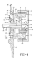
- Fig. 1 is a sectional view through an embodiment of the invention;
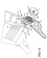
- Fig. 2 shows a perspective arrangement of the embodiment on a vehicle seat;
- Fig. 3 is a side view of a vehicle seat on which an embodiment of the invention is provided; and
- Fig. 4 is a sectional view of a further embodiment of the invention.
-
- The illustrated embodiments have an
electric motor 1 of which the constituents are arranged in the interior of ahand wheel 3. Theelectric motor 1 comprises astator 7 which is anchored via anadapter 19 on agear part 10 rigidly connected to theseat frame 8. In the interior of thestator 7 there is areduction gear 9 that is designed as a planetary gear in the embodiments illustrated. The planetary gear comprisesplanet wheels 16 which mesh with aring gear 21 provided on the interior of thestator 7. Theplanet wheels 16 are mounted rotatably on aplanet wheel carrier 13. The stator of the electric motor is advantageously fastened on the seat frame and, in particular, on the gear part of the adjusting gear that is anchored on the seat frame. In a known manner, the adjusting gear can comprise a cam the shaft of which is surrounded by a wobble plate which is rigidly connected to the adjustable back rest frame and engages with external teeth in internal teeth on the gear part rigidly connected to the seat frame. The camshaft is connected non-rotatably to the output shaft that is driven either by the electric motor and/or by the hand wheel. With the design of the reduction gear integrated in the electric motor as a planetary gear, the planet wheel carrier can be connected non-rotatably to the output shaft. The torque delivered by the electric motor is therefore transmitted from the planet wheel carrier to the output shaft. The output shaft can advantageously be lengthened to a transmission shaft that extends substantially over the entire width of the seat and is connected to the backrest frame on both sides of the vehicle seat. The rotatable mounting of the electric motor rotor can be provided on the transmission shaft or on an extension thereof. The rotor can also be supported rotatably via the planetary gear on the stator on which the ring gear of the planetary gear is formed. - The electric motor also comprises a
rotor 2 that is designed as an external rotor. Therotor poles 22 are permanent magnets. The rotor of the electric motor is preferably designed as an external rotor that acts via a reduction gear on the adjusting gear which also acts as a reduction gear and is rigidly connected to the adjustable back rest frame by its adjustable part. Gear reductions of 1:150 can therefore be achieved. Output torques of about 1200 Nm can be caused to act on the output shaft. The hand wheel can also be formed from one piece with the rotor of the electric motor - The
rotor 2 is hood-shaped in design and possesses on a bearing collar 17 asun wheel 11 with which the planet wheels, for example theplanet wheels 16, mesh. Thebearing collar 17 can be rotatably mounted on abearing journal 18, as shown in Fig. 4. Thebearing collar 17 and therefore therotor 2 can also be rotatably mounted via theplanetary gear 9 on thestator 7 andadapter 19, as shown in Fig. 1. The electric motor with the integrated planetary gear has a construction of the type known, for example, from DE 43 02 042 A1. The torque produced by the electric motor is transmitted via theplanet wheel carrier 13 to anoutput shaft 12. For this purpose, theoutput shaft 12 can comprise atoothing notch 26 by means of which a non-rotatable connection between theplanet wheel carrier 13 and theoutput shaft 12 is produced. Acoupling part 30 rotatably mounted on theseat frame 8 also engages non-rotatably with the toothingnotch 26 of theoutput shaft 12. A compensatingspring 31 which acts on awobble plate 20 of the adjustinggear 4 is connected non-rotatably to thecoupling part 30. - A direct rotary connection between the
planet wheel carrier 13 and thecoupling part 30 can also be provided instead of the non-rotatable connection between theplanet wheel carrier 13 and thecoupling part 30 via theoutput shaft 12 provided with thetoothing notch 26. As shown in Figs. 1 and 4, the components of theelectric motor 1 and of the reduction gear (planetary gear) 9 integrated therein are located in the interior of thehand wheel 3 which is designed in the shape of a hood and which surrounds this unit as a housing. - In the embodiment shown in Fig. 1, the rotor of the
electric motor 1 and thehand wheel 3 consist of one piece. In the embodiment shown in Fig. 4, thehand wheel 3 surrounds therotor 2 in the form of a housing. For this purpose, thehand wheel 3 is also designed in the shape of a hood. Thehand wheel 3 is normally held out of rotational engagement with theoutput shaft 12 by means of a restoringspring 27. As a result, the rotational movement of therotor 2 takes place when thehand wheel 3 is stationary. For coupling thehand wheel 3, thehand wheel 3 can be displaced axially against the force of the restoringspring 27 by anengagement part 29. Theengagement part 29 thus interlocks positively with anengagement part 28 on theoutput shaft 12 or on thebearing journal 18 formed integrally with theoutput shaft 12. Theengagement parts output shaft 12 by means of the hand wheel. - As already mentioned, the rotational movement of the
output shaft 12 is transmitted via thecoupling part 30 to an adjustinggear 4. The adjustinggear 4 consists of a cam with acamshaft 14. Thecamshaft 14 is surrounded by awobble plate 20 that is rigidly connected to abackrest frame 5 consisting of rigid material. Thewobble plate 20 hasexternal teeth 24 which engage ininternal teeth 25 of thegear part 10 rigidly connected to theseat frame 8 within an angular range of engagement. Owing to the gear reduction of, for example, 1:150, which can be achieved when theplanetary gear 9 interacts with the adjustinggear 4 which has a reducing action, output torques of about 1200 Nm can be transmitted during adjustment of the back rest. - The
output shaft 12 can be lengthened in one piece over the width of the seat and can form atransmission shaft 15. Thetransmission shaft 15 can be connected to arespective adjusting gear 4 on both sides of the seat. Anelectric motor 1 with associatedhand wheel 3 can optionally be provided on both sides. - The electric motor is preferably a brushless d.c. motor. Smoothly controlled adjustment rates can thus be achieved to allow, for example, a slow start, a fast intermediate adjustment and a precise fine adjustment of the inclination of the back rest. This can be achieved by appropriate actuation of the switch.
- The motor can detect, for example, its respective zero position by initialization, for example during activation of the central locking. An integrated memory function for a respective starting position of the back rest can thus be achieved, into which the back rest can automatically be returned after an adjustment.
- Owing to the high output torque which can be achieved, it is possible to bring the
back rest 6 in short-time duty into a safety position in which risks of injury, in particular in the event of a rear impact, are clearly reduced. This pivoting of the backrest can be carried out reversibly and can optionally take place as a function of sensor signals of a precrash sensor. - Owing to the pivoting of the back rest which takes place within a short period of time, for example from a comfort position which is shown in solid lines in Fig. 3 into the safety position which reduces the risk of injury and is shown in broken lines in Fig. 3, a forwardly and upwardly directed adjustment of a
head rest 23 can take place at the same time. This adjustment of the headrest can be carried out actively by the rotation of thetransmission shaft 15 during the pivoting of the backrest via a suitable gear. -
- 1
- electric motor
- 2
- rotor
- 3
- hand wheel
- 4
- adjusting gear
- 5
- back rest frame
- 6
- back rest
- 7
- stator
- 8
- seat frame
- 9
- reduction gear
- 10
- gear part
- 11
- sun wheel
- 12
- output shaft
- 13
- planet wheel carrier
- 14
- cam shaft
- 15
- transmission shaft
- 16
- planet wheel
- 17
- bearing collar
- 18
- bearing journal
- 19
- adapter
- 20
- wobble plate
- 21
- ring gear
- 22
- rotor poles
- 23
- head rest
- 24
- external teeth
- 25
- internal teeth
- 26
- toothing notch
- 27
- restoring spring
- 28
- engagement part
- 29
- engagement part
- 30
- coupling part
- 31
- compensating spring
Claims (10)
- An apparatus for adjusting the inclination of a back rest (6) of a vehicle seat with an electric motor (1) and a hand wheel (3) as adjusting drives which act on the adjustable back rest frame (5) via an adjusting gear (4), characterised in that the hand wheel (3) is arranged coaxially to the rotor (2) of the electric motor and accommodates the motor components as a hood-shaped housing in its interior.
- The apparatus according to claim 1, characterised in that the hand wheel (3) surrounds the rotor (2) of the electric motor (1) in the manner of a hood and can be brought into rotational engagement with the adjusting gear (4) by hand.
- The apparatus according to either of claims 1 or 2, characterised in that the hand wheel (3) and the electric motor (1) have a common output shaft (12) connected to the adjusting gear (4).
- The apparatus according to one of claims 1 to 3, characterised in that the rotor (2) is designed as an external rotor of the electric motor (1) and the stator (7) of the electric motor (1) is supported on the seat frame (8).
- The apparatus according to one of claims 1 to 4, characterised in that the rotor (2) is connected via a reduction gear (9) to the adjusting gear (4) which also comprises a reduction.
- The apparatus according to one of claims 1 to 5, characterised in that the reduction gear (9) is integrated in the electric motor (1) and is designed as a planetary gear.
- The apparatus according to one of claims 1 to 6, characterised in that the adjusting gear (4) comprises a cam which is driven by the adjusting drive, the cam shaft (14) of which is surrounded by a wobble plate (20) which is rigidly connected to the adjustable back rest frame (5) and engages with external teeth in internal teeth on the gear part (10) rigidly connected to the seat frame (8).
- The apparatus according to one of claims 1 to 7, characterised in that the cam shaft (14) is connected non-rotatably to the output shaft (12).
- The apparatus according to one of claims 1 to 8, characterised in that the planet wheel carrier (13) of the reduction gear (9) designed as a planetary gear is connected non-rotatably to the output shaft (12).
- The apparatus according to one of claims 1 to 9, characterised in that the output shaft (12) is extended to a transmission shaft (15) which extends substantially over the entire width of the seat and is connected to the back rest frame (5) on both sides of the vehicle seat via the two-sided adjusting gear (4).
Applications Claiming Priority (2)
| Application Number | Priority Date | Filing Date | Title |
|---|---|---|---|
| DE19962225A DE19962225A1 (en) | 1999-12-22 | 1999-12-22 | Device for adjusting the inclination of a backrest of a vehicle seat |
| DE19962225 | 1999-12-22 |
Publications (2)
| Publication Number | Publication Date |
|---|---|
| EP1110804A1 true EP1110804A1 (en) | 2001-06-27 |
| EP1110804B1 EP1110804B1 (en) | 2005-08-10 |
Family
ID=7933946
Family Applications (1)
| Application Number | Title | Priority Date | Filing Date |
|---|---|---|---|
| EP00111516A Expired - Lifetime EP1110804B1 (en) | 1999-12-22 | 2000-05-29 | Apparatus for adjusting the inclination of a backrest of a vehicle seat |
Country Status (4)
| Country | Link |
|---|---|
| US (1) | US6331034B1 (en) |
| EP (1) | EP1110804B1 (en) |
| DE (2) | DE19962225A1 (en) |
| ES (1) | ES2246203T3 (en) |
Cited By (5)
| Publication number | Priority date | Publication date | Assignee | Title |
|---|---|---|---|---|
| WO2005100080A1 (en) * | 2004-04-15 | 2005-10-27 | Keiper Gmbh & Co. Kg | Drive unit of a regulating element for a vehicle seat |
| WO2005100078A3 (en) * | 2004-04-15 | 2006-01-19 | Keiper Gmbh & Co Kg | Regulating element for a vehicle seat |
| US7294081B2 (en) | 2004-04-15 | 2007-11-13 | Keiper Gmbh & Co. Kg | Drive unit for a vehicle seat |
| US7329200B2 (en) | 2004-04-15 | 2008-02-12 | Keiper Gmbh & Co. Kg | Drive unit of an adjuster of a vehicle seat |
| US7544143B2 (en) | 2004-04-15 | 2009-06-09 | Keiper Gmbh & Co. Kg | Drive unit of an adjuster in a vehicle |
Families Citing this family (17)
| Publication number | Priority date | Publication date | Assignee | Title |
|---|---|---|---|---|
| DE19952963A1 (en) * | 1999-11-03 | 2001-05-23 | Bosch Gmbh Robert | Device for adjusting a seat back with load compensation |
| BR0117049A (en) * | 2001-06-12 | 2004-07-27 | Isringhausen S P A | Device for adjusting the position of at least one movable part of a vehicle seat, and, vehicle seat |
| DE10327090B4 (en) * | 2003-06-13 | 2007-03-29 | C. Rob. Hammerstein Gmbh & Co. Kg | Articulated fitting for an adjustment of a motor vehicle seat |
| JP4170892B2 (en) * | 2003-12-16 | 2008-10-22 | 本田技研工業株式会社 | Vehicle occupant protection device |
| CN1922416B (en) * | 2004-02-06 | 2010-05-05 | L&P产权管理公司 | Drive mechanism |
| US7644987B2 (en) | 2004-09-27 | 2010-01-12 | Lear Corporation | Vehicle seat having active head restraint system |
| DE102007017617B4 (en) * | 2006-11-02 | 2016-06-09 | Johnson Controls Gmbh | Adjustment of a motor vehicle seat |
| WO2009008884A1 (en) * | 2007-07-09 | 2009-01-15 | Johnson Controls Gmbh | Recliner mechanism for vehicle seat |
| DE102008045350B4 (en) * | 2008-08-28 | 2010-12-09 | Keiper Gmbh & Co. Kg | Actuating device for a vehicle seat, system with an actuator and vehicle seat |
| DE102011016646A1 (en) * | 2011-04-09 | 2012-10-11 | GM Global Technology Operations LLC (n. d. Gesetzen des Staates Delaware) | Backrest adjustment device for a vehicle seat or a vehicle seat |
| WO2012152727A2 (en) * | 2011-05-06 | 2012-11-15 | Johnson Controls Gmbh | Planetary gear arrangement for a seat adjustment mechanism and method for operating such a planetary gear arrangement |
| DE102011113747A1 (en) * | 2011-09-14 | 2013-03-14 | Keiper Gmbh & Co. Kg | Fitting system for a vehicle seat |
| US11353084B2 (en) * | 2013-03-15 | 2022-06-07 | Clearmotion Acquisition I Llc | Rotary actuator driven vibration isolation |
| JP6232983B2 (en) * | 2013-12-03 | 2017-11-22 | アイシン精機株式会社 | Deceleration device and seat drive device |
| DE202013011803U1 (en) * | 2013-12-04 | 2015-03-11 | Brose Fahrzeugteile Gmbh & Co. Kommanditgesellschaft, Coburg | Vehicle seat with a locking device for a rotatable backrest |
| DE102017102535B4 (en) * | 2017-02-09 | 2020-07-09 | Faurecia Autositze Gmbh | Adjustment arrangement for adjusting a vehicle seat component, vehicle seat and method for producing an adjustment arrangement |
| KR102348183B1 (en) * | 2020-04-09 | 2022-01-06 | 황종성 | A chair |
Citations (7)
| Publication number | Priority date | Publication date | Assignee | Title |
|---|---|---|---|---|
| US3401979A (en) * | 1966-07-19 | 1968-09-17 | Putsch Friedrich W | Articulated mount for seats, particularly motor vehicle seats |
| US3972563A (en) * | 1975-09-04 | 1976-08-03 | Gustaf Erik Gustafsson | Seatback tilt adjustment mechanism |
| US4143912A (en) * | 1976-03-27 | 1979-03-13 | Manfred Schlappig | Adjustable hinge joint |
| DE4302042A1 (en) * | 1993-01-26 | 1994-07-28 | Hs Tech & Design | Compact, flat construction electromotor |
| FR2735083A3 (en) * | 1996-02-13 | 1996-12-13 | Zagyansky Yuly | Life-saving device for occupants of road vehicle in collision |
| DE19630325A1 (en) * | 1995-07-28 | 1997-03-06 | Imasen Denki Seisakusho Inuyam | Motor-operated seat adjustment device |
| DE19724555C1 (en) * | 1997-06-11 | 1998-11-05 | Faure Bertrand Sitztech Gmbh | Motor vehicle seat with inclinable back-rest adjustable by electric motor |
Family Cites Families (4)
| Publication number | Priority date | Publication date | Assignee | Title |
|---|---|---|---|---|
| DE3723204C2 (en) * | 1987-07-14 | 1998-02-12 | Keiper Gmbh & Co | Adjustment device for a seat, in particular a motor vehicle seat, for adjusting the inclination of the backrest |
| DE3807265A1 (en) * | 1988-03-05 | 1989-09-14 | Keiper Recaro Gmbh Co | SHOULDER REST FOR THE BACKREST OF VEHICLE SEATS |
| SE470256B (en) * | 1991-05-21 | 1993-12-20 | Linvent Ab | Device for mutual angle adjustment of two units, preferably adjustment of the backrest closure of a vehicle seat |
| DE4303042A1 (en) | 1993-02-04 | 1994-08-11 | Hoffrei Drachen Gmbh | Steerable kite |
-
1999
- 1999-12-22 DE DE19962225A patent/DE19962225A1/en not_active Withdrawn
-
2000
- 2000-05-19 US US09/574,323 patent/US6331034B1/en not_active Expired - Fee Related
- 2000-05-29 DE DE60021847T patent/DE60021847T2/en not_active Expired - Fee Related
- 2000-05-29 ES ES00111516T patent/ES2246203T3/en not_active Expired - Lifetime
- 2000-05-29 EP EP00111516A patent/EP1110804B1/en not_active Expired - Lifetime
Patent Citations (7)
| Publication number | Priority date | Publication date | Assignee | Title |
|---|---|---|---|---|
| US3401979A (en) * | 1966-07-19 | 1968-09-17 | Putsch Friedrich W | Articulated mount for seats, particularly motor vehicle seats |
| US3972563A (en) * | 1975-09-04 | 1976-08-03 | Gustaf Erik Gustafsson | Seatback tilt adjustment mechanism |
| US4143912A (en) * | 1976-03-27 | 1979-03-13 | Manfred Schlappig | Adjustable hinge joint |
| DE4302042A1 (en) * | 1993-01-26 | 1994-07-28 | Hs Tech & Design | Compact, flat construction electromotor |
| DE19630325A1 (en) * | 1995-07-28 | 1997-03-06 | Imasen Denki Seisakusho Inuyam | Motor-operated seat adjustment device |
| FR2735083A3 (en) * | 1996-02-13 | 1996-12-13 | Zagyansky Yuly | Life-saving device for occupants of road vehicle in collision |
| DE19724555C1 (en) * | 1997-06-11 | 1998-11-05 | Faure Bertrand Sitztech Gmbh | Motor vehicle seat with inclinable back-rest adjustable by electric motor |
Cited By (10)
| Publication number | Priority date | Publication date | Assignee | Title |
|---|---|---|---|---|
| WO2005100080A1 (en) * | 2004-04-15 | 2005-10-27 | Keiper Gmbh & Co. Kg | Drive unit of a regulating element for a vehicle seat |
| WO2005100078A3 (en) * | 2004-04-15 | 2006-01-19 | Keiper Gmbh & Co Kg | Regulating element for a vehicle seat |
| US7294081B2 (en) | 2004-04-15 | 2007-11-13 | Keiper Gmbh & Co. Kg | Drive unit for a vehicle seat |
| JP2007533286A (en) * | 2004-04-15 | 2007-11-15 | カイペル ゲーエムベーハー アンド カンパニー カーゲー | Driving device for vehicle seat adjuster |
| US7329200B2 (en) | 2004-04-15 | 2008-02-12 | Keiper Gmbh & Co. Kg | Drive unit of an adjuster of a vehicle seat |
| US7345390B2 (en) | 2004-04-15 | 2008-03-18 | Keiper Gmbh & Co. Kg | Drive unit of an adjuster of a vehicle seat |
| US7544143B2 (en) | 2004-04-15 | 2009-06-09 | Keiper Gmbh & Co. Kg | Drive unit of an adjuster in a vehicle |
| US7544142B2 (en) | 2004-04-15 | 2009-06-09 | Keiper Gmbh & Co. Kg | Adjuster for a vehicle seat |
| CN100595996C (en) * | 2004-04-15 | 2010-03-24 | 凯波有限责任两合公司 | Regulating element for a vehicle seat |
| JP4739323B2 (en) * | 2004-04-15 | 2011-08-03 | カイペル ゲーエムベーハー アンド カンパニー カーゲー | Drive unit for adjuster in vehicle seat |
Also Published As
| Publication number | Publication date |
|---|---|
| DE60021847T2 (en) | 2006-06-01 |
| DE60021847D1 (en) | 2005-09-15 |
| DE19962225A1 (en) | 2001-06-28 |
| ES2246203T3 (en) | 2006-02-16 |
| EP1110804B1 (en) | 2005-08-10 |
| US6331034B1 (en) | 2001-12-18 |
Similar Documents
| Publication | Publication Date | Title |
|---|---|---|
| EP1110804B1 (en) | Apparatus for adjusting the inclination of a backrest of a vehicle seat | |
| EP1761418B1 (en) | Seat belt retractor with electric motor | |
| US6364414B1 (en) | Apparatus for adjusting a headrest on a backrest of a vehicle seat | |
| US6296306B1 (en) | Vehicle seat | |
| EP2001703B1 (en) | Transmission device for seat adjuster | |
| EP1108627B1 (en) | Seat belt retractor | |
| US10011190B2 (en) | Electrically operated backrest adjuster and vehicle seat with such a backrest adjuster | |
| JPH10147169A (en) | Seat for automobile | |
| EP1307364B1 (en) | Seat belt retractor | |
| CN110799380A (en) | Electrically rotatable child seat, in particular for fastening to a motor vehicle seat | |
| KR100585039B1 (en) | Vehicle steering device | |
| US6460819B1 (en) | Automobile seat with inclination adjuster | |
| US4929024A (en) | Power seat recliner | |
| KR101499998B1 (en) | Seat cushion extension apparatus | |
| WO2000032441A1 (en) | Integrated power recliner for a vehicle seat | |
| KR0119277Y1 (en) | Seat back control device for a car | |
| KR200147483Y1 (en) | Headrest of type motor | |
| JP4211468B2 (en) | Vehicle seat | |
| FR2946581A1 (en) | DEVICE FOR ADJUSTING A SEAT OF A MOTOR VEHICLE AND METHOD FOR MOUNTING THE ADJUSTING DEVICE | |
| KR0140166Y1 (en) | Seat back of an automobile | |
| KR200213840Y1 (en) | Seat back rotator | |
| JPH1059073A (en) | Confirmation mirror device for automobile | |
| JPH1059074A (en) | Confirmation mirror device for automobile |
Legal Events
| Date | Code | Title | Description |
|---|---|---|---|
| PUAI | Public reference made under article 153(3) epc to a published international application that has entered the european phase |
Free format text: ORIGINAL CODE: 0009012 |
|
| AK | Designated contracting states |
Kind code of ref document: A1 Designated state(s): DE ES FR GB IT SE |
|
| AX | Request for extension of the european patent |
Free format text: AL;LT;LV;MK;RO;SI |
|
| 17P | Request for examination filed |
Effective date: 20010629 |
|
| AKX | Designation fees paid |
Free format text: DE ES FR GB IT SE |
|
| 17Q | First examination report despatched |
Effective date: 20040521 |
|
| GRAP | Despatch of communication of intention to grant a patent |
Free format text: ORIGINAL CODE: EPIDOSNIGR1 |
|
| RAP1 | Party data changed (applicant data changed or rights of an application transferred) |
Owner name: KEY SAFETY SYSTEMS, INC. |
|
| GRAS | Grant fee paid |
Free format text: ORIGINAL CODE: EPIDOSNIGR3 |
|
| GRAA | (expected) grant |
Free format text: ORIGINAL CODE: 0009210 |
|
| AK | Designated contracting states |
Kind code of ref document: B1 Designated state(s): DE ES FR GB IT SE |
|
| REG | Reference to a national code |
Ref country code: GB Ref legal event code: FG4D |
|
| REF | Corresponds to: |
Ref document number: 60021847 Country of ref document: DE Date of ref document: 20050915 Kind code of ref document: P |
|
| PG25 | Lapsed in a contracting state [announced via postgrant information from national office to epo] |
Ref country code: SE Free format text: LAPSE BECAUSE OF FAILURE TO SUBMIT A TRANSLATION OF THE DESCRIPTION OR TO PAY THE FEE WITHIN THE PRESCRIBED TIME-LIMIT Effective date: 20051110 |
|
| REG | Reference to a national code |
Ref country code: ES Ref legal event code: FG2A Ref document number: 2246203 Country of ref document: ES Kind code of ref document: T3 |
|
| ET | Fr: translation filed | ||
| PLBE | No opposition filed within time limit |
Free format text: ORIGINAL CODE: 0009261 |
|
| STAA | Information on the status of an ep patent application or granted ep patent |
Free format text: STATUS: NO OPPOSITION FILED WITHIN TIME LIMIT |
|
| 26N | No opposition filed |
Effective date: 20060511 |
|
| PGFP | Annual fee paid to national office [announced via postgrant information from national office to epo] |
Ref country code: ES Payment date: 20070528 Year of fee payment: 8 |
|
| PGFP | Annual fee paid to national office [announced via postgrant information from national office to epo] |
Ref country code: DE Payment date: 20070531 Year of fee payment: 8 |
|
| PGFP | Annual fee paid to national office [announced via postgrant information from national office to epo] |
Ref country code: GB Payment date: 20070410 Year of fee payment: 8 |
|
| PGFP | Annual fee paid to national office [announced via postgrant information from national office to epo] |
Ref country code: IT Payment date: 20070518 Year of fee payment: 8 |
|
| PGFP | Annual fee paid to national office [announced via postgrant information from national office to epo] |
Ref country code: FR Payment date: 20070503 Year of fee payment: 8 |
|
| GBPC | Gb: european patent ceased through non-payment of renewal fee |
Effective date: 20080529 |
|
| REG | Reference to a national code |
Ref country code: FR Ref legal event code: ST Effective date: 20090119 |
|
| PG25 | Lapsed in a contracting state [announced via postgrant information from national office to epo] |
Ref country code: DE Free format text: LAPSE BECAUSE OF NON-PAYMENT OF DUE FEES Effective date: 20081202 Ref country code: FR Free format text: LAPSE BECAUSE OF NON-PAYMENT OF DUE FEES Effective date: 20080602 |
|
| PG25 | Lapsed in a contracting state [announced via postgrant information from national office to epo] |
Ref country code: GB Free format text: LAPSE BECAUSE OF NON-PAYMENT OF DUE FEES Effective date: 20080529 |
|
| REG | Reference to a national code |
Ref country code: ES Ref legal event code: FD2A Effective date: 20080530 |
|
| PG25 | Lapsed in a contracting state [announced via postgrant information from national office to epo] |
Ref country code: IT Free format text: LAPSE BECAUSE OF NON-PAYMENT OF DUE FEES Effective date: 20080529 |
|
| PG25 | Lapsed in a contracting state [announced via postgrant information from national office to epo] |
Ref country code: ES Free format text: LAPSE BECAUSE OF NON-PAYMENT OF DUE FEES Effective date: 20080530 |