EP1110616A2 - Nozzle - Google Patents
Nozzle Download PDFInfo
- Publication number
- EP1110616A2 EP1110616A2 EP00311453A EP00311453A EP1110616A2 EP 1110616 A2 EP1110616 A2 EP 1110616A2 EP 00311453 A EP00311453 A EP 00311453A EP 00311453 A EP00311453 A EP 00311453A EP 1110616 A2 EP1110616 A2 EP 1110616A2
- Authority
- EP
- European Patent Office
- Prior art keywords
- nozzle
- shape
- aperture
- outlet aperture
- sheet
- Prior art date
- Legal status (The legal status is an assumption and is not a legal conclusion. Google has not performed a legal analysis and makes no representation as to the accuracy of the status listed.)
- Withdrawn
Links
Images



Classifications
-
- B—PERFORMING OPERATIONS; TRANSPORTING
- B05—SPRAYING OR ATOMISING IN GENERAL; APPLYING FLUENT MATERIALS TO SURFACES, IN GENERAL
- B05B—SPRAYING APPARATUS; ATOMISING APPARATUS; NOZZLES
- B05B1/00—Nozzles, spray heads or other outlets, with or without auxiliary devices such as valves, heating means
- B05B1/02—Nozzles, spray heads or other outlets, with or without auxiliary devices such as valves, heating means designed to produce a jet, spray, or other discharge of particular shape or nature, e.g. in single drops, or having an outlet of particular shape
- B05B1/04—Nozzles, spray heads or other outlets, with or without auxiliary devices such as valves, heating means designed to produce a jet, spray, or other discharge of particular shape or nature, e.g. in single drops, or having an outlet of particular shape in flat form, e.g. fan-like, sheet-like
- B05B1/044—Slits, e.g. narrow openings defined by two straight and parallel lips; Elongated outlets for producing very wide discharges, e.g. fluid curtains
-
- B—PERFORMING OPERATIONS; TRANSPORTING
- B05—SPRAYING OR ATOMISING IN GENERAL; APPLYING FLUENT MATERIALS TO SURFACES, IN GENERAL
- B05B—SPRAYING APPARATUS; ATOMISING APPARATUS; NOZZLES
- B05B1/00—Nozzles, spray heads or other outlets, with or without auxiliary devices such as valves, heating means
- B05B1/02—Nozzles, spray heads or other outlets, with or without auxiliary devices such as valves, heating means designed to produce a jet, spray, or other discharge of particular shape or nature, e.g. in single drops, or having an outlet of particular shape
- B05B1/04—Nozzles, spray heads or other outlets, with or without auxiliary devices such as valves, heating means designed to produce a jet, spray, or other discharge of particular shape or nature, e.g. in single drops, or having an outlet of particular shape in flat form, e.g. fan-like, sheet-like
- B05B1/042—Outlets having two planes of symmetry perpendicular to each other, one of them defining the plane of the jet
-
- B—PERFORMING OPERATIONS; TRANSPORTING
- B05—SPRAYING OR ATOMISING IN GENERAL; APPLYING FLUENT MATERIALS TO SURFACES, IN GENERAL
- B05C—APPARATUS FOR APPLYING FLUENT MATERIALS TO SURFACES, IN GENERAL
- B05C5/00—Apparatus in which liquid or other fluent material is projected, poured or allowed to flow on to the surface of the work
- B05C5/02—Apparatus in which liquid or other fluent material is projected, poured or allowed to flow on to the surface of the work the liquid or other fluent material being discharged through an outlet orifice by pressure, e.g. from an outlet device in contact or almost in contact, with the work
Definitions
- This invention relates to a nozzle and more particularly, to a nozzle which selectively emits a streaming sheet of material, thereby allowing the emitted material to be selectively deposited upon a surface and/or upon a targeted location in a desired manner.
- Nozzles selectively emit various types of materials, such as and without limitation, paint, thereby allowing the selectively emitted material to be placed or deposited upon various objects and/or upon one or more "targeted" locations in some desired pattern and/or concentration.
- the deposited material It is oftentimes desirable to cause the deposited material to form or include substantially "well-defined”, relatively straight, “crisp”, and/or substantially “clean” edges and/or borders in order to allow the deposited material to create an overall aesthetically pleasing appearance and/or to substantially increase the likelihood that only portions of the targeted location(s) or object(s) actually receive the emitted material.
- vehicle paint striping should normally have well defined and relatively straight edges in order to properly enhance the overall appearance of the vehicle.
- vehicle striping having multi-colour (e.g., two or more) paint portions require the creation of relatively straight edges and/or a substantially "clean" interface between each of the applied coloured materials in order to provide the desired overall striping appearance.
- prior nozzles and nozzle assemblies selectively emit material and allow the selectively emitted material to be placed upon various objects and/or targeted locations, they do not readily provide these desired well-defined edges due to the creation and/or existence of a relatively turbulent "shear layer" of material which typically occurs at and/or along the edges of the emitted material.
- a nozzle having an outlet aperture of a certain shape which causes selectively emitted material to form a streaming sheet.
- nozzle 10 which is made in accordance with the teachings of the preferred embodiment of the invention.
- nozzle 10 is substantially hollow and is preferably of a "uni-body” or “uni-member” design and is adapted for use with a conventional material emitter or "gun” 12 having a pressurised material outlet aperture 14 which extends through and is formed within a generally rectangular flange portion 16.
- a conventional material emitter or "gun” 12 having a pressurised material outlet aperture 14 which extends through and is formed within a generally rectangular flange portion 16.
- Other types and/or shapes of apertures 14 and flange portions 16 may be utilised.
- other types of material emitters may similarly be utilised in a manner consistent with the teachings of the preferred embodiment of the invention.
- nozzle 10 includes a first inlet aperture 18 which may be of any desired shape and/or size and which is selectively and communicatively coupled to and which operatively overlays the pressurised material outlet aperture 14.
- the flange portion 16 is selectively and removably received within opposed notches 20, 22 of nozzle 10, thereby removably securing nozzle 10 to member or "gun" 12.
- Other methods and/or techniques of removably securing nozzle 10 to emitter 12 may be utilised and, in other alternate non-limiting embodiments of the invention, nozzle 12 may be integrally formed within emitter 12.
- Nozzle 10 further includes and/or forms an outlet aperture 24 which may be of a selected size and shape and a material reception cavity 26 which communicates with apertures 18 and 24.
- material 28 is communicated to cavity 26, through the inlet aperture 18, by the material emitter 14.
- the material 28 traverses cavity 26 and exits the nozzle 10 through the outlet aperture 24, in accordance with the principles and the teachings of the invention.
- nozzle 10 or selected portions of nozzle 10 may be formed by a silicon micro-machining process.
- the outlet aperture 24 comprises a generally rectangular shape which causes the emitted material 28 to form a substantially streaming sheet 30 which allows for the selective placement of material 28 upon a targeted location and/or object and which further allows for the creation of substantially “sharp”, “crisp”, “straight”, and aesthetically pleasing edges.
- the outlet aperture 24 is substantially “diamond shaped" (i.e., having substantially identical tapered end portions 25, 27), and in a third embodiment of the invention, as best shown in Figure 7, the outlet aperture 24 is substantially "hour-glass” or “bow tie” shaped (i.e., having a relatively constricted middle or central portion 30 and substantially identical expanded end portions 31, 33).
- the outlet aperture 24 is substantially oval in shape and/or is substantially similar to the shape which is shown in Figure 1 but having substantially similar rounded end portions 32, 34.
- the outlet aperture 24 is substantially "barbell" shaped.
- aperture 24 has a substantially rectangular first or central/middle portion 70 which integrally terminates within and/or forms substantially identical and generally rounded opposed end portions 72, 74.
- This "barbell" configuration is particularly useful when one considers that the surface tension of the emitted material 28 is inversely proportion to the width of the aperture 24. An increase of the surface tension of the emitted material 28 tends to make the sheet coalesce or collapse.
- the flared end portions 72, 74 are effective to reduce the surface tension of the emitted material 28 along the outer edges 90, 92, thereby delaying the collapse of the emitted spray pattern or sheet 30 of material 28.
- aperture 24 be continuous and substantially "uninterrupted". That is, a turbulent sheet of material 30 may be achieved by the use of several or an array of generally circular material emission apertures.
- these generally circular emission apertures form "gaps" and distortion along and/or at their respective abutting and/or interfacing edges, thereby undesirably distorting and/or creating the turbulence within the selectively formed sheet of material and undesirably preventing the creation of a steaming sheet of material.
- the continuous and substantially "uninterrupted" nature of the aperture 24, in all of the previously delineated embodiments therefore substantially eliminates this turbulence drawback and desirably allows a streaming sheet of material to be formed.
- a pair of nozzles 50, 52 are communicatively and operatively coupled to respective material emitters or "guns" 54, 56.
- Each emitter 54, 56 is attached to and/or is integrally formed with a single handle or member 58, and each emitter 54, 56 is respectively coupled to a source of material 60, 62.
- Member 58 causes emitters 54, 56 to concomitantly move and, by use of nozzles 50, 52 (which may each form one of the previously delineated nozzles 10), form respective coloured strips 64, 66 upon a targeted location and/or object 68.
- the movement of the material emitters 54, 56 may occur by and/or under computer control.
- the sidewalls 100, 102 or a portion 103 of the sidewalls 100, 102 of nozzle 10 converge or taper along a direction beginning at the inlet aperture 18 and ending at and/or within the outlet aperture 24.
- a similar convergence of the top and bottom walls 104, 106 may also occur. This convergence allows the formed sheet 30 to maintain a desired amount of surface tension, thereby substantially preventing the collapse and/or dispersion of the sheet 30 before the sheet 30 impinges upon a target location and/or object.
Landscapes
- Nozzles (AREA)
- Coating Apparatus (AREA)
- Absorbent Articles And Supports Therefor (AREA)
Abstract
Description
- This invention relates to a nozzle and more particularly, to a nozzle which selectively emits a streaming sheet of material, thereby allowing the emitted material to be selectively deposited upon a surface and/or upon a targeted location in a desired manner.
- Nozzles selectively emit various types of materials, such as and without limitation, paint, thereby allowing the selectively emitted material to be placed or deposited upon various objects and/or upon one or more "targeted" locations in some desired pattern and/or concentration.
- It is oftentimes desirable to cause the deposited material to form or include substantially "well-defined", relatively straight, "crisp", and/or substantially "clean" edges and/or borders in order to allow the deposited material to create an overall aesthetically pleasing appearance and/or to substantially increase the likelihood that only portions of the targeted location(s) or object(s) actually receive the emitted material. For example, vehicle paint striping should normally have well defined and relatively straight edges in order to properly enhance the overall appearance of the vehicle. Moreover, vehicle striping having multi-colour (e.g., two or more) paint portions require the creation of relatively straight edges and/or a substantially "clean" interface between each of the applied coloured materials in order to provide the desired overall striping appearance.
- While prior nozzles and nozzle assemblies selectively emit material and allow the selectively emitted material to be placed upon various objects and/or targeted locations, they do not readily provide these desired well-defined edges due to the creation and/or existence of a relatively turbulent "shear layer" of material which typically occurs at and/or along the edges of the emitted material.
- There is therefore a need for a new and improved nozzle which allows material to be selectively emitted and deposited upon a targeted location and/or object, which allows the selectively deposited material to form substantially well-defined and/or substantially "crisp", relatively straight and/or substantially "clean" edges; which allows the deposited material to form and/or to provide an overall aesthetically pleasing appearance; and which substantially increases the likelihood that the selectively deposited material is deposited upon a targeted object and/or location.
- According to the present invention a nozzle is provided having an outlet aperture of a certain shape which causes selectively emitted material to form a streaming sheet.
- The present invention will now be described further, by way of example, with reference to the accompanying drawings, in which:
- Figure 1 is a perspective view of a nozzle which is made in accordance with the teachings of the preferred embodiment of the invention and which is shown in unassembled combination with a conventional material emitter;
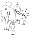
- Figure 2 is an assembled partial view of the nozzle which is shown in Figure 1 in combination with the conventional material emitter which is also shown in Figure 1;
- Figure 3 is a side sectional view of the nozzle and material emitter combination which is shown in Figure 2 and further showing the selective emission of a streaming sheet of material;
- Figure 4 is a perspective view of the combination which is shown in Figure 3;
- Figure 5 is a perspective view of a nozzle assembly which is made in accordance with the teachings of a second embodiment of the invention;
- Figure 6 is a perspective view of a nozzle which is made in accordance with the teachings of a third embodiment of the invention;
- Figure 7 is a perspective view of a nozzle which is made in accordance with the teachings of a fourth embodiment of the invention;
- Figure 8 is a perspective view of a nozzle which is made in accordance with the teachings of a fifth embodiment of the invention; and
- Figure 9 is a perspective view of a nozzle which is made in accordance with the teachings of a sixth embodiment of the invention.
-
- Referring now to Figures 1-4, there is shown a
nozzle 10 which is made in accordance with the teachings of the preferred embodiment of the invention. Particularly,nozzle 10 is substantially hollow and is preferably of a "uni-body" or "uni-member" design and is adapted for use with a conventional material emitter or "gun" 12 having a pressurisedmaterial outlet aperture 14 which extends through and is formed within a generallyrectangular flange portion 16. Other types and/or shapes ofapertures 14 andflange portions 16 may be utilised. Moreover, other types of material emitters may similarly be utilised in a manner consistent with the teachings of the preferred embodiment of the invention. - Particularly,
nozzle 10 includes afirst inlet aperture 18 which may be of any desired shape and/or size and which is selectively and communicatively coupled to and which operatively overlays the pressurisedmaterial outlet aperture 14. Particularly, theflange portion 16 is selectively and removably received withinopposed notches nozzle 10, thereby removably securingnozzle 10 to member or "gun" 12. Other methods and/or techniques of removably securingnozzle 10 toemitter 12 may be utilised and, in other alternate non-limiting embodiments of the invention,nozzle 12 may be integrally formed withinemitter 12. -
Nozzle 10 further includes and/or forms anoutlet aperture 24 which may be of a selected size and shape and amaterial reception cavity 26 which communicates withapertures material 28 is communicated tocavity 26, through theinlet aperture 18, by thematerial emitter 14. Thematerial 28 traversescavity 26 and exits thenozzle 10 through theoutlet aperture 24, in accordance with the principles and the teachings of the invention. In a further non-limiting embodiment,nozzle 10 or selected portions ofnozzle 10 may be formed by a silicon micro-machining process. - In the preferred embodiment of the invention, the
outlet aperture 24 comprises a generally rectangular shape which causes the emittedmaterial 28 to form a substantiallystreaming sheet 30 which allows for the selective placement ofmaterial 28 upon a targeted location and/or object and which further allows for the creation of substantially "sharp", "crisp", "straight", and aesthetically pleasing edges. - In a second embodiment of the invention, as best shown in Figure 6, the
outlet aperture 24 is substantially "diamond shaped" (i.e., having substantially identicaltapered end portions 25, 27), and in a third embodiment of the invention, as best shown in Figure 7, theoutlet aperture 24 is substantially "hour-glass" or "bow tie" shaped (i.e., having a relatively constricted middle orcentral portion 30 and substantially identical expandedend portions 31, 33). In yet a fourth embodiment of the invention, as best shown in Figure 8, theoutlet aperture 24 is substantially oval in shape and/or is substantially similar to the shape which is shown in Figure 1 but having substantially similarrounded end portions streaming sheet 30 ofmaterial 28 to be selectively generated. - In yet another non-limiting embodiment of the invention, which is shown best in Figure 9, the
outlet aperture 24 is substantially "barbell" shaped. In this embodiment,aperture 24 has a substantially rectangular first or central/middle portion 70 which integrally terminates within and/or forms substantially identical and generally roundedopposed end portions material 28 is inversely proportion to the width of theaperture 24. An increase of the surface tension of the emittedmaterial 28 tends to make the sheet coalesce or collapse. Hence, the flaredend portions material 28 along theouter edges sheet 30 ofmaterial 28. - As should be appreciated by those of ordinary skill in the art, that each of these various and previously delineated embodiments of
aperture 24, as shown in Figures 1 and 6-9, require thataperture 24 be continuous and substantially "uninterrupted". That is, a turbulent sheet ofmaterial 30 may be achieved by the use of several or an array of generally circular material emission apertures. However, these generally circular emission apertures form "gaps" and distortion along and/or at their respective abutting and/or interfacing edges, thereby undesirably distorting and/or creating the turbulence within the selectively formed sheet of material and undesirably preventing the creation of a steaming sheet of material. The continuous and substantially "uninterrupted" nature of theaperture 24, in all of the previously delineated embodiments, therefore substantially eliminates this turbulence drawback and desirably allows a streaming sheet of material to be formed. - In another non-limiting embodiment of the invention, as best shown in Figure 5, a pair of
nozzles emitter member 58, and eachemitter material Member 58 causesemitters nozzles 50, 52 (which may each form one of the previously delineated nozzles 10), form respectivecoloured strips object 68. In yet another alternate embodiment of the invention, the movement of the material emitters 54, 56 may occur by and/or under computer control. - In yet another non-limiting embodiment, which is best shown in Figures 1, 2, and 4, the
sidewalls portion 103 of thesidewalls nozzle 10 converge or taper along a direction beginning at theinlet aperture 18 and ending at and/or within theoutlet aperture 24. A similar convergence of the top andbottom walls sheet 30 to maintain a desired amount of surface tension, thereby substantially preventing the collapse and/or dispersion of thesheet 30 before thesheet 30 impinges upon a target location and/or object.
Claims (10)
- A nozzle having an inlet aperture (18) which receives material and a single outlet aperture (24) which communicates with said inlet aperture and which is of a certain shape which causes said material to form a streaming sheet.
- A nozzle as claimed in claim 1, wherein said certain shape comprises a rectangular shape, an oval shape, an hourglass shape, a diamond shape a barbell shape.
- A nozzle as claimed in claim 1, wherein said material comprises paint.
- A nozzle as claimed in claim 1, wherein said nozzle includes a pair of converging sidewalls.
- A nozzle as claimed in claim 4, wherein said nozzle includes converging top and bottom walls.
- A nozzle having an inlet aperture which selectively receives material and a continuous material emission portion which communicates with said inlet aperture and which is of a certain shape, effective to cause said received material to form a streaming sheet.
- A nozzle assembly comprising a first nozzle which receives a first material and which includes a continuous material outlet aperture which causes said received first material to be emitted in the form of a first streaming sheet; and a second nozzle which receives a second material and which include a second continuous material outlet aperture which causes said received second material to be emitted in the form of a second streaming sheet.
- A nozzle assembly as claimed in claim 7, wherein said first and said second materials each comprise paint.
- A nozzle assembly as claimed in claim 7, wherein said first continuous material outlet aperture and said second continuous material outlet aperture have substantially similar shapes.
- A nozzle assembly as claimed in claim 9, wherein said substantially similar shapes each comprises a rectangular shape.
Applications Claiming Priority (2)
| Application Number | Priority Date | Filing Date | Title |
|---|---|---|---|
| US470135 | 1999-12-22 | ||
| US09/470,135 US6394369B2 (en) | 1999-12-22 | 1999-12-22 | Nozzle |
Publications (2)
| Publication Number | Publication Date |
|---|---|
| EP1110616A2 true EP1110616A2 (en) | 2001-06-27 |
| EP1110616A3 EP1110616A3 (en) | 2003-11-26 |
Family
ID=23866413
Family Applications (1)
| Application Number | Title | Priority Date | Filing Date |
|---|---|---|---|
| EP00311453A Withdrawn EP1110616A3 (en) | 1999-12-22 | 2000-12-20 | Nozzle |
Country Status (3)
| Country | Link |
|---|---|
| US (1) | US6394369B2 (en) |
| EP (1) | EP1110616A3 (en) |
| CA (1) | CA2329450A1 (en) |
Cited By (3)
| Publication number | Priority date | Publication date | Assignee | Title |
|---|---|---|---|---|
| EP2345501A1 (en) * | 2010-01-12 | 2011-07-20 | Rolls-Royce plc | Spray nozzle |
| EP2495050A1 (en) * | 2011-03-03 | 2012-09-05 | Artur Schambach Lehren- und Werkzeugbau GmbH | Application nozzle for applying paste media for fine sealing clinch seams |
| ITPR20120014A1 (en) * | 2012-03-22 | 2013-09-23 | Velo Karameto | EQUIPMENT FOR SPREADING JUICE ON HAMS, SHOULDERS OR OTHER CURED MEATS |
Families Citing this family (21)
| Publication number | Priority date | Publication date | Assignee | Title |
|---|---|---|---|---|
| US6345776B1 (en) * | 1999-12-23 | 2002-02-12 | Fomo Products Inc. | Two-component dispensing gun |
| GB2372718B (en) * | 2001-01-04 | 2004-07-14 | Workinter Ltd | Nozzle intended for the concentrated distribution of a fluid for scouring of surfaces |
| JP3957640B2 (en) * | 2002-02-21 | 2007-08-15 | アイシン化工株式会社 | Wide slit nozzle and coating method with wide slit nozzle |
| JP2004009257A (en) * | 2002-06-10 | 2004-01-15 | Macoho Co Ltd | Peening treatment method |
| US7270711B2 (en) * | 2004-06-07 | 2007-09-18 | Kastalon, Inc. | Nozzle for use in rotational casting apparatus |
| US7041171B2 (en) * | 2003-09-10 | 2006-05-09 | Kastalon, Inc. | Nozzle for use in rotational casting apparatus |
| US6989061B2 (en) * | 2003-08-22 | 2006-01-24 | Kastalon, Inc. | Nozzle for use in rotational casting apparatus |
| JP4593947B2 (en) * | 2004-03-19 | 2010-12-08 | キヤノン株式会社 | Film forming apparatus and film forming method |
| US20080011491A1 (en) * | 2005-08-22 | 2008-01-17 | Victaulic Company Of America | Sprinkler having non-round exit orifice |
| US7938339B2 (en) * | 2007-11-02 | 2011-05-10 | Steris Inc. | Nozzle assembly for a washer |
| JP5275719B2 (en) * | 2008-08-05 | 2013-08-28 | ホシザキ電機株式会社 | Ice machine sprinkler |
| EP2351502B1 (en) * | 2008-11-06 | 2016-04-06 | SS&W Japan | Foaming nozzle |
| US8875610B2 (en) * | 2010-01-20 | 2014-11-04 | Atlas Die, Llc | Die lock for die retaining board |
| US20140113536A1 (en) * | 2012-10-23 | 2014-04-24 | Visteon Global Technologies, Inc. | Zonal airflow system for a vehicle |
| DE102012024054A1 (en) * | 2012-12-10 | 2014-06-26 | Udo Tartler | Device for applying, in particular, pasty plastic to a surface |
| USD705894S1 (en) * | 2013-03-12 | 2014-05-27 | Designetics, Inc. | Fluid applicator |
| US9597703B2 (en) * | 2015-02-18 | 2017-03-21 | Lam Research Ag | Slit nozzle |
| US9968804B2 (en) * | 2016-01-14 | 2018-05-15 | Reliance Industries, Llc | Nozzle for retractable fall arrest |
| USD913418S1 (en) * | 2018-07-10 | 2021-03-16 | Nordson Corporation | Powder spray gun component |
| CN112739657B (en) * | 2018-08-10 | 2023-02-28 | 康宁公司 | Apparatus and method for manufacturing glass ribbon |
| JP1652156S (en) * | 2019-05-10 | 2020-02-03 |
Family Cites Families (29)
| Publication number | Priority date | Publication date | Assignee | Title |
|---|---|---|---|---|
| US1709167A (en) * | 1929-04-16 | Soot blower | ||
| US577362A (en) * | 1897-02-16 | Half to moses samstag | ||
| US1186117A (en) * | 1915-02-25 | 1916-06-06 | James S Moe | Nozzle for painting apparatus. |
| US1239373A (en) * | 1916-03-02 | 1917-09-04 | Cornelius D Farmer | Street-flushing nozzle. |
| US1753443A (en) * | 1927-05-31 | 1930-04-08 | John D Murray | Tip for spraying nozzles |
| US2026743A (en) * | 1934-11-26 | 1936-01-07 | Clinton J Kurtz | Spray nozzle |
| US2561443A (en) * | 1950-02-24 | 1951-07-24 | March Hanna | Steaming apparatus |
| US2810608A (en) * | 1953-07-07 | 1957-10-22 | Gulf Research Development Co | Nozzle for applying cutting fluid in a flat stream |
| US2945739A (en) * | 1955-06-23 | 1960-07-19 | Du Pont | Process of melt spinning |
| NL290138A (en) * | 1962-03-14 | |||
| BE675381A (en) * | 1965-01-20 | 1966-05-16 | ||
| US3474746A (en) * | 1967-03-23 | 1969-10-28 | Kenneth S Hiniker | Flexible extension for chemical band spreader |
| US4487366A (en) * | 1981-03-12 | 1984-12-11 | Rockwell International Corporation | Porous-wall compact laser diffuser |
| US4960245A (en) * | 1983-01-17 | 1990-10-02 | Electric Power Research Institute | Casting nozzle with discharge slot defined by refractory inserts |
| GB2152847A (en) * | 1983-12-23 | 1985-08-14 | Gordon Stewart Partington | Sprayer nozzle |
| US5017409A (en) * | 1988-06-13 | 1991-05-21 | Union Carbide Chemicals And Plastics Technology Corporation | Method of conformal coating |
| AU2934592A (en) * | 1991-10-30 | 1993-06-07 | New Tech Industrial Products, Inc. | Multiple effect applicator and method |
| US5284554A (en) | 1992-01-09 | 1994-02-08 | International Business Machines Corporation | Electrochemical micromachining tool and process for through-mask patterning of thin metallic films supported by non-conducting or poorly conducting surfaces |
| US5445185A (en) | 1993-04-05 | 1995-08-29 | Ford Motor Company | Piezoelectric fluid control valve |
| US5545073A (en) | 1993-04-05 | 1996-08-13 | Ford Motor Company | Silicon micromachined CO2 cleaning nozzle and method |
| US5679062A (en) | 1995-05-05 | 1997-10-21 | Ford Motor Company | CO2 cleaning nozzle and method with enhanced mixing zones |
| US5836150A (en) | 1995-05-31 | 1998-11-17 | The United States Of America As Represented By The United States Department Of Energy | Micro thrust and heat generator |
| US5815181A (en) | 1995-06-28 | 1998-09-29 | Canon Kabushiki Kaisha | Micromachine, liquid jet recording head using such micromachine, and liquid jet recording apparatus having such liquid jet recording headmounted thereon |
| JP3377146B2 (en) * | 1995-07-24 | 2003-02-17 | ニチハ株式会社 | Multi-color coating method for building boards using spray coating equipment |
| GB9605569D0 (en) * | 1996-03-16 | 1996-05-15 | Reckitt & Colman Inc | Improved packaging |
| US5901908A (en) | 1996-11-27 | 1999-05-11 | Ford Motor Company | Spray nozzle for fluid deposition |
| US5920013A (en) | 1997-02-07 | 1999-07-06 | Ford Motor Company | Silicon micromachine with sacrificial pedestal |
| JP3896653B2 (en) * | 1997-10-08 | 2007-03-22 | トヨタ自動車株式会社 | Fuel injection valve for internal combustion engine |
| US6013315A (en) * | 1998-01-22 | 2000-01-11 | Applied Materials, Inc. | Dispense nozzle design and dispense method |
-
1999
- 1999-12-22 US US09/470,135 patent/US6394369B2/en not_active Expired - Fee Related
-
2000
- 2000-12-20 EP EP00311453A patent/EP1110616A3/en not_active Withdrawn
- 2000-12-21 CA CA002329450A patent/CA2329450A1/en not_active Abandoned
Non-Patent Citations (1)
| Title |
|---|
| None |
Cited By (3)
| Publication number | Priority date | Publication date | Assignee | Title |
|---|---|---|---|---|
| EP2345501A1 (en) * | 2010-01-12 | 2011-07-20 | Rolls-Royce plc | Spray nozzle |
| EP2495050A1 (en) * | 2011-03-03 | 2012-09-05 | Artur Schambach Lehren- und Werkzeugbau GmbH | Application nozzle for applying paste media for fine sealing clinch seams |
| ITPR20120014A1 (en) * | 2012-03-22 | 2013-09-23 | Velo Karameto | EQUIPMENT FOR SPREADING JUICE ON HAMS, SHOULDERS OR OTHER CURED MEATS |
Also Published As
| Publication number | Publication date |
|---|---|
| CA2329450A1 (en) | 2001-06-22 |
| EP1110616A3 (en) | 2003-11-26 |
| US20010030250A1 (en) | 2001-10-18 |
| US6394369B2 (en) | 2002-05-28 |
Similar Documents
| Publication | Publication Date | Title |
|---|---|---|
| US6394369B2 (en) | Nozzle | |
| EP1118387B1 (en) | Nozzle assembly | |
| EP0714708B1 (en) | Foamer nozzle assembly for trigger sprayer | |
| US4074861A (en) | Spray pattern control structure and method | |
| JP6388601B2 (en) | Method and apparatus for spraying on the ground surface | |
| US5848752A (en) | Foam aeration nozzle | |
| DE69116339T2 (en) | FOAM NOZZLE TO APPLY ON A SPRAYER | |
| EP0136132B1 (en) | Multi-orifice airless spray nozzle | |
| JPH06304501A (en) | Air addition type atomizing device suitable for coating | |
| US4504014A (en) | Device for atomizing a liquid | |
| EP1242191B1 (en) | Spray nozzle with uniform deposition concentration and velocity profile | |
| JP4397608B2 (en) | Spray nozzle | |
| JP2004033821A (en) | Spray nozzle | |
| TW313012U (en) | Foamer nozzle with looped rib flow disrupters | |
| CA2266247A1 (en) | An improved design of the nozzle arrangement on the spray tube of the conventional, oscillating lawn or hose sprinkler | |
| US6851623B1 (en) | Water spray nozzle ring for and the application of spray-on fireproofing | |
| NZ216574A (en) | Spray nozzle: spray atomised by interaction of air foil and gas stream | |
| JPH0448823Y2 (en) | ||
| EP0525998A1 (en) | Painting air brush | |
| JPS646925Y2 (en) | ||
| JPH0356101B2 (en) | ||
| JPH051064B2 (en) | ||
| JPH0798165B2 (en) | Distribution-controlled fan-shaped spray nozzle | |
| WO1989006495A1 (en) | A device for decorating an article of confectionary | |
| JPH0448825Y2 (en) |
Legal Events
| Date | Code | Title | Description |
|---|---|---|---|
| PUAI | Public reference made under article 153(3) epc to a published international application that has entered the european phase |
Free format text: ORIGINAL CODE: 0009012 |
|
| AK | Designated contracting states |
Kind code of ref document: A2 Designated state(s): AT BE CH CY DE DK ES FI FR GB GR IE IT LI LU MC NL PT SE TR |
|
| AX | Request for extension of the european patent |
Free format text: AL;LT;LV;MK;RO;SI |
|
| PUAL | Search report despatched |
Free format text: ORIGINAL CODE: 0009013 |
|
| AK | Designated contracting states |
Kind code of ref document: A3 Designated state(s): AT BE CH CY DE DK ES FI FR GB GR IE IT LI LU MC NL PT SE TR |
|
| AX | Request for extension of the european patent |
Extension state: AL LT LV MK RO SI |
|
| RIC1 | Information provided on ipc code assigned before grant |
Ipc: 7B 05C 5/02 B Ipc: 7B 05B 1/04 A |
|
| 17P | Request for examination filed |
Effective date: 20040408 |
|
| AKX | Designation fees paid |
Designated state(s): DE FR GB |
|
| STAA | Information on the status of an ep patent application or granted ep patent |
Free format text: STATUS: THE APPLICATION HAS BEEN WITHDRAWN |
|
| 18W | Application withdrawn |
Effective date: 20050812 |