EP1110511A1 - Medizinaltechnische Werkzeughaltevorrichtung mit Drehmomentbegrenzung und Scherkörper für eine derartige Vorrichtung - Google Patents
Medizinaltechnische Werkzeughaltevorrichtung mit Drehmomentbegrenzung und Scherkörper für eine derartige Vorrichtung Download PDFInfo
- Publication number
- EP1110511A1 EP1110511A1 EP00811131A EP00811131A EP1110511A1 EP 1110511 A1 EP1110511 A1 EP 1110511A1 EP 00811131 A EP00811131 A EP 00811131A EP 00811131 A EP00811131 A EP 00811131A EP 1110511 A1 EP1110511 A1 EP 1110511A1
- Authority
- EP
- European Patent Office
- Prior art keywords
- shear
- holding device
- medical tool
- tool holding
- receiving device
- Prior art date
- Legal status (The legal status is an assumption and is not a legal conclusion. Google has not performed a legal analysis and makes no representation as to the accuracy of the status listed.)
- Granted
Links
Images



Classifications
-
- B—PERFORMING OPERATIONS; TRANSPORTING
- B25—HAND TOOLS; PORTABLE POWER-DRIVEN TOOLS; MANIPULATORS
- B25B—TOOLS OR BENCH DEVICES NOT OTHERWISE PROVIDED FOR, FOR FASTENING, CONNECTING, DISENGAGING, OR HOLDING
- B25B23/00—Details of, or accessories for, spanners, wrenches, screwdrivers
- B25B23/14—Arrangement of torque limiters or torque indicators in wrenches or screwdrivers
- B25B23/1415—Break members; Arrangements specially adapted for break-bolts
-
- A—HUMAN NECESSITIES
- A61—MEDICAL OR VETERINARY SCIENCE; HYGIENE
- A61B—DIAGNOSIS; SURGERY; IDENTIFICATION
- A61B17/00—Surgical instruments, devices or methods
- A61B17/56—Surgical instruments or methods for treatment of bones or joints; Devices specially adapted therefor
- A61B17/58—Surgical instruments or methods for treatment of bones or joints; Devices specially adapted therefor for osteosynthesis, e.g. bone plates, screws or setting implements
- A61B17/88—Osteosynthesis instruments; Methods or means for implanting or extracting internal or external fixation devices
- A61B17/8875—Screwdrivers, spanners or wrenches
-
- A—HUMAN NECESSITIES
- A61—MEDICAL OR VETERINARY SCIENCE; HYGIENE
- A61B—DIAGNOSIS; SURGERY; IDENTIFICATION
- A61B90/00—Instruments, implements or accessories specially adapted for surgery or diagnosis and not covered by any of the groups A61B1/00 - A61B50/00, e.g. for luxation treatment or for protecting wound edges
- A61B90/03—Automatic limiting or abutting means, e.g. for safety
- A61B2090/031—Automatic limiting or abutting means, e.g. for safety torque limiting
Definitions
- the invention relates to a medical tool holding device Torque limitation according to the preamble of claim 1. Die The invention further relates to a shear body for a medical technology Tool holder with torque limitation according to The preamble of claim 14. The invention further relates to a kit for a medical tool holding device with Torque limitation according to the preamble of claim 19.
- the sub-claims 2 to 12 relate to further, advantageous configurations of medical technology Tool holders with torque limitation.
- the task is further solved with one for use in the invention medical tool holding device adapted Shear body according to claim 14.
- the sub-claims 15 to 18 relate to further, advantageously designed shear bodies.
- a medical technology Tool holder with torque limitation comprising a Receiving device for at least one shear body and one rotatable with the receiving device connected shear means, which with respect to a shaving body located in the receiving device is that the shear is applied to the shear body, at least when a Torque acts on the shear, the shear and the Shear bodies are designed and arranged so that they are mutually adapted, that when a certain torque is exceeded, the shear means at least partially severed the shear body.
- the medical tool holding device is shown in a preferred embodiment on one side with a handle and connected on the other side with a tool and forms like this a medical-technical, for example a surgical instrument.
- the handle is elongated and defines a longitudinal axis around which the instrument together with the Tool is rotated, being between the handle and tool arranged tool holder the maximum to be transferred Torque limited.
- the handle can also be designed as a T-handle.
- the medical tool holding device has the advantage that the maximum transferable torque by the Use of a shaving body in combination with a relative shear agent is exactly definable.
- the shear body is affected by the action of the Scherffens destroyed and must be used after the Tool holder to be replaced.
- the shear means has one low wear and can also be replaced if necessary.
- the medical tool holding device according to the invention has hence the advantage that the maximum transferable torque too over a relatively large period of, for example, one year or reproducible even for several years. Besides, there is no Tool holder calibration required.
- the inventive design has an advantageous embodiment Tool holding device a receiving device for a plurality of Shear bodies on, for example, a cradle for six Shaving body, so that several times in succession when the certain torque of the shear body is cut, the However, shear bodies are only to be replaced when everyone is in the Tool holder device located shear body are destroyed.
- the medical tool holding device allows for example a screw like a stud or a Bone screw during implantation with an exact tighten the preset torque.
- a suitable combination of these parameters can be used Variety of different and exactly reproducible maximum Achieve torques.
- these shear bodies have a color coding, with shaving bodies with the same color the same result in maximum torque.
- the inventive Tool holding device thus has the advantage that the maximum achievable torque widely using the same device Limits is variable, depending on the maximum required Torque a corresponding shear body in the receiving device is inserted.
- the maximum allowed torque depend, for example, on the size of the selected implant.
- the Tool holding device according to the invention enables one Surgeons or an assistant during an operation the maximum Adjust the torque of the instrument by the appropriate Shear body can be inserted into the receiving device. Commitment different shaving bodies must be available in sterilized form.
- a surgical instrument comprising the invention Medical tool holding device can, for example, as a Torque limiting screwdriver be designed.
- the medical tool holding device according to the invention is shown in a preferred embodiment made of sterilizable material, in particular Metal made so that the device after surgery Sheared bodies are removed, the device is sterilized, and then can be used for further operations.
- the tool holding device according to the invention can be used for different trigger moments can be put together without the outer geometry of the tool holder or the shear pin to change.
- the tool holding device according to the invention can under Taking into account the required triggering torque in a modular manner be compiled so that with few changes, for example a replacement of a single blade by a double blade, or by the Using a pointed or blunt blade, an instrument with the desired triggering moment is available.
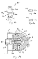
- FIG. 1a shows the side view of a surgical instrument 1 comprising a medical tool holding device 2 with Torque limitation.
- the tool holding device 2 comprises one Receiving device 5, which also forms a first partial housing second sub-housing 6 and one in the receiving device 5 by one common longitudinal axis L rotatably mounted shaft 10, the shaft 10 has a receptacle for a tool 4.
- a handle 3 extending in the direction of the longitudinal axis L is attached.
- On the shaft 10 is the detachable, in the direction of the longitudinal axis L. extending tool 4 attached, at the tip 4a a hexagon Grasping a hexagon screw is arranged.
- Fig. 1b shows in cross section along the section line A-A the internal structure of the tool holding device 2.
- the holding device 5 comprises one Holding device 5b with six regularly distributed over the circumference arranged holding openings 5c, in each of which a cylindrical configured shear body 7 is arranged.
- One towards the The longitudinal axis L extending shaft 10 has a with respect to the longitudinal axis L.
- radially protruding shear means 10a The shaft 10 and the shear means 10a can be rotated about the longitudinal axis L in the receiving device 5 stored.
- the shear means 10a and the shear body 7 are mutually such arranged that the shear means 10a between the shear bodies 7 and is hindered with respect to a rotational movement in the relative direction of rotation 10e.
- the shear body 7, on which the shear means 10a rests is severed therefrom. Therefore can be screwed into the instrument 1 while tightening Screw does not exceed a predetermined maximum torque become.
- the instrument 1 shown allows a maximum of six screws to tighten one after the other with a certain torque. Every time when the specific torque is reached, a single shear body 7 severed so that after six such operations all shear bodies 7 are severed and need to be replaced.
- the longitudinal section shown in Fig. 1c through the instrument 1 along the Line B-B shows the receiving device 5 with arranged therein Shaving bodies 7.
- the receiving device 5 is fixed with the handle 3 connected.
- the shaft 10 and Shaft lock 11 rotatably supported via a ball bearing 12, the Shaft 10 and the shaft lock 11 from a lock screw 9 are held together.
- the tool 4 is detachable, for example pluggable or screwable, connected to the shaft 10.
- the partial housing 6 is in Movable in the longitudinal direction L and via a connection, for example a snap connection, firmly connected to the receiving device 5.
- the partial housing 6 is partially on the outer surface 5a Receiving device 5 slipped over and encloses the of the Receiving device 5, the shaft 10 and the partial housing 6 formed Inner space.
- This interior is preferably sealed from the outside, by between the partial housing 6 and the shaft 10 or a seal is formed between the shaft 10 and the tool 4, so that no liquid, especially no water or blood, in the Interior can penetrate. Likewise, no one who is possibly loose can Object inside reach outside.
- Fig. 2a shows an exploded view of the individual components of the Instrumentes 1 in detail.
- the instrument 1 consists of the tool 4, the handle 3 and the medical technology connecting these two Tool holding device 2, which the receiving device 5 with Holding device 5b, shaft 10 with shaft lock 11 and ball bearing 12, and includes a partial housing 6.
- the conceived as consumables Shaving bodies 7 can be inserted into the holding device 5b.
- Fig. 2b shows an embodiment of a closure device around the Receiving device 5 and the second sub-housing 6 releasably fixed to each other connect to.
- the receiving device 5 has a cylindrical part 5a with a smooth surface on which a pin 5e in relation to the part 5a radial direction is arranged above.
- the second sub-housing 6 has a recess 6c adapted to the arrangement of the pin 5e on.
- One attached to the surface of the second sub-case 6 Mark 6b represents the movements required to move the parts 5,6 to connect or disconnect.
- the Cradle 5 rotated in the "lock” direction until the pin 5e in the Fig. 2b is the position shown. In this position they are Recording device 5 and the second sub-housing 6 and the Holding blades 6a are in engagement with the shear pins 7.
- the marking "open” comprises two directions perpendicular to each other. To the To release the connection device 5 is initially in the direction “open” rotated and then the second housing part 6 in the "open” direction subtracted (perpendicular to the direction of rotation). From Fig. 2b it can be seen that a slight twisting of the receiving device 5 in the "open” direction is sufficient to remove the pin 5e from the recess 6c.
- FIG. 3a shows the one-piece shaft 10 with the upper shaft part 10b, lower shaft part 10c and the above shear means 10a in detail.
- the upper shaft part 10b is the Shear means 10a and its blade 10d can be seen.
- the side view according to 3c shows the shaft 10 running in the longitudinal direction L with the upper one Shaft part 10b and lower shaft part 10c.
- the shear means 10a is along the line C-C shown cut and shows a flat, blade extending at an angle ⁇ with respect to the longitudinal axis L. 10d.
- the blade 10d can also be in a Numerous other geometric shapes can be designed, and for example, as shown in a section in FIGS. 3d and 3e, have a partially rounded or elliptical cutting surface.
- FIG. 4 shows a perspective view of the receiving device 5 with External thread 5a, holding device 5b with holding openings 5c for the Shaving body 7 and an outer housing 5d.
- cylindrical shear body 7 or shear pins 7 can can be used individually in the receiving device 5. There are only so many Use shear body 7 as needed.
- the shear body 7 inserted into the receiving device 5 then the sub-housing 6 in Longitudinal direction L moves until it is slipped over the surface 5a. Thereupon the partial housing 6 is rotated slightly in the direction 10e until the partial housing 6 snaps into a not shown locking device and thereby firmly in whose location is kept.
- the housing 6 comprises six over the circumference distributed, radially inwardly projecting holding blades 6a, which when turning in the direction 10e penetrate into the shear body 7 and this in fix their position. This ensures that the shear body 7 not free in the interior of the tool during use Move the torque limiting device 2.
- the shear body 7 is only partially formed by the shear means 10a severed so that no loose, especially none, due to the shear effect larger loose parts are generated.
- shearing means 7b shows a further exemplary embodiment of a shearing means 7b, which consists of six firmly connected to each other via a retaining ring 7a Shear bodies 7 there.
- the entire shearing means 7b is one Handle can be used in the receiving device 5.
- the shear 7b could also be designed such that the shear body 7 is only slightly or are not connected to the retaining ring 7a at all.
- FIG. 5 shows the relationship between the angle ⁇ of the blade 10d of the shear means 10a shown in FIG. 3c and the resulting maximum torque for a specific material and for a specific geometric configuration of a shear body 7.
- the maximum torque can be set relatively precisely by an appropriate choice of the angle ⁇ .
- a plurality of shafts 10 with blades 10d of different angles ⁇ can be available in a kit for the tool 1, so that the blade 10d required to achieve a desired maximum torque can be inserted into the receiving device 5.
- the maximum torque can be varied in that different shear bodies 7 are available for inserting the holding device 5, these shear bodies 7 being made, for example, of different materials, or have a different density or geometry.
- further possibilities for influencing the maximum torque are to vary the radial length R2 of the shear means 10a and / or to use several shear means 10a at the same time.
- the radial length R2 is less than the distance R1 of the center of the shear body 7 from the center of rotation of the shear means 10a. The shear body 7 is therefore only partially severed by the shear means 10a.
- Shear means 10a could be configured with one blade 10d, or as shown in FIG. 6 with two blades 10d, or for example with three blades 10d.
- the following maximum torques could be achieved, for example, by correspondingly varying the number of blades 10d: Relationship between number of blades and maximum torque Number of blades maximum torque Maximum number of uses with 6 shear pins 1 4 Nm 6 x 2 8 Nm 3 x 3rd 12 Nm 2 x
- the maximum torque can be varied by means of the shear means 10a.
- the shear means 10a preferably identical shear pins 7 are used. More different For example, maximum torque values can be read through differently designed blades 10d, or by differently designed Achieve shear pins 7.
- the shaft 10 shown in FIG. 8a has, in contrast to that in FIG. 3a Embodiment shown two oppositely arranged Shear means 10a.
- the end portion of the lower shaft part has 10c, ramp-shaped recesses distributed in the circumferential direction 10f each with a circular depression 10g.
- FIG. 8b shows a further exemplary embodiment of a Tool holder.
- the same reference numerals denote in the Figures 1c and 8b the same items.
- the section shown is the section in FIG. 8b such that it does not through the shear pins 7 but runs completely through the metallic Pick-up device 5.
- shear pins 7 are not shown in Fig. 8b.
- the shaft 10 is as configured in Fig. 8a.
- One in the cradle 5 springs arranged pin 5f presses with its tip into the ramp-shaped Recess 10f or in the circular recess 10g and thereby causes in one direction of rotation a freewheel.
- Fig. 9a shows a plan view of a holding device 13 for shear pins 7.
- Die Holding device 13 has a circular support 13a with two tabs 13e, with the carrier 13a being evenly spaced in the circumferential direction six recesses 13d are arranged.
- Each recess 13d has a bore 13b with a smaller diameter, and in the circumferential direction arranged offset a bore 13c with a larger diameter.
- 9b shows a section through the holding device 13 along the line C-C.
- 9c shows a perspective view of the holding device 13.
- FIG. 11 shows a holding device 13 with six shear pins inserted 7.
- shear pins 7 To attach the shear pins 7 in the holding device 13 these are initially inserted into the larger diameter bore 13c, and then shifted towards the smaller diameter bore 13b, so that there is a press fit and the shear pin 7 is held thereby.
- in the holding device 13 arranged.
- the shear pins 7 held in this way are then together in the respective holding openings 5c of the receiving device 5 introduced.
- the holding device 13 with respect to the Cradle 5 slightly rotated so that the clamp seat is released, by the bore 13c with a larger diameter the shear pins 7 surrounds.
- the holding means 13 can now be lifted off, the Shear pins 7 remain in the holding openings 5c.
Landscapes
- Health & Medical Sciences (AREA)
- Engineering & Computer Science (AREA)
- Orthopedic Medicine & Surgery (AREA)
- Surgery (AREA)
- Life Sciences & Earth Sciences (AREA)
- Medical Informatics (AREA)
- Biomedical Technology (AREA)
- Heart & Thoracic Surgery (AREA)
- Nuclear Medicine, Radiotherapy & Molecular Imaging (AREA)
- Molecular Biology (AREA)
- Animal Behavior & Ethology (AREA)
- General Health & Medical Sciences (AREA)
- Public Health (AREA)
- Veterinary Medicine (AREA)
- Mechanical Engineering (AREA)
- Dental Tools And Instruments Or Auxiliary Dental Instruments (AREA)
- Surgical Instruments (AREA)
Abstract
Description
- die Materialeigenschaften des Scherkörpers,
- die geometrische Ausgestaltung des Scherkörpers,
- die geometrische Ausgestaltung des Schermittels, wobei das Schermittel vorzugsweise eine Klinge aufweist, deren Geometrie in einer Vielzahl von Formgebungen ausgestaltbar ist,
- den wirksamen Hebelarm des Schermittels;
- den Grad der Durchtrennung des Scherkörpers, teilweise oder vollständig.
- Fig. 1a
- eine Seitenansicht einer medizinaltechnischen Werkzeughaltevorrichtung eingebaut in ein medizinaltechnisches Instrument;
- Fig. 1b
- ein Querschnitt durch die Werkzeughaltevorrichtung gemäss Fig. 1a entlang der Schnittlinie A-A;
- Fig. 1c
- ein Längsschnitt durch die Werkzeughaltevorrichtung gemäss Fig. 1b entlang der Schnittlinie B-B;
- Fig. 2a
- eine Explosionsdarstellung der Werkzeughaltevorrichtung;
- Fig. 2b
- eine Detailansicht des Verschlusses einer Werkzeughaltevorrichtung;
- Fig. 3a
- eine Ansicht einer Welle umfassend ein Schermittel;
- Fig. 3b
- eine Aufsicht der Welle gemäss Fig. 3a;
- Fig. 3c
- eine Seitenansicht der Welle gemäss Fig. 3b sowie ein Schnitt durch das Schermittel entlang der Schnittlinie C-C;
- Fig. 3d,3e
- ein Schnitt durch weitere Ausführungsbeispiele von Schermitteln;
- Fig. 4
- eine Ansicht einer Aufnahmevorrichtung;
- Fig. 5
- eine Darstellung des Zusammenhangs zwischen dem Winkel α der Klinge sowie dem maximal erreichbaren Drehmoment;
- Fig. 6
- ein Querschnitt entlang der Schnittlinie A-A mit einer kürzer ausgestalteten Klinge;
- Fig. 7
- ein Ring aus sechs einzelnen oder fest miteinander verbundenen Scherkörpern;
- Fig. 8a
- eine weiteres Ausführungsbeispiel einer Welle umfassend ein Schermittel sowie Ausnehmungen für eine Arretierungsvorrichtung;
- Fig. 8b
- ein Längsschnitt durch ein weiteres Ausführungsbeispiel einer Werkzeughaltevorrichtung mit einem Freilauf;
- Fig. 9a
- eine Aufsicht auf eine Haltevorrichtung für Abscherstifte;
- Fig. 9b
- ein Schnitt durch die Haltevorrichtung gemäss Fig. 9a entlang der Schnittlinie C-C;
- Fig. 9c
- eine perspektivische Ansicht der Haltevorrichtung;
- Fig. 10
- eine Seitenansicht eines Abscherstifts;
- Fig. 11
- eine perspektivische Ansicht einer Haltevorrichtung mit eingesetzten Abscherstiften.
| Zusammenhang von Anzahl Klingen und maximalem Drehmoment | ||
| Anzahl Klingen | Maximales Drehmoment | Maximale Anzahl des Gebrauchs bei 6 Abscherstiften |
| 1 | 4 Nm | 6 x |
| 2 | 8 Nm | 3 x |
| 3 | 12 Nm | 2 x |
Claims (22)
- Medizinaltechnische Werkzeughaltevorrichtung (2) mit Drehmomentbegrenzung, umfassend eine Aufnahmevorrichtung (5) zum Halten zumindest eines Scherkörpers (7) sowie ein rotierbar mit der Aufnahmevorrichtung (5) verbundenes Schermittel (10a), wobei das Schermittel (10a) und die Aufnahmevorrichtung (5) derart gegenseitig angepasst ausgestaltet sind, dass das Schermittel (10a) an einem gehaltenen Scherkörper (7) anliegt, zumindest wenn ein Drehmoment auf das Schermittel (10a) wirkt, dass das Schermittel (10a) zumindest eine Klinge (10d) aufweist, dass die Klingen (10d) derart angeordnet ist, dass sie auf den Scherkörper (7) einwirken, und dass beim Überschreiten eines bestimmten Drehmomentes das Schermittel (10a) den Scherkörper (7) zumindest teilweise durchtrennt.
- Medizinaltechnische Werkzeughaltevorrichtung (2) nach Anspruch 1, dadurch gekennzeichnet, dass die Aufnahmevorrichtung (5) mit einem Handgriff (3) und das Schermittel (10a) mit einem Werkzeug (4) verbindbar ist, oder dass die Aufnahmevorrichtung (5) mit dem Werkzeug (4) und das Schermittel (10a) mit dem Handgriff (3) verbindbar ist.
- Medizinaltechnische Werkzeughaltevorrichtung (2) nach einem der vorhergehenden Ansprüche, dadurch gekennzeichnet, dass der Scherkörper (7) aus einem thermoplastischen Kunststoff wie Polyethylen, UHMW-Polyethylen oder aus Metall besteht.
- Medizinaltechnische Werkzeughaltevorrichtung (2) nach einem der vorhergehenden Ansprüche, dadurch gekennzeichnet, dass die Aufnahmevorrichtung (5) zur Aufnahme einer Mehrzahl von Scherkörpern (7), insbesondere sechs Scherkörpern (7), ausgestaltet ist.
- Medizinaltechnische Werkzeughaltevorrichtung (2) nach einem der vorhergehenden Ansprüche, dadurch gekennzeichnet, dass die Aufnahmevorrichtung (5) zusammen mit einem abnehmbaren Gehäuseteil (6) einen Hohlraum bildet, innerhalb welchem das Schermittel (10a) und der Scherkörper (7) angeordnet sind.
- Medizinaltechnische Werkzeughaltevorrichtung (2) nach Anspruch 5, dadurch gekennzeichnet, dass das abnehmbare Gehäuseteil (6) auf dessen Innenseite angeordnete Haltemittel (6a) aufweist, welche zum Halten der Scherkörper (7) bestimmt sind.
- Medizinaltechnische Werkzeughaltevorrichtung (2) nach einem der vorhergehenden Ansprüche, dadurch gekennzeichnet, dass das Schermittel (10a) mit einer um eine Drehachse (10f) drehbar gelagerte Welle (10) fest verbunden ist.
- Medizinaltechnische Werkzeughaltevorrichtung (2) nach Anspruch 7, dadurch gekennzeichnet, dass die Klinge (10d) einen bezüglich der Drehachse (10f) um einen Winkel α geneigten Verlauf aufweist, wobei der Wert des Winkels α insbesondere zwischen 0 Grad und 89 Grad liegt.
- Medizinaltechnische Werkzeughaltevorrichtung (2) nach einem der vorhergehenden Ansprüche, dadurch gekennzeichnet, dass die Klinge (10d) eine zumindest teilweise gerundete Schneidfläche aufweist.
- Medizinaltechnische Werkzeughaltevorrichtung (2) nach Anspruch 8 oder 9 umfassend eine Klinge (10d) deren radial zur Drehachse (10f) verlaufende Länge zwischen 5mm und 20mm beträgt.
- Medizinaltechnische Werkzeughaltevorrichtung (2) nach einem der vorhergehenden Ansprüche, dadurch gekennzeichnet, dass zumindest die Aufnahmevorrichtung (5) sowie der Scherkörper (7), vorzugsweise auch das Werkzeug (4) sowie der Handgriff (3), aus einem sterilisierbaren Material bestehen.
- Medizinaltechnische Werkzeughaltevorrichtung (2) nach einem der vorhergehenden Ansprüche, dadurch gekennzeichnet, dass diese einen Freilauf umfasst, welcher derart ausgebildet ist, dass das Schermittel (10a) in der einen Drehrichtung bezüglich der Aufnahmevorrichtung (5) drehbar gelagert ist, und dass das Schermittel (10a) in der entgegengesetzten Drehrichtung bezüglich der Aufnahmevorrichtung (5) arretiert ist.
- Medizinaltechnisches Gerät (1) umfassend eine Werkzeughaltevorrichtung (2) nach einem der vorhergehenden Ansprüche.
- Scherkörper (7) ausgestaltet zur Verwendung in einer medizinaltechnischen Werkzeughaltevorrichtung (2) nach einem der Ansprüche 1 bis 12.
- Scherkörper (7) nach Anspruch 14, dadurch gekennzeichnet, dass der Scherkörper (7) als zylinderförmiger Körper ausgestaltet ist.
- Scherkörper (7) nach Anspruch 14 oder 15, dadurch gekennzeichnet, dass dieser eine Mehrzahl von einzelnen Scherkörpern (7) umfasst, welche miteinander verbunden sind.
- Scherkörper (7) nach einem der Ansprüche 14 bis 16, gekennzeichnet durch eine Mehrzahl von Scherkörpern (7) unterschiedlichen Materials und/oder unterschiedlicher Dichte, wobei gleich wirkende Scherkörper (7) identisch gekennzeichnet sind.
- Scherkörper (7) nach Anspruch 17, dadurch gekennzeichnet, dass diese mit Farben gekennzeichnet sind, und dass gleich wirkende Scherkörper (7) dasselbe Kennzeichen aufweisen.
- Bausatz für eine medizinaltechnische Werkzeughaltevorrichtung (2) mit Drehmomentbegrenzung nach einem der Ansprüche 1 bis 12, umfassendeine Mehrzahl von Aufnahmevorrichtungen (5) zum Halten zumindest eines Scherkörpers (7) und/oder zum Halten des Scherkörpers (7) in unterschiedlichen Abständen vom Drehzentrum,eine Mehrzahl von Scherkörpern (7) unterschiedlicher Form und/oder unterschiedlichen Materials und/oder unterschiedlicher Dichte,eine Mehrzahl von als Klingen ausgestaltete Schermittel (10a), wobei die Klingen eine unterschiedliche Länge aufweisen und/oder die Klingen (10d) bezüglich der Drehachse (10f) einen unterschiedlich geneigten Winkel α aufweisen, und wobei jedes Schermittel (10a) eine oder mehrere Klingen (10d) aufweist.
- Bausatz für eine medizinaltechnische Werkzeughaltevorrichtung (2) mit Drehmomentbegrenzung nach Anspruch 19, umfassend eine im wesentlichen kreisförmige Haltevorrichtung (13) mit einer Mehrzahl in Umfangsrichtung beabstandet angeordneter Ausnehmungen (13d), wobei der Durchmesser der Ausnehmungen (13d) derart bezüglich den Scherkörpern (7) angepasst ausgestaltet ist, dass die Scherkörper (7) in den Ausnehmungen (13d) befestigbar sind.
- Bausatz nach Anspruch 20, dadurch gekennzeichnet, dass die Ausnehmungen (13d) derart beabstandet auf der Haltevorrichtung (13) angeordnet sind, dass alle gehaltenen Scherkörper (7) gleichzeitig in die Halteöffnungen (5c) der Aufnahmevorrichtung (5) einführbar sind.
- Bausatz nach Anspruch 20 oder 21, dadurch gekennzeichnet, dass die Ausnehmung (13d) zwei kreisförmige, sich überschneidende Bohrungen (13b, 13c) mit unterschiedlichem Durchmesser umfasst, wobei die Zentren der beiden Bohrungen (13b, 13c) in Umfangsrichtung der Haltevorrichtung (13) leicht versetzt angeordnet sind.
Priority Applications (1)
| Application Number | Priority Date | Filing Date | Title |
|---|---|---|---|
| EP00811131.2A EP1110511B1 (de) | 1999-12-20 | 2000-11-28 | Medizinaltechnische Werkzeughaltevorrichtung mit Drehmomentbegrenzung |
Applications Claiming Priority (3)
| Application Number | Priority Date | Filing Date | Title |
|---|---|---|---|
| EP99811172 | 1999-12-20 | ||
| EP99811172 | 1999-12-20 | ||
| EP00811131.2A EP1110511B1 (de) | 1999-12-20 | 2000-11-28 | Medizinaltechnische Werkzeughaltevorrichtung mit Drehmomentbegrenzung |
Publications (2)
| Publication Number | Publication Date |
|---|---|
| EP1110511A1 true EP1110511A1 (de) | 2001-06-27 |
| EP1110511B1 EP1110511B1 (de) | 2014-09-17 |
Family
ID=26074085
Family Applications (1)
| Application Number | Title | Priority Date | Filing Date |
|---|---|---|---|
| EP00811131.2A Expired - Lifetime EP1110511B1 (de) | 1999-12-20 | 2000-11-28 | Medizinaltechnische Werkzeughaltevorrichtung mit Drehmomentbegrenzung |
Country Status (1)
| Country | Link |
|---|---|
| EP (1) | EP1110511B1 (de) |
Cited By (1)
| Publication number | Priority date | Publication date | Assignee | Title |
|---|---|---|---|---|
| CN114917060A (zh) * | 2022-04-21 | 2022-08-19 | 上海翰凌医疗器械有限公司 | 一种介入系统及用于介入系统的切线装置 |
Citations (3)
| Publication number | Priority date | Publication date | Assignee | Title |
|---|---|---|---|---|
| US5158458A (en) * | 1991-06-25 | 1992-10-27 | Perry William L | System for driving and tightening components in a prosthodontic restoration |
| US5347894A (en) * | 1993-05-28 | 1994-09-20 | Pmt Corporation | Torque limiting device |
| US5368480A (en) | 1993-12-08 | 1994-11-29 | Dentsply Research & Development Corp. | Dental implant wrench |
-
2000
- 2000-11-28 EP EP00811131.2A patent/EP1110511B1/de not_active Expired - Lifetime
Patent Citations (3)
| Publication number | Priority date | Publication date | Assignee | Title |
|---|---|---|---|---|
| US5158458A (en) * | 1991-06-25 | 1992-10-27 | Perry William L | System for driving and tightening components in a prosthodontic restoration |
| US5347894A (en) * | 1993-05-28 | 1994-09-20 | Pmt Corporation | Torque limiting device |
| US5368480A (en) | 1993-12-08 | 1994-11-29 | Dentsply Research & Development Corp. | Dental implant wrench |
Cited By (1)
| Publication number | Priority date | Publication date | Assignee | Title |
|---|---|---|---|---|
| CN114917060A (zh) * | 2022-04-21 | 2022-08-19 | 上海翰凌医疗器械有限公司 | 一种介入系统及用于介入系统的切线装置 |
Also Published As
| Publication number | Publication date |
|---|---|
| EP1110511B1 (de) | 2014-09-17 |
Similar Documents
| Publication | Publication Date | Title |
|---|---|---|
| EP1219266B1 (de) | Implantat zum Einsetzen zwischen Wirbelkörper sowie Operationsinstrument zur Handhabung des Implantats | |
| EP0897290B1 (de) | Chirurgischer drehmomentschlüssel | |
| DE19707373C1 (de) | Bajonettkupplung zum lösbaren Verbinden zweier Rohrschaftinstrumente oder -instrumententeile | |
| DE2811331A1 (de) | Ellenbogengelenk in form einer endovollprothese | |
| EP2706247B1 (de) | Chirurgisches Instrument, chirurgisches Handstück und chirurgisches Antriebssystem | |
| DE102004051792B4 (de) | Chirurgisches Instrument mit einstellbarem rotatorischem Schneidwerkzeug | |
| DE3640420A1 (de) | Selbstspannendes spannfutter | |
| DE9017245U1 (de) | Prothetische Lagerungsvorrichtung | |
| WO2018041984A1 (de) | Knochenklammer mit adapter für messhilfen | |
| EP3570759B1 (de) | Medizinisches instrumentarium mit sägeschablone | |
| US6358152B2 (en) | Medical/technical tool holder apparatus with torque limitation and a shear body for an apparatus of this kind | |
| EP2845554A1 (de) | Medizinisches Instrument | |
| DE102011052442B3 (de) | Ratsche und Verfahren zum Übertragen eines Drehmoments auf ein Gegenstück, sowie Verwendung einer derartigen Ratsche im Medizinbereich | |
| EP3294157A1 (de) | Chirurgisches instrument mit abstandhaltendem schwenkelement | |
| EP0931523B1 (de) | System aus einer künstlichen Gelenkkomponente und einem Instrument zur Handhabung der künstlichen Gelenkkomponente | |
| DE10301691B4 (de) | Buchsenhandgriff und Buchsensystem | |
| WO2019175136A1 (de) | Implantat | |
| EP1110511B1 (de) | Medizinaltechnische Werkzeughaltevorrichtung mit Drehmomentbegrenzung | |
| AT406013B (de) | Lösbare spannvorrichtung für ein rotierendes medizinisches oder dentales werkzeug | |
| DE202004015912U1 (de) | Knochenschraube | |
| EP3630018B1 (de) | Radiusköpfchenimplantat | |
| DE3343867A1 (de) | Vorrichtung zur loesbaren befestigung des aufsatzes eines chirurgischen instruments | |
| WO2001060272A1 (de) | Verriegelungsnagel und zielgerät | |
| EP3494912A1 (de) | Vorrichtung zum lösen von, insbesondere kaltverschweissten, schrauben in der orthopädie sowie werkzeugeinsatz | |
| DE20321716U1 (de) | Vorrichtung zum Verbinden eines Knochendeckels mit einem Schädelknochen |
Legal Events
| Date | Code | Title | Description |
|---|---|---|---|
| PUAI | Public reference made under article 153(3) epc to a published international application that has entered the european phase |
Free format text: ORIGINAL CODE: 0009012 |
|
| AK | Designated contracting states |
Kind code of ref document: A1 Designated state(s): AT BE CH CY DE DK ES FI FR GB GR IE IT LI LU MC NL PT SE TR |
|
| AX | Request for extension of the european patent |
Free format text: AL;LT;LV;MK;RO;SI |
|
| 17P | Request for examination filed |
Effective date: 20011130 |
|
| AKX | Designation fees paid |
Free format text: AT BE CH CY DE DK ES FI FR GB GR IE IT LI LU MC NL PT SE TR |
|
| RAP1 | Party data changed (applicant data changed or rights of an application transferred) |
Owner name: ZIMMER GMBH |
|
| 17Q | First examination report despatched |
Effective date: 20080926 |
|
| GRAP | Despatch of communication of intention to grant a patent |
Free format text: ORIGINAL CODE: EPIDOSNIGR1 |
|
| INTG | Intention to grant announced |
Effective date: 20140411 |
|
| GRAS | Grant fee paid |
Free format text: ORIGINAL CODE: EPIDOSNIGR3 |
|
| GRAA | (expected) grant |
Free format text: ORIGINAL CODE: 0009210 |
|
| AK | Designated contracting states |
Kind code of ref document: B1 Designated state(s): AT BE CH CY DE DK ES FI FR GB GR IE IT LI LU MC NL PT SE TR |
|
| REG | Reference to a national code |
Ref country code: GB Ref legal event code: FG4D Free format text: NOT ENGLISH |
|
| REG | Reference to a national code |
Ref country code: CH Ref legal event code: EP |
|
| REG | Reference to a national code |
Ref country code: IE Ref legal event code: FG4D Free format text: LANGUAGE OF EP DOCUMENT: GERMAN |
|
| REG | Reference to a national code |
Ref country code: AT Ref legal event code: REF Ref document number: 687317 Country of ref document: AT Kind code of ref document: T Effective date: 20141015 |
|
| REG | Reference to a national code |
Ref country code: DE Ref legal event code: R096 Ref document number: 50016385 Country of ref document: DE Effective date: 20141030 |
|
| PG25 | Lapsed in a contracting state [announced via postgrant information from national office to epo] |
Ref country code: GR Free format text: LAPSE BECAUSE OF FAILURE TO SUBMIT A TRANSLATION OF THE DESCRIPTION OR TO PAY THE FEE WITHIN THE PRESCRIBED TIME-LIMIT Effective date: 20141218 Ref country code: SE Free format text: LAPSE BECAUSE OF FAILURE TO SUBMIT A TRANSLATION OF THE DESCRIPTION OR TO PAY THE FEE WITHIN THE PRESCRIBED TIME-LIMIT Effective date: 20140917 Ref country code: FI Free format text: LAPSE BECAUSE OF FAILURE TO SUBMIT A TRANSLATION OF THE DESCRIPTION OR TO PAY THE FEE WITHIN THE PRESCRIBED TIME-LIMIT Effective date: 20140917 |
|
| REG | Reference to a national code |
Ref country code: NL Ref legal event code: VDEP Effective date: 20140917 |
|
| PG25 | Lapsed in a contracting state [announced via postgrant information from national office to epo] |
Ref country code: CY Free format text: LAPSE BECAUSE OF FAILURE TO SUBMIT A TRANSLATION OF THE DESCRIPTION OR TO PAY THE FEE WITHIN THE PRESCRIBED TIME-LIMIT Effective date: 20140917 |
|
| PG25 | Lapsed in a contracting state [announced via postgrant information from national office to epo] |
Ref country code: NL Free format text: LAPSE BECAUSE OF FAILURE TO SUBMIT A TRANSLATION OF THE DESCRIPTION OR TO PAY THE FEE WITHIN THE PRESCRIBED TIME-LIMIT Effective date: 20140917 |
|
| PG25 | Lapsed in a contracting state [announced via postgrant information from national office to epo] |
Ref country code: PT Free format text: LAPSE BECAUSE OF FAILURE TO SUBMIT A TRANSLATION OF THE DESCRIPTION OR TO PAY THE FEE WITHIN THE PRESCRIBED TIME-LIMIT Effective date: 20150119 Ref country code: ES Free format text: LAPSE BECAUSE OF FAILURE TO SUBMIT A TRANSLATION OF THE DESCRIPTION OR TO PAY THE FEE WITHIN THE PRESCRIBED TIME-LIMIT Effective date: 20140917 |
|
| REG | Reference to a national code |
Ref country code: DE Ref legal event code: R097 Ref document number: 50016385 Country of ref document: DE |
|
| PG25 | Lapsed in a contracting state [announced via postgrant information from national office to epo] |
Ref country code: MC Free format text: LAPSE BECAUSE OF FAILURE TO SUBMIT A TRANSLATION OF THE DESCRIPTION OR TO PAY THE FEE WITHIN THE PRESCRIBED TIME-LIMIT Effective date: 20140917 Ref country code: LU Free format text: LAPSE BECAUSE OF FAILURE TO SUBMIT A TRANSLATION OF THE DESCRIPTION OR TO PAY THE FEE WITHIN THE PRESCRIBED TIME-LIMIT Effective date: 20141128 Ref country code: BE Free format text: LAPSE BECAUSE OF NON-PAYMENT OF DUE FEES Effective date: 20141130 |
|
| REG | Reference to a national code |
Ref country code: CH Ref legal event code: PL |
|
| PLBE | No opposition filed within time limit |
Free format text: ORIGINAL CODE: 0009261 |
|
| STAA | Information on the status of an ep patent application or granted ep patent |
Free format text: STATUS: NO OPPOSITION FILED WITHIN TIME LIMIT |
|
| PG25 | Lapsed in a contracting state [announced via postgrant information from national office to epo] |
Ref country code: DK Free format text: LAPSE BECAUSE OF FAILURE TO SUBMIT A TRANSLATION OF THE DESCRIPTION OR TO PAY THE FEE WITHIN THE PRESCRIBED TIME-LIMIT Effective date: 20140917 Ref country code: LI Free format text: LAPSE BECAUSE OF NON-PAYMENT OF DUE FEES Effective date: 20141130 Ref country code: CH Free format text: LAPSE BECAUSE OF NON-PAYMENT OF DUE FEES Effective date: 20141130 |
|
| 26N | No opposition filed |
Effective date: 20150618 |
|
| GBPC | Gb: european patent ceased through non-payment of renewal fee |
Effective date: 20141217 |
|
| REG | Reference to a national code |
Ref country code: IE Ref legal event code: MM4A |
|
| REG | Reference to a national code |
Ref country code: FR Ref legal event code: ST Effective date: 20150731 |
|
| PG25 | Lapsed in a contracting state [announced via postgrant information from national office to epo] |
Ref country code: IT Free format text: LAPSE BECAUSE OF FAILURE TO SUBMIT A TRANSLATION OF THE DESCRIPTION OR TO PAY THE FEE WITHIN THE PRESCRIBED TIME-LIMIT Effective date: 20140917 |
|
| PG25 | Lapsed in a contracting state [announced via postgrant information from national office to epo] |
Ref country code: GB Free format text: LAPSE BECAUSE OF NON-PAYMENT OF DUE FEES Effective date: 20141217 Ref country code: IE Free format text: LAPSE BECAUSE OF NON-PAYMENT OF DUE FEES Effective date: 20141128 |
|
| PG25 | Lapsed in a contracting state [announced via postgrant information from national office to epo] |
Ref country code: FR Free format text: LAPSE BECAUSE OF NON-PAYMENT OF DUE FEES Effective date: 20141201 |
|
| REG | Reference to a national code |
Ref country code: AT Ref legal event code: MM01 Ref document number: 687317 Country of ref document: AT Kind code of ref document: T Effective date: 20141128 |
|
| PG25 | Lapsed in a contracting state [announced via postgrant information from national office to epo] |
Ref country code: AT Free format text: LAPSE BECAUSE OF NON-PAYMENT OF DUE FEES Effective date: 20141128 |
|
| PG25 | Lapsed in a contracting state [announced via postgrant information from national office to epo] |
Ref country code: TR Free format text: LAPSE BECAUSE OF FAILURE TO SUBMIT A TRANSLATION OF THE DESCRIPTION OR TO PAY THE FEE WITHIN THE PRESCRIBED TIME-LIMIT Effective date: 20140917 |
|
| PGFP | Annual fee paid to national office [announced via postgrant information from national office to epo] |
Ref country code: DE Payment date: 20171121 Year of fee payment: 18 |
|
| REG | Reference to a national code |
Ref country code: DE Ref legal event code: R119 Ref document number: 50016385 Country of ref document: DE |
|
| PG25 | Lapsed in a contracting state [announced via postgrant information from national office to epo] |
Ref country code: DE Free format text: LAPSE BECAUSE OF NON-PAYMENT OF DUE FEES Effective date: 20190601 |