EP1109759B1 - A matrix for carbonate fuel cells and a method of making same - Google Patents
A matrix for carbonate fuel cells and a method of making same Download PDFInfo
- Publication number
- EP1109759B1 EP1109759B1 EP99930724A EP99930724A EP1109759B1 EP 1109759 B1 EP1109759 B1 EP 1109759B1 EP 99930724 A EP99930724 A EP 99930724A EP 99930724 A EP99930724 A EP 99930724A EP 1109759 B1 EP1109759 B1 EP 1109759B1
- Authority
- EP
- European Patent Office
- Prior art keywords
- accordance
- binder system
- matrix
- milling
- slurry
- Prior art date
- Legal status (The legal status is an assumption and is not a legal conclusion. Google has not performed a legal analysis and makes no representation as to the accuracy of the status listed.)
- Expired - Lifetime
Links
Images




Classifications
-
- C—CHEMISTRY; METALLURGY
- C04—CEMENTS; CONCRETE; ARTIFICIAL STONE; CERAMICS; REFRACTORIES
- C04B—LIME, MAGNESIA; SLAG; CEMENTS; COMPOSITIONS THEREOF, e.g. MORTARS, CONCRETE OR LIKE BUILDING MATERIALS; ARTIFICIAL STONE; CERAMICS; REFRACTORIES; TREATMENT OF NATURAL STONE
- C04B35/00—Shaped ceramic products characterised by their composition; Ceramics compositions; Processing powders of inorganic compounds preparatory to the manufacturing of ceramic products
- C04B35/01—Shaped ceramic products characterised by their composition; Ceramics compositions; Processing powders of inorganic compounds preparatory to the manufacturing of ceramic products based on oxide ceramics
- C04B35/44—Shaped ceramic products characterised by their composition; Ceramics compositions; Processing powders of inorganic compounds preparatory to the manufacturing of ceramic products based on oxide ceramics based on aluminates
-
- H—ELECTRICITY
- H01—ELECTRIC ELEMENTS
- H01M—PROCESSES OR MEANS, e.g. BATTERIES, FOR THE DIRECT CONVERSION OF CHEMICAL ENERGY INTO ELECTRICAL ENERGY
- H01M8/00—Fuel cells; Manufacture thereof
- H01M8/02—Details
- H01M8/0289—Means for holding the electrolyte
- H01M8/0295—Matrices for immobilising electrolyte melts
-
- H—ELECTRICITY
- H01—ELECTRIC ELEMENTS
- H01M—PROCESSES OR MEANS, e.g. BATTERIES, FOR THE DIRECT CONVERSION OF CHEMICAL ENERGY INTO ELECTRICAL ENERGY
- H01M8/00—Fuel cells; Manufacture thereof
- H01M8/14—Fuel cells with fused electrolytes
- H01M2008/147—Fuel cells with molten carbonates
-
- H—ELECTRICITY
- H01—ELECTRIC ELEMENTS
- H01M—PROCESSES OR MEANS, e.g. BATTERIES, FOR THE DIRECT CONVERSION OF CHEMICAL ENERGY INTO ELECTRICAL ENERGY
- H01M2300/00—Electrolytes
- H01M2300/0017—Non-aqueous electrolytes
- H01M2300/0048—Molten electrolytes used at high temperature
- H01M2300/0051—Carbonates
-
- Y—GENERAL TAGGING OF NEW TECHNOLOGICAL DEVELOPMENTS; GENERAL TAGGING OF CROSS-SECTIONAL TECHNOLOGIES SPANNING OVER SEVERAL SECTIONS OF THE IPC; TECHNICAL SUBJECTS COVERED BY FORMER USPC CROSS-REFERENCE ART COLLECTIONS [XRACs] AND DIGESTS
- Y02—TECHNOLOGIES OR APPLICATIONS FOR MITIGATION OR ADAPTATION AGAINST CLIMATE CHANGE
- Y02E—REDUCTION OF GREENHOUSE GAS [GHG] EMISSIONS, RELATED TO ENERGY GENERATION, TRANSMISSION OR DISTRIBUTION
- Y02E60/00—Enabling technologies; Technologies with a potential or indirect contribution to GHG emissions mitigation
- Y02E60/30—Hydrogen technology
- Y02E60/50—Fuel cells
-
- Y—GENERAL TAGGING OF NEW TECHNOLOGICAL DEVELOPMENTS; GENERAL TAGGING OF CROSS-SECTIONAL TECHNOLOGIES SPANNING OVER SEVERAL SECTIONS OF THE IPC; TECHNICAL SUBJECTS COVERED BY FORMER USPC CROSS-REFERENCE ART COLLECTIONS [XRACs] AND DIGESTS
- Y02—TECHNOLOGIES OR APPLICATIONS FOR MITIGATION OR ADAPTATION AGAINST CLIMATE CHANGE
- Y02P—CLIMATE CHANGE MITIGATION TECHNOLOGIES IN THE PRODUCTION OR PROCESSING OF GOODS
- Y02P70/00—Climate change mitigation technologies in the production process for final industrial or consumer products
- Y02P70/50—Manufacturing or production processes characterised by the final manufactured product
Definitions
- This invention relates to carbonate fuel cells and, in particular, to matrices, and methods of making same, for use in such cells.
- Carbonate fuel cells offer a highly efficient and environmentally clean option for power generation.
- a key component in carbonate fuel cells is a porous (-40-50 vol.% porosity), thin (-0.5-1 mm) ceramic matrix filed with a carbonate electrolyte (for example, Li/K carbonate eutectic).
- the functions performed by the ceramic/electrolyte matrix in the carbonate fuel cell include: (1) electronic isolation of the anode and cathode compartments, (2) ionic conduction between the anode and cathode electrodes, and (3) separation of the anode and cathode compartment gases.
- the ceramic materials of the matrix provide the electronic isolation, while the carbonate electrolyte present within the pores of the ceramic matrix supports ionic conduction.
- the matrix pore sizes are required to be in the submicron range to achieve desired capillary force for retaining electrolyte and differential bubble pressure for preventing the anode and cathode compartment gases from crossing over. Large-size pores are avoided to adequately maintain the gas separation.
- gamma lithium aluminate ( ⁇ -LiAlO 2 ) has been mainly used as the ceramic matrix support material in the carbonate fuel cell due to its chemical stability in the molten carbonate environment.
- Matrices made from ultra-fine ⁇ -LiAlO 2 powder ( ⁇ 0.1-0.2 ⁇ m) using a tape casting technique are able to provide a desired pore structure for retaining electrolyte and for realizing gas separation.
- the tape casting process involves dispersing the ceramic powder in a solvent, to which organic binders and a plasticizer are added to form a castable ceramic slurry.
- the slurry is subsequently casted into thin-sheet layers in a chambered tape casting machine.
- the solvents are evaporated by applying air and/or heating.
- Organic solvents are primarily used as the tape casting vehicle in the ceramic matrix formation.
- the use of organic solvents involves a number of disadvantages. Firstly, working with organic solvents requires that appropriate protective measures be taken in order to avoid health hazards and the risk of explosion. Moreover, the organic solvents must be prevented from escaping into the atmosphere. As a result, the equipment requirements are severe. This drives up equipment costs.
- a second disadvantage of using organic solvents in the tape casting process is that the ceramic slurry tends to form a surface skin due to the very fast evaporation of the organic solvents. Such skinning significantly retards the as-cast matrix tape drying rate and may trap any unreleased air bubbles in the tape. Bubbles in the matrix tape result in undesirably large pores in the matrix. These large pores can result in detrimental reactant gas crossover, thereby lowering cell performance and shortening cell life.
- a tape casting method which uses such an aqueous solvent is described in a recently issued U.S. Patent No. 5,432,138 .
- a hydroxyl group polymer such as polyvinyl alcohol (PVA)
- PVA polyvinyl alcohol
- a flexible tape can be made from a slurry of gamma lithium powder directly stirred in a PVA/water mixture.
- Alpha lithium aluminate ( ⁇ -LiAlO 2 ) has been known to be more stable than ⁇ -LiAlO 2 in the molten carbonate environment, and efforts toward using this material in forming a carbonate fuel cell matrix have recently increased.
- Tape casting with an organic solvent is also the technique proposed for making ⁇ -LiAlO 2 matrices with a desirable pore size distribution.
- tape casting of such a material using an aqueous or water solvent has not as yet been carried out.
- a difficulty in using a water solvent in the tape casting of ⁇ -LiAlO 2 is the occurrence of hydration during the deflocculation step.
- the hydration product is eventually converted back into ⁇ -LiAlO 2 upon drying, the tendency of high viscosity or gelation due to the hydrogen bond (H-bond) retards the deflocculation process.
- the extent of the gelation is strongly affected by the powder surface area, solid loading level, deflocculation time, and the dispersant used. The more the powder, i.e. , the higher the solids loading, the higher the viscosity. Also, the higher the total powder surface area, the easier the gelation.
- Experimental data indicates that if a high surface area ⁇ -LiAlO 2 ( ⁇ 20 m 2 /g) is stirred long enough ( ⁇ 0.5 hour) in water, a gel or "cake" will form.
- JP 63 294 668 discloses a method for forming a matrix for a carbonate fuel cell wherein a pulp of 5 parts water and 100 parts ⁇ -lithium aluminate of 0.1 ⁇ m mean grain size is stirred while a coagulant is added and the slurry is formed into a block suitable for manufacture.
- the present invention proceeds from this document as closest prior art.
- the invention as claimed in claim 1 solves the problem of how to make a ceramic matrix having a desired pore size distribution and in which ⁇ -LiAlO 2 and an aqueous solvent are used.
- the deflocculation time is sufficiently limited, thereby retarding hydration effects.
- a dispersant preferably, citric acid, is added to the aqueous solvent to retard agglomeration of the ceramic particles, thereby enhancing the deflocculation.
- the deflocculation process is followed by a slurry forming process in which the deflocculated mixture is added to and further mixed with a binder system comprised of a hydroxyl group polymer and a plasticizer.
- a preferable polymer is PVA and a preferable plasticizer is glycerol.
- the formed slurry is then degassed, tape cast and dried to complete the matrix formation.
- FIG. 1 shows the steps of a method for making a ceramic matrix or tape with a desired pore size distribution using an aqueous solvent in accordance with the principles of the present invention.
- the ceramic material used is ⁇ -LiAlO 2 and, with the method of the invention, a stable suspension of the ⁇ -LiAlO 2 in water is obtained. This suspension is then used in preparing an aqueous based tape casting slurry having a high solid loading (-60 vol.%) of the ceramic without the occurrence of gelation.
- the method of the invention is initiated with a deflocculation process 11.
- This process includes dispersing of an ⁇ -LiAlO 2 powder in an aqueous solvent to which is also supplied a dispersant.
- the dispersed ceramic powder in the aqueous solvent is then subjected to a high-energy attrition milling.
- the attrition milling allows complete deflocculation of the ⁇ -LiAlO 2 in a very short time (-15 min to 0.5 hour), and thus reduces the extent of any ⁇ -LiAlO 2 hydration.
- high-energy attrition milling is meant milling using very small YTZ (yttrium toughened zirconia) grinding balls (-0.3 to 0.6 mm diameter) and a high milling speed (-1000 to 1500 RPM), or equivalent structure and/or parameters, with a high charge level of grinding or solid medium (-40 to 60 vol.%).
- the preferred dispersant used in the aqueous solvent is citric acid.
- the effect of citric acid on the ⁇ -LiAlO 2 deflocculation is believed to be attributable to an electrical double layer repulsive force which separates particles far apart enough to prevent contact and agglomeration. This repulsive force is generated by creating a surface charge (positive) on the ceramic powder particles through the adsorption of citric acid. The extent of surface charging is determined by the amount of citric acid adsorbed on the particles.
- the deflocculation step is finished and the process moves to a slurry formation process or step 12.
- the deflocculated mixture is added to an aqueous binder system comprised of a hydroxyl group polymer and a plasticizer.
- an aqueous binder system of polyvinyl alcohol (PVA)/Glycerol is used.
- the binder is formulated according to a ratio of PVA/Glycerol needed to avoid "depletion flocculation" or gelation which frequently occurs during the binder mixing in preparation of the ceramic slurry.
- the "depletion flocculation" or gelation during the binder mixing is also minimized by adjusting the amount of citric acid and the pH value of the binder.
- other additives such as a surfactant. (420 Surfactant, Air Products, Allentown, PA) and a defoamer (DF-75, Air Products, Allentown, PA) are also added. These additives reduce the slurry surface tension and the stability of bubbles for the purposes of defoaming and preventing tape separating during the casting.
- a PVA/Glycerol binder system is used because it has been found to contain very low levels of sulfur. Sulfur is highly restricted in the carbonate fuel cell because it not only enhances the corrosion of the components but also causes the poisoning of the anode and the reforming catalyst. Although acrylic binders have shown better polymer burn-out behavior than that of PVA, water based acrylic binders usually contain high levels of sulfur and cannot be used in the carbonate fuel cell.
- the slurry formation step is followed by a degassing step 13 in which excess gases are removed from the slurry.
- a degassing step 13 in which excess gases are removed from the slurry.
- entrapped air bubbles are allowed to escape or are removed by gentle mixing. This may be aided by providing a mild vacuum atmosphere.
- This step is then followed by a tape casting step 14 performed in a usual manner to result in a completed ⁇ -LiAlO 2 matrix.
- FIGS. 2 and 3 Examples of compositions of ceramic matrices formed using the method of the invention are depicted in FIGS. 2 and 3 . An illustrative example of the practice of the method of the invention to realize these matrices is described below.
- the ceramic powder used in this example was ⁇ -LiAlO 2 (Cyprus Foote Mineral Company, Kings Mountain, NC) having a surface area of 11.3 m 2 /g. X-ray diffraction analysis showed a negligible amount of gamma lithium aluminate (0.4 wt.%) in the as-received powder.
- An aqueous solution for the deflocculation step was prepared using citric acid (reagent grade, Aldrich, Milwaukee, WI) and distilled (“DI”) water at a ratio of ⁇ 1/20 to 1/15. The solution was stirred for 0.5 hour before adding the LiAlO 2 ceramic powder.
- the amount of the ceramic powder was controlled so that the ratio of citric acid/ceramic powder remained at a ratio of 1/20 to 1/10.
- the deflocculation was carried out in a laboratory batch attritor which was equipped with a YTZ agitation shaft, a water-cooled alumina (99.8%) tank (1400 cc), and YTZ grinding balls (0.6 mm in diameter, 40 vol.% filled).
- the powder was gradually added into the aqueous solution and was attrition milled for 0.5 hour at 1000 RPM. After deflocculation, the aqueous mixture was separated from the grinding equipment and poured into a binder system to carry out the slurry formation step.
- the binder system was prepared from a polyvinyl alcohol binder (AIRVOL PVA, Air Product, Allentown, PA) and a Glycerol plasticizer (reagent grade, Aldrich, Milwaukee, WI).
- AIRVOL PVA polyvinyl alcohol binder
- Glycerol plasticizer reagent grade, Aldrich, Milwaukee, WI.
- Three different grades of PVA were used for the binder preparation, including: AIRVOL 203, AIRVOL 523 AND AIRVOL 502.
- AIRVOL 203 was mixed with either AIRVOL 523 or AIRVOL 502 in DI water at a temperature of 80°C.
- the weight ratio of AIRVOL 203/AIRVOL 502 or 523 was adjusted between 1 to 2, and the amount of PVA dissolved in the water was about 25 to 35 wt.%.
- glycerol was added and mixed to form a uniform binder system.
- the ratio of glycerol to PVA binder was about 0.5 to 1.
- a small amount (0.5 to 1.5 gram per 100 gram binder mixture) of defoamer (Surfynol DF-75, Air Product, Allentown, PA) was also added into the binder mixture for the defoaming purpose.
- a surfactant (Surfynol 420, Air Product, Allentown, PA) may also be added to the binder system to modify the binder surface tension and prevent separation of the slurry during the tape casting (in case the surface tension of the carrier is lower than the binder).
- a surfactant (Surfynol 420, Air Product, Allentown, PA) may also be added to the binder system to modify the binder surface tension and prevent separation of the slurry during the tape casting (in case the surface tension of the carrier is lower than the binder).
- the pH value of the binder was adjusted to -11.5 using 0.5% ammonium hydroxide before adding the deflocculated ceramic mixture.
- the binder system and the deflocculated ceramic were stirred in a mixer at -30 to 50 RPM for 5 to 10 hours to form a homogeneous slurry.
- the amount of the binder was between 10 to 15 wt.% of the total solid loading, and the viscosity of the final slurry was between 2000 to 5000 CPS (Centipoises).
- about 15 to 20 wt.% reinforcement material such as, large alumina (Al 2 O 3 ) particles or platelets in the size ranging from 20 to 100 ⁇ m, was also added as crack attenuators.
- Tape casting of the slurry was conducted in a doctor blade caster using either silicon-coated polyester (PET, Maylar Grade D) or polymer coated paper (Ultracast patina PVC, S.D. Warren Co., Westbrook, ME) dependent on the surface tension of the slurry.
- PET Maylar Grade D
- PVC Polymer coated paper
- a tape having a thickness of between 0.006" to 0.015" was cast at ⁇ 10"/min and dried in the air for 12 hours. The dried tape was easily released from the carrier and showed homogeneous microstructure and thickness.
- FIG. 4 Sections of a green matrix or tape cast from the slurry with the composition of Table 1 is shown in FIG. 4 .
- the flexible tape showed desirable mechanical strength, lamination behavior as well as microstructure.
- the green tape was laminated at room-temperature using 2000 Psi pressure.
- FIG. 5 shows a thermogravimetric analysis (TGA) for the binder removal from fabricated matrices or tapes in either an oxidizing or an inert atmosphere.
- TGA thermogravimetric analysis
- FIGS. 6 and 7 show a mercury porosimetry analysis of a fabricated matrix after the binder removal, indicating a small mean pore size of 0.2 ⁇ m diameter with a desired narrow, uniform pore size distribution of from about .02 to 0.8 ⁇ m diameter.
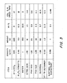
- Single cell testing of a fabricated matrix (Table 3 of FIG. 8 ) with the composition of Table 1 of FIG. 2 showed a good gas sealing efficiency, with undetectable reactant gas cross-over.
- a similar result was also obtained for the matrix prepared from the composition given in the Table 2 of FIG. 3 .
- thicknesses and mean pore sizes for the matrices of the invention are preferred, wider ranges are also usable.
- thicknesses in the range of 0.004" to 0.050" and mean pore sizes in the range of 0.06 to 0.40 ⁇ m diameter are also usable.
Landscapes
- Engineering & Computer Science (AREA)
- Chemical & Material Sciences (AREA)
- Manufacturing & Machinery (AREA)
- Ceramic Engineering (AREA)
- Organic Chemistry (AREA)
- Structural Engineering (AREA)
- Materials Engineering (AREA)
- Life Sciences & Earth Sciences (AREA)
- Sustainable Development (AREA)
- Sustainable Energy (AREA)
- Chemical Kinetics & Catalysis (AREA)
- Electrochemistry (AREA)
- General Chemical & Material Sciences (AREA)
- Fuel Cell (AREA)
Description
- This invention relates to carbonate fuel cells and, in particular, to matrices, and methods of making same, for use in such cells.
- Carbonate fuel cells offer a highly efficient and environmentally clean option for power generation. A key component in carbonate fuel cells is a porous (-40-50 vol.% porosity), thin (-0.5-1 mm) ceramic matrix filed with a carbonate electrolyte (for example, Li/K carbonate eutectic). The functions performed by the ceramic/electrolyte matrix in the carbonate fuel cell include: (1) electronic isolation of the anode and cathode compartments, (2) ionic conduction between the anode and cathode electrodes, and (3) separation of the anode and cathode compartment gases.
- The ceramic materials of the matrix provide the electronic isolation, while the carbonate electrolyte present within the pores of the ceramic matrix supports ionic conduction. The matrix pore sizes are required to be in the submicron range to achieve desired capillary force for retaining electrolyte and differential bubble pressure for preventing the anode and cathode compartment gases from crossing over. Large-size pores are avoided to adequately maintain the gas separation.
- During the last decade, gamma lithium aluminate (γ-LiAlO2) has been mainly used as the ceramic matrix support material in the carbonate fuel cell due to its chemical stability in the molten carbonate environment. Matrices made from ultra-fine γ-LiAlO2 powder (∼0.1-0.2µm) using a tape casting technique (see, e.g., German Patent
DE 3235240 ;U.S. Patent 4,353,958 ; andU.S. Patent 4,478,776 ) are able to provide a desired pore structure for retaining electrolyte and for realizing gas separation. The tape casting process involves dispersing the ceramic powder in a solvent, to which organic binders and a plasticizer are added to form a castable ceramic slurry. The slurry is subsequently casted into thin-sheet layers in a chambered tape casting machine. In this process, the solvents are evaporated by applying air and/or heating. - Organic solvents are primarily used as the tape casting vehicle in the ceramic matrix formation. However, the use of organic solvents involves a number of disadvantages. Firstly, working with organic solvents requires that appropriate protective measures be taken in order to avoid health hazards and the risk of explosion. Moreover, the organic solvents must be prevented from escaping into the atmosphere. As a result, the equipment requirements are severe. This drives up equipment costs. A second disadvantage of using organic solvents in the tape casting process is that the ceramic slurry tends to form a surface skin due to the very fast evaporation of the organic solvents. Such skinning significantly retards the as-cast matrix tape drying rate and may trap any unreleased air bubbles in the tape. Bubbles in the matrix tape result in undesirably large pores in the matrix. These large pores can result in detrimental reactant gas crossover, thereby lowering cell performance and shortening cell life.
- Despite the aforesaid disadvantages of organic solvents, they offer a more practical solvent than aqueous solvents because of the hydroscopic nature of the γ-LiAIO2. Water can hydrolyze the γ-LiAlO2 into lithium hydroxide and aluminum hydroxide. Although lithium aluminate may form again upon drying, the formed phase is the alpha or beta lithium aluminate phase, which phases have not been used to any great degree in matrix formation.
- Besides the phase transformation, the formation of widespread aggregates/agglomerates due to the hydrolysis of γ-LiAlO2 is also an obstacle to using an aqueous or water solvent in tape casting of γ-LiAlO2 matrices. These widespread aggregates caused by the hydrogen-bonding of the hydrolyzed particles are very difficult to deaggregate when using only the mechanical forces produced by standard milling. As a result, a slurry with excessively high viscosity is created so as to prevent practical ceramic processing.
- While few practical efforts have been made to use water as a solvent in the casting of γ-LiAlO2 matrices, a tape casting method which uses such an aqueous solvent is described in a recently issued
U.S. Patent No. 5,432,138 . In this method, a hydroxyl group polymer, such as polyvinyl alcohol (PVA), is used to bond the water molecules so as to prevent the hydrolysis of the γ-LiAlO2. Using this method, a flexible tape can be made from a slurry of gamma lithium powder directly stirred in a PVA/water mixture. - Although this method appears to prevent the hydrolysis of γ-LiAlO2 in the aqueous base processing, several concerns exist as to use of a matrix made with this method in carbonate fuel cell applications. A major concern is that such a matrix may not have a pore size distribution (which plays a key role in electrolyte storage and gas separation) adequate for carbonate fuel cells. It is believed that if the process of the '138 patent is followed, the high surface area γ-LiAlO2 tends to agglomerate easily so as to form uncontrolled lumps and clusters. These agglomerates or clusters will contain nearly random-sized pores, and the largest of these pores can seriously affect the sealing efficiency of the final matrix.
- Alpha lithium aluminate (α-LiAlO2) has been known to be more stable than γ-LiAlO2 in the molten carbonate environment, and efforts toward using this material in forming a carbonate fuel cell matrix have recently increased. Tape casting with an organic solvent is also the technique proposed for making α-LiAlO2 matrices with a desirable pore size distribution. However, tape casting of such a material using an aqueous or water solvent has not as yet been carried out.
- A difficulty in using a water solvent in the tape casting of α-LiAlO2 is the occurrence of hydration during the deflocculation step. Although the hydration product is eventually converted back into α-LiAlO2 upon drying, the tendency of high viscosity or gelation due to the hydrogen bond (H-bond) retards the deflocculation process. The extent of the gelation is strongly affected by the powder surface area, solid loading level, deflocculation time, and the dispersant used. The more the powder, i.e. , the higher the solids loading, the higher the viscosity. Also, the higher the total powder surface area, the easier the gelation. Experimental data indicates that if a high surface area α-LiAlO2 (≥20 m2/g) is stirred long enough (≥0.5 hour) in water, a gel or "cake" will form.
-
JP 63 294 668 - The invention as claimed in
claim 1 solves the problem of how to make a ceramic matrix having a desired pore size distribution and in which α-LiAlO2 and an aqueous solvent are used. - With the type of high energy milling stated in
claim 1, the deflocculation time is sufficiently limited, thereby retarding hydration effects. A dispersant, preferably, citric acid, is added to the aqueous solvent to retard agglomeration of the ceramic particles, thereby enhancing the deflocculation. - In further accord with the invention, the deflocculation process is followed by a slurry forming process in which the deflocculated mixture is added to and further mixed with a binder system comprised of a hydroxyl group polymer and a plasticizer. A preferable polymer is PVA and a preferable plasticizer is glycerol. The formed slurry is then degassed, tape cast and dried to complete the matrix formation.
- The above and other features and aspects of the present invention will become more apparent upon reading the following detailed description in conjunction with the accompanying drawings, in which:
-
FIG. 1 shows a flow diagram of a method for forming a ceramic matrix for carbonate electrolyte in accordance with the principles of the present invention; -
FIGS. 2 and3 show tables giving the constituent makeup of ceramic matrices made with the method ofFIG. 1 ; -
FIG. 4 shows sections of ceramic matrices formed by the method ofFIG. 1 ; -
FIG. 5 shows a graph of binder burnout versus temperature for ceramic matrices made with the method ofFIG. 1 ; -
FIGS. 6 and7 are graphs showing the porosity characteristics of ceramic matrices made with the method ofFIG. 1 ; and -
FIG. 8 shows the test data of a fuel cell utilizing a ceramic matrix made with the method ofFIG. 1 . -
FIG. 1 shows the steps of a method for making a ceramic matrix or tape with a desired pore size distribution using an aqueous solvent in accordance with the principles of the present invention. Preferably, the ceramic material used is α-LiAlO2 and, with the method of the invention, a stable suspension of the α-LiAlO2 in water is obtained. This suspension is then used in preparing an aqueous based tape casting slurry having a high solid loading (-60 vol.%) of the ceramic without the occurrence of gelation. - As shown in
FIG. 1 , the method of the invention is initiated with adeflocculation process 11. This process includes dispersing of an α-LiAlO2 powder in an aqueous solvent to which is also supplied a dispersant. The dispersed ceramic powder in the aqueous solvent is then subjected to a high-energy attrition milling. - The attrition milling allows complete deflocculation of the α-LiAlO2 in a very short time (-15 min to 0.5 hour), and thus reduces the extent of any α-LiAlO2 hydration. By high-energy attrition milling is meant milling using very small YTZ (yttrium toughened zirconia) grinding balls (-0.3 to 0.6 mm diameter) and a high milling speed (-1000 to 1500 RPM), or equivalent structure and/or parameters, with a high charge level of grinding or solid medium (-40 to 60 vol.%).
- The preferred dispersant used in the aqueous solvent is citric acid. The effect of citric acid on the α-LiAlO2 deflocculation is believed to be attributable to an electrical double layer repulsive force which separates particles far apart enough to prevent contact and agglomeration. This repulsive force is generated by creating a surface charge (positive) on the ceramic powder particles through the adsorption of citric acid. The extent of surface charging is determined by the amount of citric acid adsorbed on the particles.
- Once the high-energy attrition milling is completed, the deflocculation step is finished and the process moves to a slurry formation process or step 12. In this step, the deflocculated mixture is added to an aqueous binder system comprised of a hydroxyl group polymer and a plasticizer. Preferably, an aqueous binder system of polyvinyl alcohol (PVA)/Glycerol is used. The binder is formulated according to a ratio of PVA/Glycerol needed to avoid "depletion flocculation" or gelation which frequently occurs during the binder mixing in preparation of the ceramic slurry.
- The "depletion flocculation" or gelation during the binder mixing is also minimized by adjusting the amount of citric acid and the pH value of the binder. In the binder formulation, other additives such as a surfactant. (420 Surfactant, Air Products, Allentown, PA) and a defoamer (DF-75, Air Products, Allentown, PA) are also added. These additives reduce the slurry surface tension and the stability of bubbles for the purposes of defoaming and preventing tape separating during the casting.
- A PVA/Glycerol binder system is used because it has been found to contain very low levels of sulfur. Sulfur is highly restricted in the carbonate fuel cell because it not only enhances the corrosion of the components but also causes the poisoning of the anode and the reforming catalyst. Although acrylic binders have shown better polymer burn-out behavior than that of PVA, water based acrylic binders usually contain high levels of sulfur and cannot be used in the carbonate fuel cell.
- The slurry formation step is followed by a degassing
step 13 in which excess gases are removed from the slurry. In particular, entrapped air bubbles are allowed to escape or are removed by gentle mixing. This may be aided by providing a mild vacuum atmosphere. This step is then followed by a tape casting step 14 performed in a usual manner to result in a completed α-LiAlO2 matrix. - Examples of compositions of ceramic matrices formed using the method of the invention are depicted in
FIGS. 2 and3 . An illustrative example of the practice of the method of the invention to realize these matrices is described below. - The ceramic powder used in this example was α-LiAlO2 (Cyprus Foote Mineral Company, Kings Mountain, NC) having a surface area of 11.3 m2/g. X-ray diffraction analysis showed a negligible amount of gamma lithium aluminate (0.4 wt.%) in the as-received powder. An aqueous solution for the deflocculation step was prepared using citric acid (reagent grade, Aldrich, Milwaukee, WI) and distilled ("DI") water at a ratio of ∼1/20 to 1/15. The solution was stirred for 0.5 hour before adding the LiAlO2 ceramic powder.
- The amount of the ceramic powder was controlled so that the ratio of citric acid/ceramic powder remained at a ratio of 1/20 to 1/10. The deflocculation was carried out in a laboratory batch attritor which was equipped with a YTZ agitation shaft, a water-cooled alumina (99.8%) tank (1400 cc), and YTZ grinding balls (0.6 mm in diameter, 40 vol.% filled). The powder was gradually added into the aqueous solution and was attrition milled for 0.5 hour at 1000 RPM. After deflocculation, the aqueous mixture was separated from the grinding equipment and poured into a binder system to carry out the slurry formation step.
- The binder system was prepared from a polyvinyl alcohol binder (AIRVOL PVA, Air Product, Allentown, PA) and a Glycerol plasticizer (reagent grade, Aldrich, Milwaukee, WI). Three different grades of PVA were used for the binder preparation, including:
AIRVOL 203,AIRVOL 523 AND AIRVOL 502.AIRVOL 203 was mixed with eitherAIRVOL 523 or AIRVOL 502 in DI water at a temperature of 80°C. The weight ratio ofAIRVOL 203/AIRVOL 502 or 523 was adjusted between 1 to 2, and the amount of PVA dissolved in the water was about 25 to 35 wt.%. - After dissolving the PVA, glycerol was added and mixed to form a uniform binder system. The ratio of glycerol to PVA binder was about 0.5 to 1. A small amount (0.5 to 1.5 gram per 100 gram binder mixture) of defoamer (Surfynol DF-75, Air Product, Allentown, PA) was also added into the binder mixture for the defoaming purpose.
- Additionally, a surfactant (
Surfynol 420, Air Product, Allentown, PA) may also be added to the binder system to modify the binder surface tension and prevent separation of the slurry during the tape casting (in case the surface tension of the carrier is lower than the binder). Finally, the pH value of the binder was adjusted to -11.5 using 0.5% ammonium hydroxide before adding the deflocculated ceramic mixture. - The binder system and the deflocculated ceramic were stirred in a mixer at -30 to 50 RPM for 5 to 10 hours to form a homogeneous slurry. The amount of the binder was between 10 to 15 wt.% of the total solid loading, and the viscosity of the final slurry was between 2000 to 5000 CPS (Centipoises). During the mixing, about 15 to 20 wt.% reinforcement material, such as, large alumina (Al2O3) particles or platelets in the size ranging from 20 to 100 µm, was also added as crack attenuators.
- Tape casting of the slurry was conducted in a doctor blade caster using either silicon-coated polyester (PET, Maylar Grade D) or polymer coated paper (Ultracast patina PVC, S.D. Warren Co., Westbrook, ME) dependent on the surface tension of the slurry. A tape having a thickness of between 0.006" to 0.015" was cast at ∼10"/min and dried in the air for 12 hours. The dried tape was easily released from the carrier and showed homogeneous microstructure and thickness.
- Sections of a green matrix or tape cast from the slurry with the composition of Table 1 is shown in
FIG. 4 . The flexible tape showed desirable mechanical strength, lamination behavior as well as microstructure. The green tape was laminated at room-temperature using 2000 Psi pressure. -
FIG. 5 shows a thermogravimetric analysis (TGA) for the binder removal from fabricated matrices or tapes in either an oxidizing or an inert atmosphere. As can be seen, the binder removal starts in either atmosphere by thermolysis at approximately 220°C, and continuously occurs indicated by continuous loss of weight, with a relatively sharp transition between 400°C and 500°C. After binder removal, the fabricated matrices became brittle but retained structural integrity. -
FIGS. 6 and7 show a mercury porosimetry analysis of a fabricated matrix after the binder removal, indicating a small mean pore size of 0.2 µm diameter with a desired narrow, uniform pore size distribution of from about .02 to 0.8 µm diameter. Single cell testing of a fabricated matrix (Table 3 ofFIG. 8 ) with the composition of Table 1 ofFIG. 2 showed a good gas sealing efficiency, with undetectable reactant gas cross-over. A similar result was also obtained for the matrix prepared from the composition given in the Table 2 ofFIG. 3 . - It should be noted that, while the range of thicknesses and mean pore sizes for the matrices of the invention set forth above are preferred, wider ranges are also usable. In particular, thicknesses in the range of 0.004" to 0.050" and mean pore sizes in the range of 0.06 to 0.40 µm diameter are also usable.
- In all cases it is understood that the above-described arrangements are merely illustrative of the many possible specific embodiments which represent applications of the present invention. Numerous and varied other arrangements can be readily devised in accordance with the principles of the present invention without departing from the scope of the invention.
Claims (42)
- A method of forming a matrix for a carbonate fuel cell comprising:deflocculating a α-LiAlO2 ceramic material comprising:characterized in thatcombining said ceramic material with an aqueous solvent; andmilling said ceramic material in said aqueous solvent to deflocculate said ceramic material; andforming said deflocculated ceramic material in said mixture into a matrix;
said milling is carried out as high energy attrition milling such that substantially complete deflocculation is realized in a time period of about 15 min to 0.5 hours and said deflocculating further comprises adding a dispersant to said aqueous solvent. - A method in accordance with claim 1 wherein:said dispersant is citric acid.
- A method in accordance with claim 2 wherein:the ratio of ceramic material to dispersant is in the range of 1/20 to 1/15.
- A method in accordance with claim 1 wherein:the ratio of ceramic material to dispersant is in the range of 1/20 to 1/15.
- A method in accordance with claim 2 wherein:said high energy attrition milling is carried out over a period of time of between 15 and 30 minutes.
- A method in accordance with claim 5 wherein:said high energy attrition milling is carried out for a period of time of 30 minutes.
- A method in accordance with claim 5 wherein:said high energy attrition milling is carried out using YTZ grinding balls of 0.3 to 0.6 mm in diameter and a milling speed of 1000 to 1500 rpm, with the solid material being milled being present in the amount of 40 to 60 volume percent.
- A method in accordance with claim 7 wherein:the volume of ceramic material in said mixture is between 40 to 60 volume percent.
- A method in accordance with claim 7 wherein:said forming step comprises: combining said attrition milled mixture with a binder system to form a slurry.
- A method in accordance with claim 9 wherein:said binder system is an aqueous binder system of an hydroxyl group polymer and a plasticizer.
- A method in accordance with claim 10 wherein:said hydroxyl group polymer is polyvinyl alcohol and said plasticizer is glycerol.
- A method in accordance with claim 11 wherein:the amount of polyvinyl alcohol to water in said aqueous binder system is 25 to 35 weight percent; and the ratio of glycerol to polyvinyl alcohol is 0.5 to 1.
- A method in accordance with claim 12 wherein:said binder system further comprises a defoamer and a surfactant.
- A method in accordance with claim 13 wherein:said binder system further comprises an hydroxide to adjust the pH of the binder system.
- A method in accordance with claim 1 wherein:said high energy attrition milling is carried out over a period of time of between 15 and 30 minutes.
- A method in accordance with claim 15 wherein:said high energy attrition milling is carried out for a period of time of 30 minutes.
- A method in accordance with claim 15 wherein:said high energy attrition milling is carried out using YTZ grinding balls of 0.3 to 0.6 mm in diameter and a milling speed of 1000 to 1500 rpm, with the solid material being present in the amount of 40 to 60 volume percent.
- A method in accordance with claim 17 wherein:the volume of ceramic material in said mixture is between 40 to 60 volume percent.
- A method in accordance with claim 1 wherein:said forming step comprises combining said attrition milled mixture with a binder system to form a slurry.
- A method in accordance with claim 19 wherein:said binder system is an aqueous binder system of an hydroxyl group polymer and a plasticizer.
- A method in accordance with claim 20 wherein:said hydroxyl group polymer is polyvinyl alcohol and said plasticizer is glycerol.
- A method in accordance with claim 21 wherein:the amount of polyvinyl alcohol to water in said aqueous binder system was 25 to 35 weight percent; andthe ratio of glycerol to polyvinyl alcohol was 0.5 to 1.
- A method in accordance with claim 22 wherein:said binder system further comprises a defoamer and a surfactant.
- A method in accordance with claim 23 wherein:said binder system further comprises an hydroxide to adjust the pH of the binder system.
- A method in accordance with claim 1 wherein:said forming comprises:combining said attrition milled mixture of ceramic material and aqueous solvent with a binder system to form a slurry; andcasting said slurry to form said matrix.
- A method in accordance with claim 25 wherein:said matrix has a mean pore size of 0.06 to 0.4 µm diameter.
- A method in accordance with claim 26 wherein:said matrix has a pore size distribution of 0.02 to 0.8 µm diameter.
- A method in accordance with claim 27 wherein:said matrix has a mean pore size of 0.2 µm diameter.
- A method in accordance with claim 27 wherein:said matrix has a thickness in a range of 0.1 to 1.27 mm (0.004 to 0.050 inches).
- A method in accordance with claim 29 wherein:said matrix has a thickness in a range of 0.15 to 0.38 mm (0.006 to 0.015 inches).
- A method in accordance with claim 25 wherein:said deflocculating further comprises combining a dispersant with said aqueous solvent; andsaid binder system is an aqueous binder system of an hydroxyl group polymer and a plasticizer.
- A method in accordance with claim 31 wherein:said high energy attrition milling is carried out using YTZ grinding balls of 0.3 to 0.6 mm diameter and a milling speed of 1000 to 1500 rpm, with the solid material being milled being present in an amount of 40 to 60 volume percent; andsaid hydroxyl group polymer is polyvinyl alcohol and said plasticizer is glycerol.
- A method in accordance with claim 25 wherein:said combining step includes mixing said binder and attrition milled mixture.
- A method in accordance with claim 33 wherein:said mixing of said binder and attrition milled mixture is carried out in a mixer running at a speed of 30 to 50 rpm for a period of 5 to 10 hours.
- A method in accordance with claim 33 wherein:said slurry has a viscosity of 2000 to 5000 CPS.
- A method in accordance with claim 33 wherein:said binder is in a range of 10 to 15 wt.% of the solid loading of said slurry.
- A method in accordance with claim 25 further comprising:combining crack attenuator material with said attrition milled mixture and said binder system.
- A method in accordance with claim 37 wherein:said crack attenuator material is 15 to 20 wt.% of the solid content of said slurry.
- A method in accordance with claim 37 wherein:said crack attenuator material is in the form of one or more of particles and platelets.
- A method in accordance with claim 39 wherein:said one or more of said particles and platelets are of a size of 20 to 100 µm.
- A method in accordance with claim 40 wherein:said crack attenuator material comprises alumina.
- A method in accordance with claim 37 wherein:said crack attenuator material comprises alumina.
Applications Claiming Priority (3)
| Application Number | Priority Date | Filing Date | Title |
|---|---|---|---|
| US135811 | 1993-10-12 | ||
| US09/135,811 US5997794A (en) | 1998-08-18 | 1998-08-18 | Method of making matrix for carbonate fuel cells |
| PCT/US1999/014421 WO2000010939A1 (en) | 1998-08-18 | 1999-06-25 | A matrix for carbonate fuel cells and a method of making same |
Publications (3)
| Publication Number | Publication Date |
|---|---|
| EP1109759A1 EP1109759A1 (en) | 2001-06-27 |
| EP1109759A4 EP1109759A4 (en) | 2004-05-12 |
| EP1109759B1 true EP1109759B1 (en) | 2009-08-05 |
Family
ID=22469799
Family Applications (1)
| Application Number | Title | Priority Date | Filing Date |
|---|---|---|---|
| EP99930724A Expired - Lifetime EP1109759B1 (en) | 1998-08-18 | 1999-06-25 | A matrix for carbonate fuel cells and a method of making same |
Country Status (5)
| Country | Link |
|---|---|
| US (1) | US5997794A (en) |
| EP (1) | EP1109759B1 (en) |
| CN (1) | CN1296316C (en) |
| DE (1) | DE69941218D1 (en) |
| WO (1) | WO2000010939A1 (en) |
Families Citing this family (7)
| Publication number | Priority date | Publication date | Assignee | Title |
|---|---|---|---|---|
| JP2001114569A (en) * | 1999-10-20 | 2001-04-24 | Murata Mfg Co Ltd | Ceramic slurry composition, ceramic green sheet and production of multilayer ceramic electronic part |
| JP2004517441A (en) * | 2000-11-15 | 2004-06-10 | エム・テー・ウー・シーエフシー・ソルーションズ・ゲゼルシャフト・ミト・ベシュレンクテル・ハフツング | In particular, an electrolyte matrix for a molten carbonate fuel cell and a method for producing the electrolyte matrix |
| US20080032183A1 (en) * | 2006-08-07 | 2008-02-07 | Gengfu Xu | Coated support material for use in fabricating a fuel cell matrix and method of forming same using alkaline precursors |
| WO2009020835A2 (en) | 2007-08-03 | 2009-02-12 | Errcive, Inc. | Porous bodies and methods |
| US8277743B1 (en) | 2009-04-08 | 2012-10-02 | Errcive, Inc. | Substrate fabrication |
| US8359829B1 (en) | 2009-06-25 | 2013-01-29 | Ramberg Charles E | Powertrain controls |
| US9833932B1 (en) | 2010-06-30 | 2017-12-05 | Charles E. Ramberg | Layered structures |
Family Cites Families (14)
| Publication number | Priority date | Publication date | Assignee | Title |
|---|---|---|---|---|
| US539943A (en) * | 1895-05-28 | Armature-winding and method of making same | ||
| US2486410A (en) * | 1944-09-15 | 1949-11-01 | Glenn N Howatt | Continuous process for forming high dielectric ceramic plates |
| US3238079A (en) * | 1962-11-13 | 1966-03-01 | Winalee G Mitchell | Method for fabrication of plastic footwear |
| US3238049A (en) * | 1963-01-23 | 1966-03-01 | Gen Motors Corp | Dry grinding of ceramics |
| JPS5817143B2 (en) * | 1979-02-22 | 1983-04-05 | 鳴海製陶株式会社 | Ceramic tape manufacturing method |
| US4478776A (en) * | 1981-09-30 | 1984-10-23 | Maricle Donald L | Method of making molten carbonate fuel cell ceramic matrix tape |
| JPS62160663A (en) * | 1986-01-04 | 1987-07-16 | Kobe Steel Ltd | Production of porous aluminate lithium sintered body |
| JPS63294668A (en) * | 1987-05-27 | 1988-12-01 | Toppan Printing Co Ltd | Matrix for fused carbonate fuel cell |
| US5399443A (en) * | 1992-02-12 | 1995-03-21 | Electric Power Research Institute, Inc. | Fuel cells |
| DE4238292C1 (en) * | 1992-11-13 | 1994-03-17 | Deutsche Aerospace | Process for producing a lithium aluminate matrix layer for a molten carbonate fuel cell |
| US5580673A (en) * | 1993-01-19 | 1996-12-03 | Energy Research Corporation | Carbonate fuel cell matrix |
| JP3154313B2 (en) * | 1993-07-23 | 2001-04-09 | 住友電気工業株式会社 | Method and apparatus for manufacturing ceramic sintered body |
| JPH0997620A (en) * | 1995-10-03 | 1997-04-08 | Toshiba Corp | Method for producing molten carbonate fuel cell and holding material for electrolyte plate of molten carbonate fuel cell |
| US5869203A (en) * | 1996-12-13 | 1999-02-09 | Energy Research Corporation | Electrolyte matrix for molten carbonate fuel cells |
-
1998
- 1998-08-18 US US09/135,811 patent/US5997794A/en not_active Expired - Lifetime
-
1999
- 1999-06-25 EP EP99930724A patent/EP1109759B1/en not_active Expired - Lifetime
- 1999-06-25 DE DE69941218T patent/DE69941218D1/en not_active Expired - Lifetime
- 1999-06-25 WO PCT/US1999/014421 patent/WO2000010939A1/en not_active Ceased
- 1999-06-25 CN CNB998097721A patent/CN1296316C/en not_active Expired - Fee Related
Also Published As
| Publication number | Publication date |
|---|---|
| EP1109759A1 (en) | 2001-06-27 |
| EP1109759A4 (en) | 2004-05-12 |
| CN1312781A (en) | 2001-09-12 |
| CN1296316C (en) | 2007-01-24 |
| DE69941218D1 (en) | 2009-09-17 |
| US5997794A (en) | 1999-12-07 |
| WO2000010939A1 (en) | 2000-03-02 |
Similar Documents
| Publication | Publication Date | Title |
|---|---|---|
| US9997270B2 (en) | Lithium ion conductive substance, lithium ion conductive solid electrolyte using the lithium ion conductive substance, protective layer for an electrode of a lithium ion battery, and method for manufacturing the lithium ion conductive substance | |
| JP2025542592A (en) | Solid electrolyte membrane, its manufacturing method and uses, and solid-state battery | |
| CN100379076C (en) | Electrolyte matrix for molten carbonate fuel cells | |
| US5453101A (en) | Process for producing composite active electrolyte-matrix and laminated component tapes for molten carbonate fuel cells | |
| US5997794A (en) | Method of making matrix for carbonate fuel cells | |
| Corbin et al. | Development of solid oxide fuel cell anodes using metal‐coated pore‐forming agents | |
| KR20100047703A (en) | An electrolyte-filled and reinforced matrix for molten carbonate fuel cell and method for producing the same | |
| JP6291073B2 (en) | Fuel cell matrix composition and method for producing the same | |
| CN115466116A (en) | Porous lithium lanthanum zirconium oxygen solid electrolyte sheet and preparation method and application thereof | |
| EP1883986B1 (en) | Electrolyte matrix for molten carbonate fuel cells with improved pore size and method of manufacturing same | |
| JP3434127B2 (en) | Fuel cell sealing material and method of manufacturing the same | |
| Cho et al. | Fabrication and Characterization of γ‐LiAlO2 Matrices Using an Aqueous Tape‐Casting Process | |
| KR100350364B1 (en) | Ceramic Fiber Reinforced Matrix for Molten Carbonate Fuel Cell and a Process for Production Thereof | |
| EP2054962A2 (en) | Coated support material for use in fabricating a fuel cell matrix and method of forming same using alkaline precursors | |
| CN119852641B (en) | Lithium dendrite growth resistant composite diaphragm, preparation method thereof and lithium ion battery | |
| CN120149745B (en) | High-temperature-isolation corrosion-resistant lithium battery ceramic fiber paper and preparation method thereof | |
| RU2834013C1 (en) | Method of making cathode plate for fuel cell with molten carbonate electrolyte | |
| KR100779741B1 (en) | Reinforcing Matrix for Molten Carbonate Fuel Cell with Sintering Aid | |
| WO1993024964A1 (en) | High porosity aluminum nitride separator | |
| KR100354819B1 (en) | Method for manufacturing γ-LiAlO2 matrix for Molten Carbonate Fuel Cell | |
| JPH06290799A (en) | Method for producing electrolyte plate of molten carbonate fuel cell | |
| JP2000511683A (en) | Method for producing a plate-shaped member or combination of members | |
| KR20000043716A (en) | Method for manufacturing a fuel electrode | |
| Batra et al. | Fabrication of porous components for molten carbonate fuel cell | |
| JPH0626130B2 (en) | Method for manufacturing electrolyte plate for molten carbonate fuel cell |
Legal Events
| Date | Code | Title | Description |
|---|---|---|---|
| PUAI | Public reference made under article 153(3) epc to a published international application that has entered the european phase |
Free format text: ORIGINAL CODE: 0009012 |
|
| 17P | Request for examination filed |
Effective date: 20010207 |
|
| AK | Designated contracting states |
Kind code of ref document: A1 Designated state(s): DE FR GB IT |
|
| RIN1 | Information on inventor provided before grant (corrected) |
Inventor name: YUH, CHAO-YI Inventor name: DOYON, JOEL, D. Inventor name: HUANG, CHAO, M., XIAMEN THREE CIRCLES ERC BATTERY |
|
| A4 | Supplementary search report drawn up and despatched |
Effective date: 20040330 |
|
| RIC1 | Information provided on ipc code assigned before grant |
Ipc: 7H 01M 8/02 B Ipc: 7C 04B 35/634 B Ipc: 7C 04B 35/44 A |
|
| 17Q | First examination report despatched |
Effective date: 20050125 |
|
| 17Q | First examination report despatched |
Effective date: 20050125 |
|
| GRAP | Despatch of communication of intention to grant a patent |
Free format text: ORIGINAL CODE: EPIDOSNIGR1 |
|
| GRAS | Grant fee paid |
Free format text: ORIGINAL CODE: EPIDOSNIGR3 |
|
| GRAA | (expected) grant |
Free format text: ORIGINAL CODE: 0009210 |
|
| AK | Designated contracting states |
Kind code of ref document: B1 Designated state(s): DE FR GB IT |
|
| REG | Reference to a national code |
Ref country code: GB Ref legal event code: FG4D |
|
| REF | Corresponds to: |
Ref document number: 69941218 Country of ref document: DE Date of ref document: 20090917 Kind code of ref document: P |
|
| PLBE | No opposition filed within time limit |
Free format text: ORIGINAL CODE: 0009261 |
|
| STAA | Information on the status of an ep patent application or granted ep patent |
Free format text: STATUS: NO OPPOSITION FILED WITHIN TIME LIMIT |
|
| 26N | No opposition filed |
Effective date: 20100507 |
|
| GBPC | Gb: european patent ceased through non-payment of renewal fee |
Effective date: 20100625 |
|
| REG | Reference to a national code |
Ref country code: FR Ref legal event code: ST Effective date: 20110228 |
|
| PG25 | Lapsed in a contracting state [announced via postgrant information from national office to epo] |
Ref country code: IT Free format text: LAPSE BECAUSE OF NON-PAYMENT OF DUE FEES Effective date: 20100625 |
|
| PG25 | Lapsed in a contracting state [announced via postgrant information from national office to epo] |
Ref country code: FR Free format text: LAPSE BECAUSE OF NON-PAYMENT OF DUE FEES Effective date: 20100630 |
|
| PG25 | Lapsed in a contracting state [announced via postgrant information from national office to epo] |
Ref country code: GB Free format text: LAPSE BECAUSE OF NON-PAYMENT OF DUE FEES Effective date: 20100625 |
|
| PGFP | Annual fee paid to national office [announced via postgrant information from national office to epo] |
Ref country code: DE Payment date: 20120627 Year of fee payment: 14 |
|
| REG | Reference to a national code |
Ref country code: DE Ref legal event code: R119 Ref document number: 69941218 Country of ref document: DE Effective date: 20140101 |
|
| PG25 | Lapsed in a contracting state [announced via postgrant information from national office to epo] |
Ref country code: DE Free format text: LAPSE BECAUSE OF NON-PAYMENT OF DUE FEES Effective date: 20140101 |