EP1109646B1 - Method and apparatus for lapping or testing gears - Google Patents
Method and apparatus for lapping or testing gears Download PDFInfo
- Publication number
- EP1109646B1 EP1109646B1 EP99945447A EP99945447A EP1109646B1 EP 1109646 B1 EP1109646 B1 EP 1109646B1 EP 99945447 A EP99945447 A EP 99945447A EP 99945447 A EP99945447 A EP 99945447A EP 1109646 B1 EP1109646 B1 EP 1109646B1
- Authority
- EP
- European Patent Office
- Prior art keywords
- machine
- lapping
- spindle
- members
- axis
- Prior art date
- Legal status (The legal status is an assumption and is not a legal conclusion. Google has not performed a legal analysis and makes no representation as to the accuracy of the status listed.)
- Expired - Lifetime
Links
- 238000000034 method Methods 0.000 title claims description 30
- 238000012360 testing method Methods 0.000 title claims description 12
- 150000001875 compounds Chemical class 0.000 claims description 22
- 230000008569 process Effects 0.000 claims description 13
- 230000007704 transition Effects 0.000 claims description 8
- 230000013011 mating Effects 0.000 claims description 6
- 230000007423 decrease Effects 0.000 claims 1
- 230000033001 locomotion Effects 0.000 description 22
- 230000008859 change Effects 0.000 description 10
- 230000000694 effects Effects 0.000 description 10
- 238000013016 damping Methods 0.000 description 9
- 239000003795 chemical substances by application Substances 0.000 description 5
- 230000001965 increasing effect Effects 0.000 description 4
- 230000001133 acceleration Effects 0.000 description 3
- 238000005520 cutting process Methods 0.000 description 3
- 238000011161 development Methods 0.000 description 3
- 238000003754 machining Methods 0.000 description 3
- 238000004519 manufacturing process Methods 0.000 description 3
- 239000002184 metal Substances 0.000 description 3
- 229910052751 metal Inorganic materials 0.000 description 3
- 230000009290 primary effect Effects 0.000 description 3
- 230000008901 benefit Effects 0.000 description 2
- 230000002708 enhancing effect Effects 0.000 description 2
- 238000011156 evaluation Methods 0.000 description 2
- 239000007788 liquid Substances 0.000 description 2
- 238000009825 accumulation Methods 0.000 description 1
- 230000002411 adverse Effects 0.000 description 1
- 230000009286 beneficial effect Effects 0.000 description 1
- 230000015572 biosynthetic process Effects 0.000 description 1
- 238000010276 construction Methods 0.000 description 1
- 230000003247 decreasing effect Effects 0.000 description 1
- 238000013461 design Methods 0.000 description 1
- 230000008030 elimination Effects 0.000 description 1
- 238000003379 elimination reaction Methods 0.000 description 1
- 238000007730 finishing process Methods 0.000 description 1
- 239000012530 fluid Substances 0.000 description 1
- 238000010438 heat treatment Methods 0.000 description 1
- 238000005259 measurement Methods 0.000 description 1
- 239000000203 mixture Substances 0.000 description 1
- 238000012544 monitoring process Methods 0.000 description 1
- 239000003921 oil Substances 0.000 description 1
- 230000009467 reduction Effects 0.000 description 1
- 238000005096 rolling process Methods 0.000 description 1
- HBMJWWWQQXIZIP-UHFFFAOYSA-N silicon carbide Chemical compound [Si+]#[C-] HBMJWWWQQXIZIP-UHFFFAOYSA-N 0.000 description 1
- 229910010271 silicon carbide Inorganic materials 0.000 description 1
- 238000001228 spectrum Methods 0.000 description 1
- 238000012956 testing procedure Methods 0.000 description 1
- 230000009466 transformation Effects 0.000 description 1
- XLYOFNOQVPJJNP-UHFFFAOYSA-N water Substances O XLYOFNOQVPJJNP-UHFFFAOYSA-N 0.000 description 1
Images




Classifications
-
- G—PHYSICS
- G01—MEASURING; TESTING
- G01M—TESTING STATIC OR DYNAMIC BALANCE OF MACHINES OR STRUCTURES; TESTING OF STRUCTURES OR APPARATUS, NOT OTHERWISE PROVIDED FOR
- G01M13/00—Testing of machine parts
- G01M13/02—Gearings; Transmission mechanisms
-
- G—PHYSICS
- G01—MEASURING; TESTING
- G01M—TESTING STATIC OR DYNAMIC BALANCE OF MACHINES OR STRUCTURES; TESTING OF STRUCTURES OR APPARATUS, NOT OTHERWISE PROVIDED FOR
- G01M13/00—Testing of machine parts
- G01M13/02—Gearings; Transmission mechanisms
- G01M13/021—Gearings
-
- B—PERFORMING OPERATIONS; TRANSPORTING
- B23—MACHINE TOOLS; METAL-WORKING NOT OTHERWISE PROVIDED FOR
- B23F—MAKING GEARS OR TOOTHED RACKS
- B23F19/00—Finishing gear teeth by other tools than those used for manufacturing gear teeth
- B23F19/02—Lapping gear teeth
- B23F19/025—Lapping bevel gears by making use of a correspondingly shaped counterpart
Definitions
- the present invention is directed to a method and apparatus for testing or finishing gears. Specifically, the present invention discloses a method and apparatus for lapping bevel and hypoid gears.
- Lapping is a well established process for finishing the tooth surfaces of bevel gears. It is a process that provides an economical alternative to other hard finishing processes for bevel gears and it has been used in all areas except for some aircraft applications.
- a pinion and ring gear are mounted, via appropriate workholding equipment, to respective spindles in a lapping machine that has the same basic design as a testing machine.
- the pinion is the driving member and the ring gear is braked.
- the gears are rolled in mesh and lapping compound, which can be a mixture of oil (or water) and silicon carbide or similar abrasive, is poured into the meshing zone. Examples of lapping and/or testing machines can be found in U.S. Patents Nos. 3,099,901 to Hunkeler; 3,142,940 to Rebeski; 3,717,958 to Ellwanger et al.; or, 5,609,058 to Gnadt et al.
- the first freedom being relative movement in the direction of the ring rear axis which shall be referred to as direction G or the G axis
- the second freedom being relative movement in direction of the pinion axis which shall be referred to as direction H or the H axis
- the third degree of freedom being distance between the ring gear and pinion axes which shall be referred to as direction V or the V axis.
- the direction V is also known as the "hypoid offset.”
- the V, H and G movements each have an effect on both the lengthwise and depthwise position of the localized tooth contact pattern, the primary effect of the V-axis movement being on the relative lengthwise position of the contact pattern, the primary effect of H-axis movement being on the relative depthwise position of the contact pattern, and the primary effect of G-axis movement being on the backlash.
- lapping machines usually has been similar to the construction principle as bevel gear cutting and grinding machines except that in most lapping machines, the shaft angle is permanently set to 90°.
- lapping machines have one less degree of freedom than cutting and/or grinding machines.
- US Patent No. 5,609,058 relates to a method of determining gear set backlash and describes a lapping machine capable of relative rotational and traditional movement of the members of the gear set.
- It is a further object to provide a high speed lapping process including a method to introduce lapping compound during the high speed lapping as well as monitoring vibration of a gearset during lapping as a means to signal optimal conditions of the lapped gearset.
- a first aspect of the present invention is directed to a machine for lapping or testing gears.
- the machine comprises a single machine column or base having a first side oriented perpendicular to a second side with the first side having a first workpiece spindle rotatable about a first axis and the second spindle having a second workpiece spindle rotatable about a second axis.
- the first workpiece spindle is movably secured to the first side and the second workpiece spindle is movably secured to the second side.
- the first and second workpiece spindles are movable with respect to one another along one or more of mutually perpendicular directions G, H and V. At least one, and preferably both, of the spindles are direct drive spindles.
- the inventive machine is such that at any relative position of the spindles and their associated gear members along the G, H and V directions, the crossing points of their respective axes remains the same.
- the machine of the present invention further indudes means to introduce lapping compound at the toe end of one of the members rotating in mesh at a location before the point of mesh.
- a second aspect of the present invention provides a method of lapping mating members of a gear set according to claim 17.
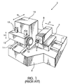
- Figure 1 shows a lapping machine 2 of the prior art wherein the machine comprises a frame 4 on which is located a pinion column 6 movable in a direction G on the frame 4 via ways 7. Located on pinion column 6 is a spindle 8 for rotating a pinion member 9 about its axis. Also located on frame 4 is gear column 10 movable in a direction H via ways 11 positioned on the frame 4. Gear spindle 12 is mounted to gear column 10 and is movable along ways 13 in a direction V. Gear 14 is rotatable about its axis on gear spindle 12.
- Directions G, H and V are mutually perpendicular with respect to one another.
- the gear spindle 12 is located well above the frame and thus, spindle 12 lies at a distance from the machine stiffness provided by the frame 4. Furthermore, there are several machine elements between the pinion spindle 8 and the ring gear spindle 12. Both of these conditions result in an accumulation of compliance. While some rotational compliance may be desirable, the prior art lapping machine introduces compliance in the three linear directions G, H and V which lowers the positioning accuracy of the pinion and ring gear in space.
- the spindle crossing point of the spindle axes changes depending on such factors as different size jobs, different ratios and different work holding equipment.
- the spindle crossing point is a point defined by the crossing of the spindle axes and is independent of any distance (V direction) between them.
- Figure 2 illustrates the crossing point of the machine of Figure 1 by showing the spindles of Figure 1 in a top view which effectively disregards the V direction.
- the gear pair members (9, 14) are engaged as shown, the gear spindle axis, A G , and the pinion spindle axis, A P , cross as point P 1 .
- the crossing point must change. If the pinion member 9 to be lapped is of a larger size, the pinion spindle axis A P may need to be moved by some amount ⁇ G from its initial position to account for the increased gear member diameter. In doing so, the spindle axes crossing point moves to P 2 .
- Figure 3 illustrates the inventive machine without doors and exterior sheet metal.
- the machine 20 comprises a single column 22 that may also be thought of as the machine frame.
- Column 22 comprises at least three sides, preferably four sides, with at least two of the sides, first side 24 and second side 26, being perpendicular to one another.
- Each of the first and second sides comprises a width and a height (as viewed in Figure 3).
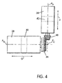
- First side 24 includes first workpiece spindle 28 which is rotatable about axis A G ( Figure 4) and is preferably driven by a direct drive motor 30, preferably liquid-cooled, mounted between front and rear spindle bearings (not shown).
- Spindle 28 is movable along the width of first side 24 in direction G on ways 32 attached directly to column 22. Movement of spindle 28 in direction G is provided by motor 34 through a direct-coupled ballscrew (not shown).
- a bevel ring gear member 36 is releasably mounted to spindle 28 by suitable workholding equipment as is known in the art.
- Second side 26 includes second workpiece spindle 38 which is rotatable about axis A P ( Figure 4) and is preferably driven by a direct drive motor 40, preferably liquid-cooled, mounted between front and rear spindle bearings (not shown) with motor 40 capable of attaining a pinion rotation of about 4000 RPM (the RPM of motor 30 would be: pinion RPM/ratio of the gearset).
- a direct drive motor 40 preferably liquid-cooled, mounted between front and rear spindle bearings (not shown) with motor 40 capable of attaining a pinion rotation of about 4000 RPM (the RPM of motor 30 would be: pinion RPM/ratio of the gearset).
- Spindle 38 is movable along the width of second side 26 in direction H on ways 42 attached to slide 44. Movement of spindle 38 in direction H is provided by motor 46 through a direct-coupled ballscrew. Preferably, a pinion member 48 is releasably mounted to spindle 38 by suitable workholding equipment as is known in the art. Workpiece spindle 38 is also movable along the height of second side 26 in direction V since slide 44 is movable in the V direction via ways 50 with movement being provided by motor 52 through a direct-coupled ballscrew.
- Directions G, H and V are mutually perpendicular with respect to one another. For practical purposes as well as for purposes of illustration, in Figure 1, the V direction is vertical.
- first work spindle 28 in direction G, second work spindle 38 in direction H, slide 44 in direction V, as well as first spindle rotation and second spindle rotation is imparted by the separate drive motors 34, 46, 52, 30 and 40 respectively.
- the above-named components are capable of independent movement with respect to one another or may move simultaneously with one another.
- Each of the respective motors is associated a feedback device such as a linear or rotary encoder (not shown) as part of a CNC system which governs the operation of the drive motors in accordance with instructions input to a computer controller such as the Fanuc model 16i.
- a tank for holding lapping compound is preferably placed under second spindle 38 adjacent to second side 26 as outlined by 54. In this manner, the tank can remain within the exterior sheet metal housing thus keeping the machine footprint size at a minimum. Also, a cutout area 56 of the column 22 may be included at an area of the column remote from the spindles for placement of any necessary electrical transformers. With this arrangement, such electrical components can also stay within the exterior sheet metal enclosure and yet be spaced far enough from the spindles such that heat radiating from the electrical components will not adversely influence the accuracy of the spindles or other tolerance sensitive elements.
- First work spindle 28 is attached to column 22 while second work spindle 38 has only slide 44 between it and column 22.
- uncontrolled compliance is significantly reduced and any desired compliance can be controlled by machine motions in the G, H and/or V directions.
- FIGS 7(a)-7(d) dynamically illustrate the spindle of a prior art lapping machine and the spindle of the lapping machine of the present invention.
- a motor 70 with an inertia I 1 is connected to a spindle 72 via a drive belt 74 having a rotational spring rate ⁇ 1 and a rotational damping factor ⁇ 1 .
- Spindle 72 has inertia I 2 and workpiece 76 has inertia I 3 . Since spindle 72 and workpiece 76 are rigidly connected through workholding equipment, only one rotational spring rate ⁇ 2 and one rotational damping factor ⁇ 2 apply to these components.
- the machine of the present invention accomplishes movement in the G and H directions while keeping the crossing point P C of the spindle axes in the same location.
- movement of first work spindle 28 in the G direction is movement, ⁇ G, along axis A G and hence, does not change the position of axis A G .
- movement of second work spindle 38 in the H direction is movement, ⁇ H, along axis A P which does not change the position of axis A P .
- the location of crossing point P C remains unaffected.
- the crossing point P C of the present invention will not change which greatly enhances the dynamic behavior of the machine.
- Another advantage brought about by the stationary crossing point P C is that the machining chamber is smaller thereby making it easier for a machine operator or automated loading/unloading equipment to gain access to the workpieces. Also in the present invention, the machining chamber is located at the corner of the machine, further enhancing the ease of accessibility.
- Lapping with the present invention can take place at very high speeds, for example, pinion rotation at about 2500 - 4000 RPM, which is generally about three times faster than conventional lapping. If a gearset having a ratio of 3:1 is lapped at a pinion speed of 3500 RPM, the ring gear member of the set will rotate at about 1170 RPM.
- a ring gear 60 has some similarity with a turbine blade 62.
- the twist on a turbine blade moves a gas or liquid axially by rotation of the turbine wheel.
- the cross section between two blades is smaller at the inner end and bigger at the outer diameter.
- Liquid, presented to the inner diameter of a turbine pump starts to spin around with the blades.
- the centrifugal force moves it to the outer diameter where the cross section between the blades is bigger. This movement introduces suction towards the inner diameter that helps the centrifugal force to pump the fluid from the inner to the outer diameter.
- the inventors have discovered that the above principle also has application in lapping procedures where high speeds are utilized as described above.
- the lapping compound is sprayed tangentially onto the toe (inner) end of the ring gear 48 in the direction of rotation R as is shown by nozzle 64 in Figure 6.
- the speed of the lapping compound exiting nozzle 64 should be about the same as the circumferential speed of the inner ring gear diameter.
- the lapping compound has to be sprayed onto the ring gear 48 before meshing occurs with pinion 36 such that the lapping compound is pumped into the tooth slots before meshing contact starts.
- a nozzle 66 is necessarily located on the other side of pinion 36.
- the present inventive machine may further include seismic measurement of structure born noise during the lapping process.
- a three dimensional accelerometer may be connected to either spindle but preferably the ring gear spindle. Real-time vibrations or fast Fourier transformation results are available to monitor the lapping cycles.
- the accelerometer may remain active to monitor some or all gear sets.
- the characteristic vibration scheme of a good gearset is stored in an evaluation computer. At this point, tolerances can be applied to provide a spectrum of permissible values where production gearsets are accepted as non-rejected, good gearsets.
- This closest point is defined as the time when vibration amplitudes turn from decreasing to increasing.
- the measured closest point amplitude is compared to the acceptable tolerance band established during development of the gearset and the gearset is accepted or rejected.
- the lapping process is terminated individually after the vibration amplitude turning point is reached. Since pinions and ring gears coming from heat treatment have some amount of individual distortions, the best lapping result for a particular gear pair is not expected to be the same for all gearsets in the production batch. The individual termination of the lapping process assures a higher and more consistent quality of the finished gearsets as well as the shortest cycle times.
- the present invention also contemplates changing speed and/or braking torque from point to point on a tooth surface during the lapping process.
- Figure 8 shows a tooth 80 on which three points are located, center point 82, toe-end point 84 and heel-end point 86.
- contact would begin at center point 82, shift to toe point 84, move back to center 82 and on to heel point 86 before returning to center 82.
- the present invention provides for the transition in speeds and torques to take place linearly during the move from point 82 to point 84 whereas in the prior art, the described change would be made abruptly at or prior to point 84.
- Such abrupt changes result in a stepped surface being formed on the tooth surface which leads to increased noise in the gearset.
- the inventive method provides for a smooth transition thus avoiding the formation of a stepped tooth surface. It is to be understood that the linear transition between points can be between any points on the tooth surface, for example between toe point 84 and heel point 86 in Figure 8.
- the present method also applies to tooth surfaces having any number of predetermined tooth surface points, such as six or nine.
- the transition between multiple points on a tooth surface may be different between each set of points.
- the desired speed and torque values at point 84 may be 2000 RPM and 2 Nm, respectively, while those at center point 82 may be 3000 RPM and 5 Nm.
- the desired lapping values may be 3800 RPM and 6 Nm.
- the transition rate of change between points 84 and 82 is different that the rate of change between points 82 and 86.
- the inventive machine may also function as a testing machine for bevel and hypoid gears.
- a testing machine the tooth surfaces of one member of the pair, usually the gear member, are coated with a marking compound and then run the pair together under a light load. Marking compound will be removed from areas of the gear tooth surface which come into contact with tooth surfaces of the mating pinion member resulting in a contact pattern or "footprint" being revealed on the tooth surfaces of the gear. The position and length of the contact pattern can then be evaluated.
- the direct drive motors of the present invention provide for testing procedures to be carried out under high speeds while the single column concept offers high strength and accuracy.
- the fixed crossing point offers extremely good acoustic conditions for noise vibration testing since machine acoustics will remain substantially constant even with movement in the G, H and V directions.
- machine acoustics change as the crossing point position changes thus making noise evaluation difficult.
Landscapes
- Physics & Mathematics (AREA)
- General Physics & Mathematics (AREA)
- Engineering & Computer Science (AREA)
- Mechanical Engineering (AREA)
- Finish Polishing, Edge Sharpening, And Grinding By Specific Grinding Devices (AREA)
- Gear Processing (AREA)
- Gears, Cams (AREA)
- Crushing And Grinding (AREA)
Description
Claims (22)
- A machine for lapping or testing gears, said machine comprising:said first side having a first workpiece spindle (28) rotatable about a first axis (AG) said first workpiece spindle being movably secured to said first side;a single machine column (22) having a first side (24) oriented perpendicular to a second side (26);
said second side having a second workpiece spindle (38) rotatable about a second axis (Ap) said second workpiece spindle being movably secured to said second side;
said first and second workpiece spindles being movable with respect to one another along one or more of mutually perpendicular directions G, H and V. - The machine of claim 1 wherein said first side has a width and a height with said first workpiece spindle being movable in direction G along said width.
- The machine of claim 2 wherein said first spindle is movable in said width direction G via ways secured to the first side of said column.
- The machine of claim 1 wherein said second side had a width and a height with said second workpiece spindle being movable in direction H along said width and in direction V along said height.
- The machine of claim 4 wherein said second spindle is movable in said width direction H via ways secured to a slide, said slide being movable in said height direction V via ways secured to the second side of said column.
- The machine of claim 1 wherein at least one of said first and second spindles are direct drive spindles.
- The machine of claim 1 wherein said first and second axes cross to define a crossing point (PC), said crossing point remaining the same regardless of the relative position of said first and second spindles along one or more of said directions G, H and V.
- The machine of claim 1 wherein said first spindle includes a bevel ring gear (36) mounted thereon for rotation about said first axis and wherein said second spindle includes a mating pinion (48) mounted thereon for rotation about said second axis.
- The machine of claim 8 wherein said mating pinion comprises a mating hypoid pinion.
- The machine of claim 1 further including an accelerometer connected to said first workpiece spindle for measuring vibration during lapping.
- The machine of claim 1 which is a lapping machine and which further comprises means (64, 66) to introduce a lapping compound to a rotating and meshing gear set during a lapping process, each member of said gear set comprising teeth having a toe end and a heel end.
- The machine of claim 11 wherein the lapping compound introducing means is positioned whereby once the gear set is rotating in mesh, lapping compound is introduced at the toe end of the teeth of one of said members at a location before said teeth enter into mesh with teeth of the other member.
- The machine of claim 12 wherein said lapping compound is applied in a direction tangentially onto said toe end of said one member in the direction of rotation.
- The machine of claim 12 wherein said lapping compound is applied at a velocity approximately the same as the circumferential velocity of the toe end of said one member.
- The machine of claim 12 wherein said one member is a ring gear.
- The machine of claim 12 wherein said first and second axes cross to define a crossing point, said crossing point remaining the same regardless of the relative position of said first and second spindles along one or more of said directions G, H and V.
- A method of lapping mating members of a gear set, said method comprising:whereby said first and second axes cross to define a crossing point (PC), and during said adjusting said crossing point remaining the same regardless of the relative position of said members along one or more of said directions G, H and V.providing a machine having a single machine column (22) with said column having a first side (24) oriented perpendicular to a second side (26), said first side having a first workpiece spindle (28) rotatable about a first axis (Aa) with said first workpiece spindle being movably secured to said first side, said second side having a second workpiece spindle (38) rotatable about a second axis (Ap) with said second workpiece spindle being movably secured to said second side, said first and second workpiece spindles being movable with respect to one another along one or more of mutually perpendicular directions G, H and V;mounting a first member (36) of said gear set to said first spindle;mounting a second member (48) of said gear set to said second spindle;bringing said first and second member into mesh and rotating said members in mesh;applying a lapping compound to said rotating members;adjusting the relative position of said members while rotating in mesh to move tooth contact bearing to different locations along the tooth surfaces of said members, said adjusting taking place in one or more of said directions G, H and V;
- The method of claim 17 wherein said lapping compound is applied at the toe end of the teeth of one of said members at a location before said teeth enter into mesh with teeth of the other member.
- The method of claim 18 wherein said lapping compound is applied in a direction tangentially onto the toe end of said one member in the direction of rotation.
- The method of claim 18 wherein said lapping compound is applied at a velocity approximately the same as the circumferential velocity of the toe end of said one member.
- The method of claim 18 further including measuring vibration of the members during said lapping, said lapping continuing for such a time as the measured vibration decreases and said lapping being terminated at such a time as an increase in measured vibration is detected.
- The method of claim 17 wherein, said lapping at each of said locations takes place at predetermined speed and torque values with at least one of the speed and torque values being different for at least two successive points;
wherein during the moving tooth contact between locations having different speed and torque values, the transition between said different speed and torque values is accomplished in a linear manner.
Applications Claiming Priority (3)
| Application Number | Priority Date | Filing Date | Title |
|---|---|---|---|
| US09/145,872 US6120355A (en) | 1998-09-03 | 1998-09-03 | Method and apparatus for lapping gears |
| US145872 | 1998-09-03 | ||
| PCT/US1999/020184 WO2000013834A1 (en) | 1998-09-03 | 1999-09-02 | Method and apparatus for lapping or testing gears |
Publications (2)
| Publication Number | Publication Date |
|---|---|
| EP1109646A1 EP1109646A1 (en) | 2001-06-27 |
| EP1109646B1 true EP1109646B1 (en) | 2003-11-05 |
Family
ID=22514924
Family Applications (1)
| Application Number | Title | Priority Date | Filing Date |
|---|---|---|---|
| EP99945447A Expired - Lifetime EP1109646B1 (en) | 1998-09-03 | 1999-09-02 | Method and apparatus for lapping or testing gears |
Country Status (10)
| Country | Link |
|---|---|
| US (2) | US6120355A (en) |
| EP (1) | EP1109646B1 (en) |
| JP (1) | JP2002524277A (en) |
| KR (1) | KR100413702B1 (en) |
| CN (1) | CN1123417C (en) |
| AU (1) | AU5804699A (en) |
| BR (1) | BR9913365A (en) |
| CA (1) | CA2342829A1 (en) |
| DE (1) | DE69912620T2 (en) |
| WO (1) | WO2000013834A1 (en) |
Cited By (3)
| Publication number | Priority date | Publication date | Assignee | Title |
|---|---|---|---|---|
| CN103558027A (en) * | 2013-11-11 | 2014-02-05 | 天津精诚机床股份有限公司 | Numerical control bevel gear rolling inspection machine |
| RU2602576C2 (en) * | 2014-12-30 | 2016-11-20 | Федеральное государственное бюджетное образовательное учреждение высшего образования "Тульский государственный университет" (ТулГУ) | Method of combined finishing cut of gear parts |
| WO2024217758A1 (en) * | 2023-04-17 | 2024-10-24 | Sew-Eurodrive Gmbh & Co Kg | System comprising a gear and a testing machine |
Families Citing this family (41)
| Publication number | Priority date | Publication date | Assignee | Title |
|---|---|---|---|---|
| US6390894B1 (en) * | 1998-12-21 | 2002-05-21 | Derlan Aerospace Canada | Face gear manufacturing method and apparatus |
| BR0016454A (en) | 1999-12-17 | 2003-07-15 | Gleeson Works | Spindle for a machine tool, and process of developing a torque amount between the first and second members of a gear assembly in a machine tool |
| EP1332823A4 (en) * | 2000-08-01 | 2007-05-09 | Aisin Aw Co | Gear, and method and device for finishing tooth face of gear |
| US6669415B2 (en) * | 2001-02-16 | 2003-12-30 | The Gleason Works | Machine for producing bevel gears |
| JP4126204B2 (en) * | 2002-07-10 | 2008-07-30 | 豊精密工業株式会社 | Gear wrapping method and gear wrapping machine |
| US20060002775A1 (en) * | 2004-06-30 | 2006-01-05 | Zhang-Hua Fong | Parallel-serial bevel and hypoid gear generating machine |
| US8795028B2 (en) * | 2004-10-04 | 2014-08-05 | The Gleason Works | Magnetic spindle for machine tool |
| US7153183B2 (en) * | 2004-11-23 | 2006-12-26 | Automotive Components Holdings, Llc | Method and apparatus for lapping gears |
| US7228643B2 (en) | 2005-02-18 | 2007-06-12 | The Gleason Works | Method of gaging on gear lapping and testing machines |
| US7527548B2 (en) * | 2005-03-10 | 2009-05-05 | Sikorsky Aircraft Corporation | System and method for precision machining of high hardness gear teeth and splines |
| CN100411790C (en) * | 2005-06-22 | 2008-08-20 | 全宏齿轮工业股份有限公司 | Gear break-in device |
| JP4722685B2 (en) * | 2005-12-02 | 2011-07-13 | 富士重工業株式会社 | Gear pair testing equipment |
| JP4895649B2 (en) * | 2006-03-20 | 2012-03-14 | アイシン精機株式会社 | Method for manufacturing member having face gear tooth surface |
| CN100460848C (en) * | 2006-05-31 | 2009-02-11 | 长沙航空工业中南传动机械厂 | A gear loading contact detection machine |
| JP5156020B2 (en) * | 2006-09-06 | 2013-03-06 | ザ グリーソン ワークス | Gear testing and lapping machine |
| ATE503602T1 (en) * | 2006-10-12 | 2011-04-15 | Gleason Works | METHOD FOR LAPping GEARS |
| CN100491066C (en) * | 2006-11-01 | 2009-05-27 | 天津第一机床总厂 | Fixed stop control method in gear grinding machine |
| US7820068B2 (en) * | 2007-02-21 | 2010-10-26 | Houghton Technical Corp. | Chemical assisted lapping and polishing of metals |
| US20090041553A1 (en) * | 2007-08-06 | 2009-02-12 | 3M Innovative Properties Company | Fly-cutting system and method, and related tooling and articles |
| DE102008016497A1 (en) * | 2008-03-31 | 2009-10-01 | Liebherr-Verzahntechnik Gmbh | processing head |
| FR2965201B1 (en) * | 2010-09-28 | 2013-08-23 | Snecma | METHOD AND DEVICE FOR MACHINING THE ATTACK EDGE OF A TURBOMACHINE BLADE |
| DE102012010689A1 (en) * | 2012-05-30 | 2013-12-05 | Vollmer Werke Maschinenfabrik Gmbh | Device for sharpening tools with cutting edges, such as drills, milling cutters or the like |
| US9573211B2 (en) | 2012-06-19 | 2017-02-21 | The Gleason Works | Active torque method of lapping gears |
| CN103028791A (en) * | 2012-12-11 | 2013-04-10 | 天津精诚机床股份有限公司 | Side-hung bevel gear checking machine |
| CN102998117A (en) * | 2012-12-17 | 2013-03-27 | 安徽大学 | Gear thermal coupling deformation loading experimental device and experimental method |
| US9539684B2 (en) * | 2013-03-15 | 2017-01-10 | Microlution Inc. | Micro turning machine |
| CN103234747B (en) * | 2013-03-28 | 2015-04-29 | 浙江大学 | Test stand capable of adjusting installation errors for comprehensive performance of spiral bevel gears |
| CN103240467B (en) * | 2013-05-27 | 2015-05-06 | 四川省内江庆隆机床有限公司 | Gear aligning device for lapping machine and gear aligning method |
| CN105081476B (en) * | 2014-05-23 | 2017-06-16 | 湖南中大创远数控装备有限公司 | A kind of numerical control gear lathe |
| CN104330254B (en) * | 2014-10-29 | 2017-03-08 | 华北电力大学(保定) | A kind of laboratory table of simulation gear combination fault and analogy method |
| CN105651511A (en) * | 2016-01-06 | 2016-06-08 | 北京工业大学 | Experimental apparatus for dynamic performances of cylindrical gear |
| CN105806616A (en) * | 2016-04-03 | 2016-07-27 | 北京工业大学 | Automatic tooth alignment method for bevel gear inspection machine |
| CN107798151B (en) * | 2016-08-30 | 2019-12-13 | 上海云统信息科技有限公司 | External estimation method for abrasion of plate hammer of impact crusher |
| JP7073036B2 (en) * | 2016-08-31 | 2022-05-23 | 株式会社浅野歯車工作所 | Gear pair lap processing machine |
| KR101938967B1 (en) * | 2017-03-24 | 2019-01-16 | 현대위아 주식회사 | 5-axis machining center |
| JP7657206B2 (en) | 2019-10-09 | 2025-04-04 | ザ グリーソン ワークス | Analysis system and method for testing gears |
| CN110899863A (en) * | 2019-12-03 | 2020-03-24 | 溧阳市腾新机电设备有限公司 | Face gear grinding process equipment |
| US12332138B2 (en) | 2020-05-29 | 2025-06-17 | The Gleason Works | Recognition of tooth contact with a luminescent agent |
| CN111975129B (en) * | 2020-07-20 | 2022-06-17 | 湖南中大创远数控装备有限公司 | Compensation method for detecting helical bevel gear lapping backlash |
| CN113333869B (en) * | 2021-04-30 | 2023-05-12 | 内蒙古民族大学 | Involute spiral surface internal meshing line contact conjugate surface analysis method and curved surface tooth scraping cutter |
| CN114289795A (en) * | 2021-12-31 | 2022-04-08 | 安徽丰海起重设备制造有限公司 | A grinding method of offset gear |
Family Cites Families (13)
| Publication number | Priority date | Publication date | Assignee | Title |
|---|---|---|---|---|
| US3099901A (en) * | 1961-08-25 | 1963-08-06 | Gleason Works | Method and machine for finishing or testing gears |
| US3142940A (en) * | 1962-03-08 | 1964-08-04 | Klingelnberg Soehne Ferd | Machine for lapping gears |
| US3528286A (en) * | 1967-09-29 | 1970-09-15 | Gleason Works | Machine for running together bevel or hypoid gears |
| US3605467A (en) * | 1969-10-30 | 1971-09-20 | Lear Siegler Inc | Rolling of tapered gears |
| US3717958A (en) * | 1970-12-16 | 1973-02-27 | Gleason Works | Machine for lapping gears |
| CH670971A5 (en) * | 1986-10-03 | 1989-07-31 | Oerlikon Buehrle Ag | |
| DE3875581D1 (en) | 1987-10-13 | 1992-12-03 | Hurth Maschinen Werkzeuge | METHOD FOR FINISHING BALLY TOOTHED FLANGES ON PARTICULARLY HARDED GEARS. |
| JP2775938B2 (en) * | 1989-12-07 | 1998-07-16 | トヨタ自動車株式会社 | Gear lap finishing method |
| US5609058A (en) * | 1994-05-31 | 1997-03-11 | The Gleason Works | Method of determining backlash |
| DE4443513C1 (en) | 1994-12-07 | 1995-12-14 | Klingelnberg Soehne | Generating continuous corrections toothed arc bevel gears |
| US6050883A (en) * | 1996-05-10 | 2000-04-18 | Klingelnberg Sohne Gmbh | Method of grinding the teeth of spiral-toothed bevel gear wheels |
| DE19625370C1 (en) | 1996-06-25 | 1997-04-30 | Reishauer Ag | Grinding machine for continuous roller grinding of spur wheel gears |
| DE29617120U1 (en) | 1996-10-01 | 1997-02-20 | The Gleason Works, Rochester, N.Y. | Machine for fine machining the tooth flanks of gear-shaped workpieces with an internally toothed tool |
-
1998
- 1998-09-03 US US09/145,872 patent/US6120355A/en not_active Expired - Lifetime
-
1999
- 1999-09-02 AU AU58046/99A patent/AU5804699A/en not_active Abandoned
- 1999-09-02 EP EP99945447A patent/EP1109646B1/en not_active Expired - Lifetime
- 1999-09-02 CN CN99808186A patent/CN1123417C/en not_active Expired - Fee Related
- 1999-09-02 KR KR10-2001-7000642A patent/KR100413702B1/en not_active Expired - Fee Related
- 1999-09-02 DE DE69912620T patent/DE69912620T2/en not_active Expired - Lifetime
- 1999-09-02 CA CA002342829A patent/CA2342829A1/en not_active Abandoned
- 1999-09-02 BR BR9913365-2A patent/BR9913365A/en not_active IP Right Cessation
- 1999-09-02 JP JP2000568624A patent/JP2002524277A/en active Pending
- 1999-09-02 WO PCT/US1999/020184 patent/WO2000013834A1/en not_active Ceased
-
2000
- 2000-01-06 US US09/478,830 patent/US6217421B1/en not_active Expired - Fee Related
Cited By (3)
| Publication number | Priority date | Publication date | Assignee | Title |
|---|---|---|---|---|
| CN103558027A (en) * | 2013-11-11 | 2014-02-05 | 天津精诚机床股份有限公司 | Numerical control bevel gear rolling inspection machine |
| RU2602576C2 (en) * | 2014-12-30 | 2016-11-20 | Федеральное государственное бюджетное образовательное учреждение высшего образования "Тульский государственный университет" (ТулГУ) | Method of combined finishing cut of gear parts |
| WO2024217758A1 (en) * | 2023-04-17 | 2024-10-24 | Sew-Eurodrive Gmbh & Co Kg | System comprising a gear and a testing machine |
Also Published As
| Publication number | Publication date |
|---|---|
| KR20010053540A (en) | 2001-06-25 |
| DE69912620T2 (en) | 2004-09-23 |
| EP1109646A1 (en) | 2001-06-27 |
| CN1308567A (en) | 2001-08-15 |
| AU5804699A (en) | 2000-03-27 |
| US6217421B1 (en) | 2001-04-17 |
| BR9913365A (en) | 2001-06-05 |
| DE69912620D1 (en) | 2003-12-11 |
| JP2002524277A (en) | 2002-08-06 |
| US6120355A (en) | 2000-09-19 |
| WO2000013834A1 (en) | 2000-03-16 |
| CA2342829A1 (en) | 2000-03-16 |
| CN1123417C (en) | 2003-10-08 |
| KR100413702B1 (en) | 2004-01-03 |
Similar Documents
| Publication | Publication Date | Title |
|---|---|---|
| US6120355A (en) | Method and apparatus for lapping gears | |
| EP3153277A1 (en) | Machining head with impact device | |
| EP2861369B1 (en) | Active torque method of lapping gears | |
| JP4499224B2 (en) | Machining method and machining apparatus | |
| US7156718B2 (en) | Generating method and machine for spiral bevel gears | |
| KR102022207B1 (en) | Method for manufacturing screw shaft for power steering device and power steering device | |
| US4807403A (en) | Rotating barrel finishing method under heavy resultant force | |
| GB1565035A (en) | Machine for the fine-machining of gearwheels | |
| EP1237675B1 (en) | Machine for testing or lapping gears | |
| JP2775938B2 (en) | Gear lap finishing method | |
| JP2982531B2 (en) | Gear shape processing method | |
| MXPA00012386A (en) | Method and apparatus for lapping or testing gears | |
| US8795028B2 (en) | Magnetic spindle for machine tool | |
| EP0248344A2 (en) | Method of finishing gear tooth surfaces | |
| SU566687A2 (en) | Method of cutting spur wheels | |
| JP3130770B2 (en) | Non-circular grinding machine | |
| RU2030998C1 (en) | Device for crystal turning | |
| JPS6236901B2 (en) | ||
| CN117620327A (en) | A large-scale gear grinding and backlash elimination device and method thereof | |
| JP2024146642A (en) | Gear machining device and gear machining method | |
| SU1060437A1 (en) | Planetary centrifugal machine for working parts with three abrasive mass | |
| RU2041788C1 (en) | Method of grinding | |
| JPS60180761A (en) | Method of machining roots type rotor | |
| JPS63318209A (en) | Gear grinding method |
Legal Events
| Date | Code | Title | Description |
|---|---|---|---|
| PUAI | Public reference made under article 153(3) epc to a published international application that has entered the european phase |
Free format text: ORIGINAL CODE: 0009012 |
|
| 17P | Request for examination filed |
Effective date: 20010227 |
|
| AK | Designated contracting states |
Kind code of ref document: A1 Designated state(s): AT BE CH CY DE DK ES FI FR GB GR IE IT LI LU MC NL PT SE |
|
| 17Q | First examination report despatched |
Effective date: 20020828 |
|
| GRAH | Despatch of communication of intention to grant a patent |
Free format text: ORIGINAL CODE: EPIDOS IGRA |
|
| GRAS | Grant fee paid |
Free format text: ORIGINAL CODE: EPIDOSNIGR3 |
|
| GRAA | (expected) grant |
Free format text: ORIGINAL CODE: 0009210 |
|
| AK | Designated contracting states |
Kind code of ref document: B1 Designated state(s): CH DE GB IT LI |
|
| REG | Reference to a national code |
Ref country code: GB Ref legal event code: FG4D |
|
| REG | Reference to a national code |
Ref country code: CH Ref legal event code: EP |
|
| REF | Corresponds to: |
Ref document number: 69912620 Country of ref document: DE Date of ref document: 20031211 Kind code of ref document: P |
|
| REG | Reference to a national code |
Ref country code: IE Ref legal event code: FG4D |
|
| PGFP | Annual fee paid to national office [announced via postgrant information from national office to epo] |
Ref country code: GB Payment date: 20040812 Year of fee payment: 6 |
|
| PLBE | No opposition filed within time limit |
Free format text: ORIGINAL CODE: 0009261 |
|
| STAA | Information on the status of an ep patent application or granted ep patent |
Free format text: STATUS: NO OPPOSITION FILED WITHIN TIME LIMIT |
|
| 26N | No opposition filed |
Effective date: 20040806 |
|
| REG | Reference to a national code |
Ref country code: IE Ref legal event code: MM4A |
|
| PG25 | Lapsed in a contracting state [announced via postgrant information from national office to epo] |
Ref country code: IT Free format text: LAPSE BECAUSE OF NON-PAYMENT OF DUE FEES Effective date: 20050902 Ref country code: GB Free format text: LAPSE BECAUSE OF NON-PAYMENT OF DUE FEES Effective date: 20050902 |
|
| GBPC | Gb: european patent ceased through non-payment of renewal fee |
Effective date: 20050902 |
|
| PGFP | Annual fee paid to national office [announced via postgrant information from national office to epo] |
Ref country code: CH Payment date: 20170927 Year of fee payment: 19 |
|
| PGFP | Annual fee paid to national office [announced via postgrant information from national office to epo] |
Ref country code: DE Payment date: 20170927 Year of fee payment: 19 |
|
| REG | Reference to a national code |
Ref country code: DE Ref legal event code: R119 Ref document number: 69912620 Country of ref document: DE |
|
| REG | Reference to a national code |
Ref country code: CH Ref legal event code: PL |
|
| PG25 | Lapsed in a contracting state [announced via postgrant information from national office to epo] |
Ref country code: DE Free format text: LAPSE BECAUSE OF NON-PAYMENT OF DUE FEES Effective date: 20190402 |
|
| PG25 | Lapsed in a contracting state [announced via postgrant information from national office to epo] |
Ref country code: LI Free format text: LAPSE BECAUSE OF NON-PAYMENT OF DUE FEES Effective date: 20180930 Ref country code: CH Free format text: LAPSE BECAUSE OF NON-PAYMENT OF DUE FEES Effective date: 20180930 |