EP1109585B1 - Bioactive, bioabsorbable surgical composites and devices - Google Patents
Bioactive, bioabsorbable surgical composites and devices Download PDFInfo
- Publication number
- EP1109585B1 EP1109585B1 EP99946109A EP99946109A EP1109585B1 EP 1109585 B1 EP1109585 B1 EP 1109585B1 EP 99946109 A EP99946109 A EP 99946109A EP 99946109 A EP99946109 A EP 99946109A EP 1109585 B1 EP1109585 B1 EP 1109585B1
- Authority
- EP
- European Patent Office
- Prior art keywords
- glass
- bioabsorbable
- bone
- bioactive
- particles
- Prior art date
- Legal status (The legal status is an assumption and is not a legal conclusion. Google has not performed a legal analysis and makes no representation as to the accuracy of the status listed.)
- Expired - Lifetime
Links
- 239000002131 composite material Substances 0.000 title claims abstract description 89
- 230000000975 bioactive effect Effects 0.000 title claims abstract description 23
- 239000002245 particle Substances 0.000 claims abstract description 78
- 229920000642 polymer Polymers 0.000 claims abstract description 62
- 239000000835 fiber Substances 0.000 claims abstract description 52
- 239000000919 ceramic Substances 0.000 claims abstract description 21
- 239000011521 glass Substances 0.000 claims description 59
- 239000011148 porous material Substances 0.000 claims description 46
- 239000011159 matrix material Substances 0.000 claims description 19
- 239000007943 implant Substances 0.000 abstract description 33
- 210000000988 bone and bone Anatomy 0.000 abstract description 27
- 210000001519 tissue Anatomy 0.000 abstract description 24
- 230000002787 reinforcement Effects 0.000 abstract description 13
- 229920001577 copolymer Polymers 0.000 abstract description 7
- 239000000956 alloy Substances 0.000 abstract description 5
- 229910045601 alloy Inorganic materials 0.000 abstract description 5
- 210000004872 soft tissue Anatomy 0.000 abstract description 3
- 239000005313 bioactive glass Substances 0.000 description 55
- 239000000945 filler Substances 0.000 description 26
- 239000000463 material Substances 0.000 description 25
- 238000000034 method Methods 0.000 description 25
- 238000005452 bending Methods 0.000 description 18
- 239000007787 solid Substances 0.000 description 17
- QXJJQWWVWRCVQT-UHFFFAOYSA-K calcium;sodium;phosphate Chemical compound [Na+].[Ca+2].[O-]P([O-])([O-])=O QXJJQWWVWRCVQT-UHFFFAOYSA-K 0.000 description 16
- 238000004519 manufacturing process Methods 0.000 description 13
- 239000000843 powder Substances 0.000 description 13
- 230000008569 process Effects 0.000 description 13
- 238000012360 testing method Methods 0.000 description 12
- VYPSYNLAJGMNEJ-UHFFFAOYSA-N Silicium dioxide Chemical compound O=[Si]=O VYPSYNLAJGMNEJ-UHFFFAOYSA-N 0.000 description 11
- 238000001125 extrusion Methods 0.000 description 10
- 230000035876 healing Effects 0.000 description 10
- 230000001965 increasing effect Effects 0.000 description 10
- 239000000523 sample Substances 0.000 description 10
- CPLXHLVBOLITMK-UHFFFAOYSA-N Magnesium oxide Chemical compound [Mg]=O CPLXHLVBOLITMK-UHFFFAOYSA-N 0.000 description 9
- 241000700159 Rattus Species 0.000 description 9
- 238000010438 heat treatment Methods 0.000 description 9
- 239000012890 simulated body fluid Substances 0.000 description 9
- 210000000689 upper leg Anatomy 0.000 description 9
- 229920001710 Polyorthoester Polymers 0.000 description 8
- 238000000748 compression moulding Methods 0.000 description 8
- -1 e.g. Substances 0.000 description 8
- 239000003365 glass fiber Substances 0.000 description 8
- 230000011164 ossification Effects 0.000 description 8
- BASFCYQUMIYNBI-UHFFFAOYSA-N platinum Chemical compound [Pt] BASFCYQUMIYNBI-UHFFFAOYSA-N 0.000 description 8
- 229920001606 poly(lactic acid-co-glycolic acid) Polymers 0.000 description 8
- 229920002732 Polyanhydride Polymers 0.000 description 7
- 238000001746 injection moulding Methods 0.000 description 7
- 239000000203 mixture Substances 0.000 description 7
- 229920001432 poly(L-lactide) Polymers 0.000 description 7
- 239000002745 poly(ortho ester) Substances 0.000 description 7
- 238000001556 precipitation Methods 0.000 description 7
- 229920001169 thermoplastic Polymers 0.000 description 7
- 238000001816 cooling Methods 0.000 description 6
- 239000008188 pellet Substances 0.000 description 6
- 241001465754 Metazoa Species 0.000 description 5
- 239000001506 calcium phosphate Substances 0.000 description 5
- 239000000395 magnesium oxide Substances 0.000 description 5
- 229920003023 plastic Polymers 0.000 description 5
- 239000004033 plastic Substances 0.000 description 5
- QORWJWZARLRLPR-UHFFFAOYSA-H tricalcium bis(phosphate) Chemical compound [Ca+2].[Ca+2].[Ca+2].[O-]P([O-])([O-])=O.[O-]P([O-])([O-])=O QORWJWZARLRLPR-UHFFFAOYSA-H 0.000 description 5
- 206010002091 Anaesthesia Diseases 0.000 description 4
- VTYYLEPIZMXCLO-UHFFFAOYSA-L Calcium carbonate Chemical compound [Ca+2].[O-]C([O-])=O VTYYLEPIZMXCLO-UHFFFAOYSA-L 0.000 description 4
- 206010052428 Wound Diseases 0.000 description 4
- 208000027418 Wounds and injury Diseases 0.000 description 4
- 239000000654 additive Substances 0.000 description 4
- 238000001949 anaesthesia Methods 0.000 description 4
- 230000037005 anaesthesia Effects 0.000 description 4
- 229910000389 calcium phosphate Inorganic materials 0.000 description 4
- 235000011010 calcium phosphates Nutrition 0.000 description 4
- 229910052681 coesite Inorganic materials 0.000 description 4
- 230000006835 compression Effects 0.000 description 4
- 238000007906 compression Methods 0.000 description 4
- 229910052906 cristobalite Inorganic materials 0.000 description 4
- 230000000694 effects Effects 0.000 description 4
- 238000010285 flame spraying Methods 0.000 description 4
- 239000008187 granular material Substances 0.000 description 4
- 230000007062 hydrolysis Effects 0.000 description 4
- 238000006460 hydrolysis reaction Methods 0.000 description 4
- 238000001727 in vivo Methods 0.000 description 4
- 239000010410 layer Substances 0.000 description 4
- 239000012299 nitrogen atmosphere Substances 0.000 description 4
- 229910052697 platinum Inorganic materials 0.000 description 4
- 230000005855 radiation Effects 0.000 description 4
- 239000000377 silicon dioxide Substances 0.000 description 4
- 229910052682 stishovite Inorganic materials 0.000 description 4
- 229910052905 tridymite Inorganic materials 0.000 description 4
- 208000010392 Bone Fractures Diseases 0.000 description 3
- 241000283973 Oryctolagus cuniculus Species 0.000 description 3
- 229910019142 PO4 Inorganic materials 0.000 description 3
- 241000700157 Rattus norvegicus Species 0.000 description 3
- FAPWRFPIFSIZLT-UHFFFAOYSA-M Sodium chloride Chemical compound [Na+].[Cl-] FAPWRFPIFSIZLT-UHFFFAOYSA-M 0.000 description 3
- 229910000287 alkaline earth metal oxide Inorganic materials 0.000 description 3
- 230000008468 bone growth Effects 0.000 description 3
- 239000002419 bulk glass Substances 0.000 description 3
- 239000000292 calcium oxide Substances 0.000 description 3
- ODINCKMPIJJUCX-UHFFFAOYSA-N calcium oxide Inorganic materials [Ca]=O ODINCKMPIJJUCX-UHFFFAOYSA-N 0.000 description 3
- 230000003247 decreasing effect Effects 0.000 description 3
- 230000004927 fusion Effects 0.000 description 3
- 239000007789 gas Substances 0.000 description 3
- 238000000227 grinding Methods 0.000 description 3
- 238000002513 implantation Methods 0.000 description 3
- CHWRSCGUEQEHOH-UHFFFAOYSA-N potassium oxide Chemical compound [O-2].[K+].[K+] CHWRSCGUEQEHOH-UHFFFAOYSA-N 0.000 description 3
- 239000002994 raw material Substances 0.000 description 3
- 238000005096 rolling process Methods 0.000 description 3
- 239000011780 sodium chloride Substances 0.000 description 3
- 238000009987 spinning Methods 0.000 description 3
- 239000002344 surface layer Substances 0.000 description 3
- 238000006557 surface reaction Methods 0.000 description 3
- 239000004416 thermosoftening plastic Substances 0.000 description 3
- XKRFYHLGVUSROY-UHFFFAOYSA-N Argon Chemical compound [Ar] XKRFYHLGVUSROY-UHFFFAOYSA-N 0.000 description 2
- IJGRMHOSHXDMSA-UHFFFAOYSA-N Atomic nitrogen Chemical compound N#N IJGRMHOSHXDMSA-UHFFFAOYSA-N 0.000 description 2
- OKTJSMMVPCPJKN-UHFFFAOYSA-N Carbon Chemical compound [C] OKTJSMMVPCPJKN-UHFFFAOYSA-N 0.000 description 2
- HEDRZPFGACZZDS-UHFFFAOYSA-N Chloroform Chemical compound ClC(Cl)Cl HEDRZPFGACZZDS-UHFFFAOYSA-N 0.000 description 2
- 229920004937 Dexon® Polymers 0.000 description 2
- LFQSCWFLJHTTHZ-UHFFFAOYSA-N Ethanol Chemical compound CCO LFQSCWFLJHTTHZ-UHFFFAOYSA-N 0.000 description 2
- YQEZLKZALYSWHR-UHFFFAOYSA-N Ketamine Chemical compound C=1C=CC=C(Cl)C=1C1(NC)CCCCC1=O YQEZLKZALYSWHR-UHFFFAOYSA-N 0.000 description 2
- JVTAAEKCZFNVCJ-REOHCLBHSA-N L-lactic acid Chemical compound C[C@H](O)C(O)=O JVTAAEKCZFNVCJ-REOHCLBHSA-N 0.000 description 2
- KKCBUQHMOMHUOY-UHFFFAOYSA-N Na2O Inorganic materials [O-2].[Na+].[Na+] KKCBUQHMOMHUOY-UHFFFAOYSA-N 0.000 description 2
- 229920000954 Polyglycolide Polymers 0.000 description 2
- CDBYLPFSWZWCQE-UHFFFAOYSA-L Sodium Carbonate Chemical compound [Na+].[Na+].[O-]C([O-])=O CDBYLPFSWZWCQE-UHFFFAOYSA-L 0.000 description 2
- 239000006053 animal diet Substances 0.000 description 2
- 238000010171 animal model Methods 0.000 description 2
- 239000012867 bioactive agent Substances 0.000 description 2
- 239000003462 bioceramic Substances 0.000 description 2
- 239000012620 biological material Substances 0.000 description 2
- 230000015572 biosynthetic process Effects 0.000 description 2
- 229910000019 calcium carbonate Inorganic materials 0.000 description 2
- 229910052799 carbon Inorganic materials 0.000 description 2
- 239000012159 carrier gas Substances 0.000 description 2
- 150000002009 diols Chemical class 0.000 description 2
- 238000001035 drying Methods 0.000 description 2
- 230000002708 enhancing effect Effects 0.000 description 2
- 238000002474 experimental method Methods 0.000 description 2
- 239000010419 fine particle Substances 0.000 description 2
- 239000011888 foil Substances 0.000 description 2
- 239000002241 glass-ceramic Substances 0.000 description 2
- 238000010562 histological examination Methods 0.000 description 2
- 238000000886 hydrostatic extrusion Methods 0.000 description 2
- 229910052588 hydroxylapatite Inorganic materials 0.000 description 2
- 238000007654 immersion Methods 0.000 description 2
- 238000000338 in vitro Methods 0.000 description 2
- 230000006698 induction Effects 0.000 description 2
- 239000007924 injection Substances 0.000 description 2
- 238000007689 inspection Methods 0.000 description 2
- 229940039412 ketalar Drugs 0.000 description 2
- 210000003127 knee Anatomy 0.000 description 2
- 238000003754 machining Methods 0.000 description 2
- HRLIOXLXPOHXTA-UHFFFAOYSA-N medetomidine Chemical compound C=1C=CC(C)=C(C)C=1C(C)C1=CN=C[N]1 HRLIOXLXPOHXTA-UHFFFAOYSA-N 0.000 description 2
- 229960002140 medetomidine Drugs 0.000 description 2
- 239000000155 melt Substances 0.000 description 2
- 238000002074 melt spinning Methods 0.000 description 2
- XYJRXVWERLGGKC-UHFFFAOYSA-D pentacalcium;hydroxide;triphosphate Chemical compound [OH-].[Ca+2].[Ca+2].[Ca+2].[Ca+2].[Ca+2].[O-]P([O-])([O-])=O.[O-]P([O-])([O-])=O.[O-]P([O-])([O-])=O XYJRXVWERLGGKC-UHFFFAOYSA-D 0.000 description 2
- 229910052698 phosphorus Inorganic materials 0.000 description 2
- 239000004014 plasticizer Substances 0.000 description 2
- 229920002959 polymer blend Polymers 0.000 description 2
- BWHMMNNQKKPAPP-UHFFFAOYSA-L potassium carbonate Chemical compound [K+].[K+].[O-]C([O-])=O BWHMMNNQKKPAPP-UHFFFAOYSA-L 0.000 description 2
- 238000010298 pulverizing process Methods 0.000 description 2
- 238000003908 quality control method Methods 0.000 description 2
- 239000012783 reinforcing fiber Substances 0.000 description 2
- 238000001878 scanning electron micrograph Methods 0.000 description 2
- CXMXRPHRNRROMY-UHFFFAOYSA-N sebacic acid Chemical compound OC(=O)CCCCCCCCC(O)=O CXMXRPHRNRROMY-UHFFFAOYSA-N 0.000 description 2
- 238000010008 shearing Methods 0.000 description 2
- 239000012798 spherical particle Substances 0.000 description 2
- 230000001954 sterilising effect Effects 0.000 description 2
- 238000004659 sterilization and disinfection Methods 0.000 description 2
- 239000007929 subcutaneous injection Substances 0.000 description 2
- 238000010254 subcutaneous injection Methods 0.000 description 2
- 238000009864 tensile test Methods 0.000 description 2
- 239000012815 thermoplastic material Substances 0.000 description 2
- 238000005303 weighing Methods 0.000 description 2
- RKDVKSZUMVYZHH-UHFFFAOYSA-N 1,4-dioxane-2,5-dione Chemical compound O=C1COC(=O)CO1 RKDVKSZUMVYZHH-UHFFFAOYSA-N 0.000 description 1
- VBISQLWPGDULSX-UHFFFAOYSA-N 4-[3-(4-carboxyphenoxy)propoxy]benzoic acid Chemical compound C1=CC(C(=O)O)=CC=C1OCCCOC1=CC=C(C(O)=O)C=C1 VBISQLWPGDULSX-UHFFFAOYSA-N 0.000 description 1
- JJTUDXZGHPGLLC-IMJSIDKUSA-N 4511-42-6 Chemical compound C[C@@H]1OC(=O)[C@H](C)OC1=O JJTUDXZGHPGLLC-IMJSIDKUSA-N 0.000 description 1
- BVKZGUZCCUSVTD-UHFFFAOYSA-L Carbonate Chemical compound [O-]C([O-])=O BVKZGUZCCUSVTD-UHFFFAOYSA-L 0.000 description 1
- IAYPIBMASNFSPL-UHFFFAOYSA-N Ethylene oxide Chemical compound C1CO1 IAYPIBMASNFSPL-UHFFFAOYSA-N 0.000 description 1
- 206010017076 Fracture Diseases 0.000 description 1
- HTTJABKRGRZYRN-UHFFFAOYSA-N Heparin Chemical compound OC1C(NC(=O)C)C(O)OC(COS(O)(=O)=O)C1OC1C(OS(O)(=O)=O)C(O)C(OC2C(C(OS(O)(=O)=O)C(OC3C(C(O)C(O)C(O3)C(O)=O)OS(O)(=O)=O)C(CO)O2)NS(O)(=O)=O)C(C(O)=O)O1 HTTJABKRGRZYRN-UHFFFAOYSA-N 0.000 description 1
- 238000012404 In vitro experiment Methods 0.000 description 1
- OUYCCCASQSFEME-QMMMGPOBSA-N L-tyrosine Chemical compound OC(=O)[C@@H](N)CC1=CC=C(O)C=C1 OUYCCCASQSFEME-QMMMGPOBSA-N 0.000 description 1
- 229910004742 Na2 O Inorganic materials 0.000 description 1
- 235000013290 Sagittaria latifolia Nutrition 0.000 description 1
- 235000012308 Tagetes Nutrition 0.000 description 1
- 241000736851 Tagetes Species 0.000 description 1
- DHKHKXVYLBGOIT-UHFFFAOYSA-N acetaldehyde Diethyl Acetal Natural products CCOC(C)OCC DHKHKXVYLBGOIT-UHFFFAOYSA-N 0.000 description 1
- 230000003213 activating effect Effects 0.000 description 1
- 230000002411 adverse Effects 0.000 description 1
- 125000001931 aliphatic group Chemical group 0.000 description 1
- 239000003513 alkali Substances 0.000 description 1
- 229910000272 alkali metal oxide Inorganic materials 0.000 description 1
- 229940061720 alpha hydroxy acid Drugs 0.000 description 1
- 150000001280 alpha hydroxy acids Chemical class 0.000 description 1
- HSFWRNGVRCDJHI-UHFFFAOYSA-N alpha-acetylene Natural products C#C HSFWRNGVRCDJHI-UHFFFAOYSA-N 0.000 description 1
- 229910052782 aluminium Inorganic materials 0.000 description 1
- XAGFODPZIPBFFR-UHFFFAOYSA-N aluminium Chemical compound [Al] XAGFODPZIPBFFR-UHFFFAOYSA-N 0.000 description 1
- PNEYBMLMFCGWSK-UHFFFAOYSA-N aluminium oxide Inorganic materials [O-2].[O-2].[O-2].[Al+3].[Al+3] PNEYBMLMFCGWSK-UHFFFAOYSA-N 0.000 description 1
- 229910000148 ammonium phosphate Inorganic materials 0.000 description 1
- 239000003242 anti bacterial agent Substances 0.000 description 1
- 229940088710 antibiotic agent Drugs 0.000 description 1
- 239000003146 anticoagulant agent Substances 0.000 description 1
- 229940127219 anticoagulant drug Drugs 0.000 description 1
- 239000002246 antineoplastic agent Substances 0.000 description 1
- 239000003963 antioxidant agent Substances 0.000 description 1
- 238000013459 approach Methods 0.000 description 1
- 239000012736 aqueous medium Substances 0.000 description 1
- 229910052786 argon Inorganic materials 0.000 description 1
- QVGXLLKOCUKJST-UHFFFAOYSA-N atomic oxygen Chemical compound [O] QVGXLLKOCUKJST-UHFFFAOYSA-N 0.000 description 1
- 230000003416 augmentation Effects 0.000 description 1
- 210000003050 axon Anatomy 0.000 description 1
- 238000000498 ball milling Methods 0.000 description 1
- 230000004888 barrier function Effects 0.000 description 1
- 238000006065 biodegradation reaction Methods 0.000 description 1
- 239000005312 bioglass Substances 0.000 description 1
- 229920001222 biopolymer Polymers 0.000 description 1
- 239000011575 calcium Substances 0.000 description 1
- BRPQOXSCLDDYGP-UHFFFAOYSA-N calcium oxide Chemical compound [O-2].[Ca+2] BRPQOXSCLDDYGP-UHFFFAOYSA-N 0.000 description 1
- 230000015556 catabolic process Effects 0.000 description 1
- 238000012512 characterization method Methods 0.000 description 1
- 239000003795 chemical substances by application Substances 0.000 description 1
- 238000013098 chemical test method Methods 0.000 description 1
- 238000004140 cleaning Methods 0.000 description 1
- 239000003086 colorant Substances 0.000 description 1
- 235000015246 common arrowhead Nutrition 0.000 description 1
- 239000000470 constituent Substances 0.000 description 1
- 238000011109 contamination Methods 0.000 description 1
- 238000010924 continuous production Methods 0.000 description 1
- 239000002173 cutting fluid Substances 0.000 description 1
- VEIOBOXBGYWJIT-UHFFFAOYSA-N cyclohexane;methanol Chemical compound OC.OC.C1CCCCC1 VEIOBOXBGYWJIT-UHFFFAOYSA-N 0.000 description 1
- 229940127089 cytotoxic agent Drugs 0.000 description 1
- 238000006731 degradation reaction Methods 0.000 description 1
- MNNHAPBLZZVQHP-UHFFFAOYSA-N diammonium hydrogen phosphate Chemical compound [NH4+].[NH4+].OP([O-])([O-])=O MNNHAPBLZZVQHP-UHFFFAOYSA-N 0.000 description 1
- 229910000388 diammonium phosphate Inorganic materials 0.000 description 1
- MHJAJDCZWVHCPF-UHFFFAOYSA-L dimagnesium phosphate Chemical compound [Mg+2].OP([O-])([O-])=O MHJAJDCZWVHCPF-UHFFFAOYSA-L 0.000 description 1
- 238000004090 dissolution Methods 0.000 description 1
- 238000009826 distribution Methods 0.000 description 1
- 125000002534 ethynyl group Chemical group [H]C#C* 0.000 description 1
- 239000004744 fabric Substances 0.000 description 1
- 238000012681 fiber drawing Methods 0.000 description 1
- 238000011049 filling Methods 0.000 description 1
- 239000012467 final product Substances 0.000 description 1
- 239000012530 fluid Substances 0.000 description 1
- 239000000156 glass melt Substances 0.000 description 1
- 230000009477 glass transition Effects 0.000 description 1
- 239000003102 growth factor Substances 0.000 description 1
- 229960002897 heparin Drugs 0.000 description 1
- 229920000669 heparin Polymers 0.000 description 1
- XXMIOPMDWAUFGU-UHFFFAOYSA-N hexane-1,6-diol Chemical compound OCCCCCCO XXMIOPMDWAUFGU-UHFFFAOYSA-N 0.000 description 1
- 230000003301 hydrolyzing effect Effects 0.000 description 1
- 230000002706 hydrostatic effect Effects 0.000 description 1
- 238000010348 incorporation Methods 0.000 description 1
- 239000011261 inert gas Substances 0.000 description 1
- 239000004615 ingredient Substances 0.000 description 1
- 238000002347 injection Methods 0.000 description 1
- 230000003993 interaction Effects 0.000 description 1
- 238000010902 jet-milling Methods 0.000 description 1
- 239000007788 liquid Substances 0.000 description 1
- 230000007774 longterm Effects 0.000 description 1
- 239000001095 magnesium carbonate Substances 0.000 description 1
- 229910000021 magnesium carbonate Inorganic materials 0.000 description 1
- ZLNQQNXFFQJAID-UHFFFAOYSA-L magnesium carbonate Chemical compound [Mg+2].[O-]C([O-])=O ZLNQQNXFFQJAID-UHFFFAOYSA-L 0.000 description 1
- AXZKOIWUVFPNLO-UHFFFAOYSA-N magnesium;oxygen(2-) Chemical compound [O-2].[Mg+2] AXZKOIWUVFPNLO-UHFFFAOYSA-N 0.000 description 1
- 230000014759 maintenance of location Effects 0.000 description 1
- 238000005259 measurement Methods 0.000 description 1
- 230000007246 mechanism Effects 0.000 description 1
- 230000007721 medicinal effect Effects 0.000 description 1
- 239000002609 medium Substances 0.000 description 1
- 238000002844 melting Methods 0.000 description 1
- 230000008018 melting Effects 0.000 description 1
- 239000012528 membrane Substances 0.000 description 1
- 230000005012 migration Effects 0.000 description 1
- 238000013508 migration Methods 0.000 description 1
- 239000006060 molten glass Substances 0.000 description 1
- 239000000178 monomer Substances 0.000 description 1
- 230000000921 morphogenic effect Effects 0.000 description 1
- 238000000465 moulding Methods 0.000 description 1
- 229940105631 nembutal Drugs 0.000 description 1
- 229910052757 nitrogen Inorganic materials 0.000 description 1
- 230000001151 other effect Effects 0.000 description 1
- 239000001301 oxygen Substances 0.000 description 1
- 229910052760 oxygen Inorganic materials 0.000 description 1
- 206010033675 panniculitis Diseases 0.000 description 1
- 210000004417 patella Anatomy 0.000 description 1
- WEXRUCMBJFQVBZ-UHFFFAOYSA-N pentobarbital Chemical compound CCCC(C)C1(CC)C(=O)NC(=O)NC1=O WEXRUCMBJFQVBZ-UHFFFAOYSA-N 0.000 description 1
- 238000013031 physical testing Methods 0.000 description 1
- 229920001308 poly(aminoacid) Polymers 0.000 description 1
- 229920000515 polycarbonate Polymers 0.000 description 1
- 239000004417 polycarbonate Substances 0.000 description 1
- 229920000728 polyester Polymers 0.000 description 1
- 239000002861 polymer material Substances 0.000 description 1
- 230000002980 postoperative effect Effects 0.000 description 1
- 229910000027 potassium carbonate Inorganic materials 0.000 description 1
- 229910001950 potassium oxide Inorganic materials 0.000 description 1
- 230000002028 premature Effects 0.000 description 1
- 102000004169 proteins and genes Human genes 0.000 description 1
- 108090000623 proteins and genes Proteins 0.000 description 1
- 230000009467 reduction Effects 0.000 description 1
- 230000008929 regeneration Effects 0.000 description 1
- 238000011069 regeneration method Methods 0.000 description 1
- 230000000979 retarding effect Effects 0.000 description 1
- 239000012488 sample solution Substances 0.000 description 1
- 238000007789 sealing Methods 0.000 description 1
- 229910000029 sodium carbonate Inorganic materials 0.000 description 1
- 229910001948 sodium oxide Inorganic materials 0.000 description 1
- 239000000243 solution Substances 0.000 description 1
- 239000007921 spray Substances 0.000 description 1
- 239000003381 stabilizer Substances 0.000 description 1
- 238000007655 standard test method Methods 0.000 description 1
- 230000004936 stimulating effect Effects 0.000 description 1
- 210000004304 subcutaneous tissue Anatomy 0.000 description 1
- 239000000126 substance Substances 0.000 description 1
- 238000001356 surgical procedure Methods 0.000 description 1
- 238000005496 tempering Methods 0.000 description 1
- 238000003856 thermoforming Methods 0.000 description 1
- 230000000930 thermomechanical effect Effects 0.000 description 1
- 230000017423 tissue regeneration Effects 0.000 description 1
- 229910000391 tricalcium phosphate Inorganic materials 0.000 description 1
- 235000019731 tricalcium phosphate Nutrition 0.000 description 1
- 229940078499 tricalcium phosphate Drugs 0.000 description 1
- OUYCCCASQSFEME-UHFFFAOYSA-N tyrosine Natural products OC(=O)C(N)CC1=CC=C(O)C=C1 OUYCCCASQSFEME-UHFFFAOYSA-N 0.000 description 1
- 230000000007 visual effect Effects 0.000 description 1
Images




Classifications
-
- A—HUMAN NECESSITIES
- A61—MEDICAL OR VETERINARY SCIENCE; HYGIENE
- A61L—METHODS OR APPARATUS FOR STERILISING MATERIALS OR OBJECTS IN GENERAL; DISINFECTION, STERILISATION OR DEODORISATION OF AIR; CHEMICAL ASPECTS OF BANDAGES, DRESSINGS, ABSORBENT PADS OR SURGICAL ARTICLES; MATERIALS FOR BANDAGES, DRESSINGS, ABSORBENT PADS OR SURGICAL ARTICLES
- A61L27/00—Materials for grafts or prostheses or for coating grafts or prostheses
- A61L27/40—Composite materials, i.e. containing one material dispersed in a matrix of the same or different material
- A61L27/44—Composite materials, i.e. containing one material dispersed in a matrix of the same or different material having a macromolecular matrix
- A61L27/446—Composite materials, i.e. containing one material dispersed in a matrix of the same or different material having a macromolecular matrix with other specific inorganic fillers other than those covered by A61L27/443 or A61L27/46
-
- A—HUMAN NECESSITIES
- A61—MEDICAL OR VETERINARY SCIENCE; HYGIENE
- A61L—METHODS OR APPARATUS FOR STERILISING MATERIALS OR OBJECTS IN GENERAL; DISINFECTION, STERILISATION OR DEODORISATION OF AIR; CHEMICAL ASPECTS OF BANDAGES, DRESSINGS, ABSORBENT PADS OR SURGICAL ARTICLES; MATERIALS FOR BANDAGES, DRESSINGS, ABSORBENT PADS OR SURGICAL ARTICLES
- A61L31/00—Materials for other surgical articles, e.g. stents, stent-grafts, shunts, surgical drapes, guide wires, materials for adhesion prevention, occluding devices, surgical gloves, tissue fixation devices
- A61L31/12—Composite materials, i.e. containing one material dispersed in a matrix of the same or different material
- A61L31/125—Composite materials, i.e. containing one material dispersed in a matrix of the same or different material having a macromolecular matrix
- A61L31/128—Composite materials, i.e. containing one material dispersed in a matrix of the same or different material having a macromolecular matrix containing other specific inorganic fillers not covered by A61L31/126 or A61L31/127
Definitions
- the invention relates to bioactive, biocompatible, bioabsorbable surgical composites and devices, such as pins, screws, plates, tacks, bolts, intramedullary nails, suture anchors, staples, or other devices which are applied in bone-to-bone, soft tissue-to-bone or soft tissue-to-soft tissue fixation or in fixation of bioabsorbable and/or biostable implants in, and/or on, bone or soft tissue, which composites and devices are fabricated of bioabsorbable polymers, copolymers or polymer alloys that are self-reinforced and contain ceramic particles or reinforcement fibers and porosity.
- Bioabsorbable surgical devices such as, e.g., pins, screws, plates, tacks, bolts, intramedullary nails, suture anchors, or staples, etc., made from bioabsorbable polymers are becoming more frequently used in the medical profession in bone-to-bone, soft tissue-to-bone or soft tissue-to-soft tissue fixation.
- Numerous publications describe the aforementioned and other bioabsorbable devices for such tissue fixation applications, e.g., U.S. Pat. No. 4,655,203 , U.S. Pat. No. 4,743,257 , U.S. Pat. No. 4,863,472 , U.S. Pat. No. 5,084,051 , U.S. Pat.
- bioabsorbable devices that eventually resorb and disappear from the body after they have served their purpose during tissue fixation and healing and, accordingly, are not needed any more.
- a device made from bioabsorbable polymer must have sufficient strength and stiffness for effective tissue fixation and it must retain sufficient strength to perform its function during the tissue healing process, before it eventually is absorbed by the body. It is advantageous to mix different additives into bioabsorbable polymers to modify their properties and to yield devices having useful properties.
- Such typical additives include ceramic, which optionally can be bioactive, particle fillers and short fiber reinforcements (having fiber lengths typically between 1 ⁇ m-10 mm), each of which can promote osteoconductivity of bioabsorbable bone fracture fixation devices, such as pins, screws or plates or other fixation implants like suture anchors and tacks, which are in contact with bone tissue.
- Bioactive, bioabsorbable ceramic fillers and fibers and/or their use in bioabsorbable devices as bioactive ceramic fillers and/or reinforcements have been described in several of the aforementioned publications, and also are describe in, e.g., EPO Pat. Appl. 0 146 398 , U.S. Pat. No. 4,612,923 , and PCT Pat. Appl. WO 96/21628
- Ceramic particle fillers and/or short fiber reinforcements typically are first dry blended with bioabsorbable polymer powder, granulate or flakes, and the mixture is then melt blended in an extruder, injection molding machine or in a compression molding machine.
- the melt blended extrudate can be pelletized or cooled and crushed and sieved to the desired grain size.
- Such pellets or grains can be further melt processed, e.g., by extrusion, injection molding or compression molding, into bioabsorbable preforms or they can be used as masterbatches and mixed with nonblended bioabsorbable polymers and melt processed into bioabsorbable preforms which can be processed further mechanically and/or thermomechanically to make surgical devices. It also is possible to melt process many devices directly from pellets or grains or masterbatches of polymer mixtures, e.g., with extrusion, injection molding or compression molding.
- Particles or short fibers of bioactive glass are especially advantageous ceramic fillers and/or reinforcements in bioabsorbable polymers because they slowly dissolve under tissue conditions and form hydroxyapatite precipitations, (see, e.g., M. Brink, "Bioactive glasses with a large working range", Doctoral Thesis, ⁇ bo Akademi University, Turku, Finland, 1997 ), which enhances the bone growth in contact with the surface of the device.
- the surface of melt-molded bioabsorbable polymer composites containing bioactive glass filler and/or fiber reinforcements is coated with a "skin" of bioabsorbable polymer which prevents the immediate direct contact of glass particles with the surrounding tissues and tissue fluids when the melt molded device has been implanted into living tissue.
- the advantageous direct contact of bioactive glass particles with the tissue environment can develop only weeks or months after implantation when biodegradation of the polymeric surface layer (skin) has proceeded so far that cracks or crazes have developed in the surface layer of composite. Therefore, it is necessary to machine the surfaces of such melt molded composites mechanically to remove the isolating skin layer if immediate contact between glass particles (filler or fibers) is desired. Such a surface machining is, however, time consuming process.
- thermoplastic polymer composites An additional general problem with ceramic particle filled thermoplastic polymer composites is their brittleness, because addition of ceramic fillers into the polymer matrix changes most thermoplastic polymers from tough and ductile to brittle in nature. This is evidenced by significant reduction of both elongation at break and impact strength (see, e.g., Modem Plastics, Guide to Plastics, 1987, McGraw-Hill, New York, pp. 152-153 and Modem Plastics Encyclopedia, Mid-October Issue 1989, McGraw-Hill, New York, 1989, pp. 600, 606-607, 608-609, 614 ). Moreover, even non-filled bioabsorbable thermoplastic polymer devices, which are manufactured by melt molding, may be brittle in their mechanical behavior.
- brittleness can be a severe limitation on bioabsorbable devices, leading to premature breaking or to other adverse behavior (see, e.g., D. McGuire, et al., American Academy of Orthopaedic Surgeons, New Orleans, 65th Annual Meeting, March 19-23, 1998, Final Program, p. 261 ).
- ceramic fillers also increase the brittleness of bioabsorbable polymers (see, e.g., Example 1 of this application).
- the prior art bioabsorbable, particle filled or short fiber filled composites and devices made of them must have low porosities, because porosity weakens the composite and increases its brittleness.
- porosity also provides advantages to an implant which is in contact with bone or other tissue, because (bone) tissue can grow into the pores, accelerating new tissue (bone) formation and locking the implant into contact with the tissue (bone), thereby preventing implant migration.
- Such surface porosity also would facilitate the contact between the growing bone and ceramic particle or fiber fillers, if the ceramic particles or fibers are at least partially exposed into the pores.
- bioabsorbable composite comprising: (a) a matrix of a bioabsorbable polymer, copolymer (consisting of two or more monomer components) or polymer blend, which matrix is oriented and/or self-reinforced; (b) bioabsorbable, bioactive ceramic particles and/or short fiber filler or reinforcement dispersed in the polymer matrix; (c) pores which are dispersed in the polymer matrix and isolated or at least partially connected with one another, and into which pores at least some free surfaces of the particles or fibers are exposed; and (d) an outer surface comprising a polymer matrix, pores and ceramic particles and/or short reinforcing fibers, wherein a substantial amount of the ceramic particles or fibers have at least one free surface not covered by the polymer's skin.
- surgical implants manufactured of the composite described above e.g., pins, screws, plates, tacks, bolts, intramedullary nails, suture anchors, staples, or other devices which can be applied in bone-to-bone, soft tissue-to-bone or soft tissue-to-soft tissue fixation or in fixation of bioabsorbable and/or biostable implants in and/or on bone or soft tissue.
- surgical implants manufactured of the composites described above which implants have pores and bioactive ceramic particles and/or short reinforcement fibers (fillers) that are in direct contact with the bone or tissue to which the implant is applied.
- the invention is surgical bioabsorbable composites and devices as defined in claim 1 and preferably comprises
- biopolymers employed in this invention are synthetic bioabsorbable polymers, copolymers and/or polymer alloys.
- Such polymers like those made of poly- ⁇ -hydroxy acids and other aliphatic bioabsorbable polyesters, polyanhydrides, polyorthoesters, polyorganophosphatzenes, tyrosine polycarbonates and other bioabsorbable polymers are disclosed in several references mentioned above and also in many other publications, e.g., in U.S. Pat. Appl. Serial No. 09/053, 670 , U.S. Pat. Appl. Serial No. 09/036,259 , U.S. Pat. Appl. Serial No. 09/033,475 , U.S. Pat. Appl. Serial No.
- the absorbable bioactive glasses employed in the invention can be based on P 2 O 5 as the network former, as in glasses described in U.S. Pat. No. 4,612,923 and in prior art publications mentioned therein.
- Such glasses typically can contain additionally at least one alkali or alkaline earth metal oxide, such as sodium oxide, potassium oxide, calcium oxide, magnesium oxide, and the like.
- alkali or alkaline earth metal oxide such as sodium oxide, potassium oxide, calcium oxide, magnesium oxide, and the like.
- the custom in the art is to refer to the constituents in the form of the oxides, the oxides per se need not be used in producing the glass.
- the following materials also can be used: (NH 4 ) 3 PO 4 , (NH 4 ) 2 HPO 4 , NaH 2 PO 2 , KH 2 PO 4 , CaCO 3 , Ca(H 2 PO 4 ) 2 , MgCO 3 , P 2 O 5 MgHPO 4 , Zn 3 (PO 4 ) 2 and MgO.
- the solubility rate (in aqueous media) is increased by increasing the proportion of alkali metal oxides (e.g.,. Na 2 O and K 2 O), and is decreased by increasing the proportion of alkaline earth metal oxides (e.g., CaO and MgO).
- alkali metal oxides e.g.,. Na 2 O and K 2 O
- alkaline earth metal oxides e.g., CaO and MgO
- the solubility rate of the glass can be varied.
- Other oxides also can be added, in small amounts, if desired. For example, small amounts of SiO 2 , B 2 O 3 , and/or ZnO can be added for the purpose of retarding the dissolution rate for certain applications, or for enhancing processability.
- Bioactive glasses and glass-ceramics like those described in the Doctoral Thesis of M. Brink (see supra) and in references therein on pages 9-10 and as described by M. Marcolongo et al. (J. Biomed. Mater. Res., 39 (1998) 161-170 can be employed in this invention.
- the invention is not limited to those bioactive, bioabsorbable glasses described herein, but also other glasses can be used in this invention.
- Suitable glasses are produced by fusing the ingredients in the desired proportions in a platinum or a dense alumina crucible. Typical fusion temperatures are 800° to 1400 °C, and typical fusion times are about one to four hours. After fusion, the molten glass may be quenched, and then subjected to pulverizing to reduce the glass to a very fine particle size. The pulverizing of the glass can be done by known procedures such as air jet milling, ball milling, or the like. Typically, the powders used are of very fine particle size, e.g., below 200 mesh and in some cases below 400 mesh (Tyler Standard Sieve Series).
- the glass in the form of fibers (preferably as short fibers, e.g., fibers having diameters of from about 2 to 200 ⁇ m (microns) and aspect ratios [length/diameter] of about 1 to 100).
- the fibers can be made by known methods such as melt spinning.
- the proportion of glass filler and/or reinforcement in the polymer can vary from case to case, but will usually be within the range of from about 10 to about 60 weight per cent (wt-%), based on the weight of the filled polymer. In any event, the exact proportion of glass filler is not narrowly critical.
- the glass is employed in an amount sufficient to increase the bioactivity of the composite.
- the glass is incorporated in the polymer matrix by conventional procedures for adding fillers or short fibers to polymers. For instance, polymer pellets and glass powder or fibers, are intimately mixed in a blender, and the mixture is then compounded through an extruder. Injection or compression molding techniques can also be used.
- the glass can also be used in the form of continuous filaments, and rods comprising the continuous filament glass embedded in a matrix of absorbable polymer can be produced by the extrusion technique known as "pultrusion," wherein the polymer is continuously extruded around glass filaments that are pulled through the extruder nozzle.
- Such rods can then be granulated (chopped or cut to any desired length, after the pultrusion operation) for further use in manufacturing short fiber reinforced preforms or devices by compression molding, extrusion or injection molding.
- Such preforms can then be oriented and/or self-reinforced with solid state deformation, like with free or die drawing, biaxial drawing, compression, hydrostatic extrusion or ram extrusion as combined with drawing.
- the new composites of the invention when used as surgical implants or as components thereof enhance new bone formation both in their surroundings and into the pores of the implant, leading to more rapid healing and fixation of the device than in prior art devices.
- Surgical devices made from the composites of the invention like pins, rods, intramedullary nails, screws, tacks, bolts, tissue and suture anchors, plates, meshes, fibers, threads, cords, felts, fabrics, scaffolds, membranes, etc., can be applied as temporary fixation implants in bone-to-bone, soft tissue-to-bone and soft tissue-to-soft tissue fixation, and also in tissue augmentation procedures and in guided tissue regeneration.
- Implants in accordance with the invention can be manufactured of bioabsorbable polymers by using one polymer or a polymer alloy.
- the implants also can be reinforced additionally by fibers manufactured of a resorbable polymer or of a polymer alloy, or with other biodegradable glass fibers, or ceramic fibers, such as ⁇ -tricalsiumphosphate fibers, bioglass fibers or CaM fibers (see, e.g., EP146398 ).
- Other ceramic particles like tricalciumphosphate powders also can be used instead of bioactive glass particles as fillers in implants of the invention, to promote new bone formation.
- Implants according to the invention can also contain layered parts comprising, e.g., (a) a flexible outer layer as a surface layer improving the toughness and/or operating as the hydrolysis barrier and (b) a stiff inner layer.
- the materials and implants of the invention can also contain various additives for facilitating the processability of the material (e.g., stabilizers, antioxidants or plasticizers) or for changing its properties (e.g., plasticizers or ceramic powder materials or biostable fibers, such as carbon) or for facilitating its treatment (e.g., colorants).
- the composite also contains other bioactive agent or agents, such as antibiotics, chemotherapeutic agents, agents activating healing of wounds, growth factor(s), bone morphogenic protein(s), anticoagulants (such as heparin), etc.
- bioactive implants are particularly advantageous in clinical use, because they have, in addition to their mechanical effect and bone growth stimulating effects, other biochemical, medical and other effects to facilitate tissue healing and/or regeneration.
- a typical manufacturing procedure to make devices of the present invention is as follows:
- the solid preform is oriented and/or self-reinforced with an uni- and/or biaxial solid state deformation process to create an oriented preform.
- the self-reinforcing or orientation transforms the preform stock into a strong, tough and partially porous form.
- the orientation is typically accomplished at a temperature (T) above the T g (the glass transition temperature) of the polymeric raw material, but below the melting temperature of the material, if it is partially crystalline, and the orientation is typically made by drawing the unoriented preform in the solid state.
- T temperature
- the drawing can be done freely by fixing the ends of the preform into fixing clamps of a drawing machine, tempering the system to the desired drawing temperature, and increasing the distance between the fixing clamps so that the preform is stretched and oriented structurally.
- This type of orientation is mainly uniaxial.
- the drawing can be done also through a conical die, which can have, e.g., a circular, an ellipsoidal, a square, a star-like or rectangular cross-section.
- a conical die which can have, e.g., a circular, an ellipsoidal, a square, a star-like or rectangular cross-section.
- pushing deformation can also be applied to the billet.
- the billet may be forced through the die by drawing and at the same time by pushing the billet mechanically with a piston through the die (ram extrusion) or by pushing the billet through the die with hydrostatic pressure (see, e.g., N. Inoue, in Hydrostatic Extrusion, N. Inoue and M. Nishihara (eds.), Elsevier Applied Science Publishers, Barbing, England, 1985, p. 333-362 ).
- the billet and/or die, compression plates or rolls can be heated to the desired deformation temperature with electrical heating or with a suitable heating medium, like a gas or heating liquid.
- the heating can be done also with microwaves or ultrasonically to accelerate the heating of the billet.
- the purpose of the solid state deformation is the orientation of the material uni- and/or biaxially so that the material is transformed into a strong and ductile one and porosity is created around the filler and/or reinforcement particles, spheres or fibers, thus enhancing the interaction of filler and/or reinforcement with its environment.
- surgical devices can be formed from the oriented preforms by machining, stamping, thermoforming or with other mechanical, thermal or thermomechanical methods.
- the surgical devices of the invention can be packed into a plastic foil and/or aluminum foil pouches which are sealed.
- Another drying step and filling of the pouch with an inert gas (like nitrogen or argon gas), before heat sealing of the pouch, may also be carried out.
- the devices closed into the packages are sterilized with ⁇ -radiation, using a standard dose of radiation (e.g., 2.5-3.5 MRad). If gas sterilization (like ethylene oxide) or plasma sterilization, will be used , the devices must be sterilized before closing the package.
- a standard dose of radiation e.g., 2.5-3.5 MRad.
- gas sterilization like ethylene oxide
- plasma sterilization will be used , the devices must be sterilized before closing the package.
- steps of manufacturing devices of the present invention may further include additional steps, such as for quality control purposes.
- additional steps may include visual or other types of inspections during or between the various steps, as well as final product inspection including chemical and/or physical testing and characterization steps, as well as other quality control testing.
- Bioactive glass 13-93 was manufactured according to PCT Pat. Appl. WO 96/21628 .
- Raw materials Na 2 CO 3 , CaCO 3 , CaHPO 4 *2H 2 O, SiO 2 , MgO, K 2 CO 3 ) were measured as powders, mixed and melted in a platinum crucible at 1360°C for 3 + 3 hours to form bulk glass. Bulk glass was then used for manufacturing of particles, spherical particles and fibers.
- Particles (see FIGURE 1 ) were sieved to the particle fraction 50-125 ⁇ m and washed with ethanol.
- the grinded and irregularly shaped glass particles were transformed into spherical ones by flame spraying (see M. Brink et al., Bioceramics, 9, 1996, pp. 127-130 ).
- the glass particles are fed into the spray gun and then sprayed with a carrier gas in the flame, where they melt.
- the spherical particles are then collected into a container. Pressurized air was used as a carrier gas for the particles.
- the flame consisted of a mixture of acetylene and oxygen.
- the particle size distribution used in flame spraying was 50-125 ⁇ m.
- the bioactivity of the glass 13-93 was maintained during and after the sphere manufacturing process.
- FIGURE 4 shows spherical glass particles of 50-125 ⁇ m manufactured with the flame spraying process.
- the continuous glass fibers were manufactured by a melt spinning (drawing) process using bioactive glass 13-93.
- Glass fibers with diameters of about 63 ⁇ m and 113 ⁇ m were manufactured and their tensile strength and modulus were determined.
- Lactide copolymer powder P(L/DL)LA 70/30 (Resomer ® LR 708 (inherent viscosity of 5.5 dl/g, available from Boehringer Ingelheim, Ingelheim am Rhein, Germany) with different weight fractions (from 0 wt. % to 30 wt. %) of glass particles of EXAMPLE 1 were mixed mechanically and poured into a hopper of a single screw extruder (model Gimac TR ⁇ 12/24 B.V.O, of MAC.GI SRL, Castronno, Italy). A nitrogen atmosphere (N 2 flow 5 1/min) was supplied to the hopper to avoid contact with the room's air.
- N 2 flow 5 1/min was supplied to the hopper to avoid contact with the room's air.
- thermoplastic material plasticized the thermoplastic material and pushed the polymer melt-glass powder mixture towards the barrel end and die orifice.
- Temperatures of the heating zones were 150°C-160°C-170°C-185°C-205°C and 221°C (at the die orifice).
- the cylindrical extrudate rods with diameters of 2-8 mm were precooled in a N 2 atmosphere and placed on a transportation band for cooling to room temperature.
- Mechanical tests (bending) were done at room temperature for extruded rods (diameter of 3.5 mm) with different weight fractions of bioactive glass particles (using the testing machine designated Instron 4411, available from Instron Ltd, England). Bending strength decreased from 117 MPa to 112 MPa and bending modulus increased from 2.3 GPa to 3.2 GPa when the portion of glass particles increased from 0 wt. % to 20 wt-%.
- FIGURE 2 shows a SEM micrograph of an extruded composite rod with 17.5 ⁇ 2.5 wt. % of glass particles of EXAMPLE 1. Glass particles can be seen clearly below the polymer surface (skin). The composite rods with 0 wt. % of glass particles showed ductile behavior in bending while rods with 20 wt. % or more of glass particles showed brittle behavior in bending.
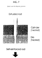
- FIGURE 7 shows schematically the arrangement of the solid state die-drawing process.
- FIGURE 3 shows a SEM figure of the surface of a self-reinforced P(L/DL)LA composite rod containing 20 wt. % of glass particles (draw ratio 3.3).
- Several spindle-shaped open pores are seen on the surface of the composite rod, and inside of every pore is a glass particle.
- the polymer skin above the glass particles, which are inside of surface pores, has ruptured during self-reinforcing (drawing) and free particle surfaces are exposed (two such particles are marked with white arrows).
- TABLE 3 shows the strength and modulus values for some of the studied self-reinforced ("SR") P(L/DL)LA composites containing the BG-13 particles.
- SR self-reinforced
- Samples 1 and 3a-3c were ductile in bending. Samples 2a-2b broke in bending, with a brittle mode.
- Lactide copolymer powder P(L/DL)LA 70/30 ( Resomer ® LR 708 (inherent viscosity of 5.5 dl/g, available from Boehringer Ingelheim, Ingelheim am Rhein, Germany) with different weight fractions (from 0 wt. % to 30 wt. %) of glass spheres of EXAMPLE 1 were mixed mechanically and poured into a hopper of a single screw extruder (model Gimac TR ⁇ 12/24 B.V.O, of MAC.GI SRL, Castronno, Italy). A nitrogen atmosphere (N 2 flow 5 1/min) was introduced in the hopper to avoid contact with the room's air.
- N 2 flow 5 1/min was introduced in the hopper to avoid contact with the room's air.
- the rotating screw together with friction of compression and heating of the hopper's outer surface, plasticized the thermoplastic material and pushed the polymer melt-glass powder mixture towards the barrel end and die orifice.
- Temperatures of the heating zones were 150°C-160°C-170°C-185°C-205°C and 221°C (at the die's orifice).
- the cylindrical extrudate rods with diameters 2-8 mm were precooled in a N 2 atmosphere and placed onto a transportation band for cooling to room temperature.
- Mechanical tests (bending) were done at room temperature for extruded rods (diameter of 3.5 mm) with different weight fractions of bioactive glass spheres (using the testing machine Instron 4411, Instron Ltd, England). Bending strength decreased from 125 MPa to 115 MPa and bending modulus increased from 2.2 GPa to 3.4 GPa when the portion of glass particles increased from 0 wt. % to 20 wt. %.
- FIGURE 5 shows a SEM micrograph of an extruded composite rod containing 17.5 ⁇ 2.5 wt. % of glass spheres of EXAMPLE 1. Glass spheres can be seen clearly below the polymer surface (skin). The composite rods with 0 wt. % of glass spheres showed ductile behavior in bending, while rods with 20 wt. % or more of glass spheres showed brittle behavior in bending.
- FIGURE 7 shows schematically the arrangement of the solid state die-drawing process. For optimum strength values the different draw temperatures and draw ratios were studied.
- Drawing temperatures for pure P(L/DL)LA rods were 70-75°C and for the P(L/DL)LA rods containing bioactive glass spheres they were 85-95°C.
- Draw ratios of 2-7 were studied. The drawing speed was 10 mm/min.
- FIGURE 6 shows a SEM figure of the surface of a self-reinforced P(L/DL)LA composite rod containing 20 wt. % of glass spheres (using a draw ratio of 3.3).
- Several spindle-shaped open pores are seen on the surface of the composite rod, and inside of every pore is a glass sphere.
- the polymer skin above the glass spheres (which are inside of surface pores) has ruptured during self-reinforcing (drawing) and free sphere surfaces are exposed.
- Bending strengths of P(L/DL)LA-bioactive glass sphere composite rods increased 20-50 % as a consequence of self-reinforcing.
- the bending strength of P(L/DL)LA containing 20 wt. % of BG-13 spheres increased from 117 MPa to 156 MPa after self-reinforcing by drawing (using a draw ratio of 3.9). All the materials were transformed from brittle to ductile ones as a consequence of self-reinforcing, even when porosity was developed in those materials.
- FIG. 8A shows a SEM figure of the internal structure of an extruded composite rod of P(L/DL)LA containing 17.5 ⁇ 2.5 wt. % of BG-13 glass spheres.
- the rod was split mechanically with a sharp knife and the exposed internal structure was studied by SEM.
- the glass spheres are in an intimate contact with the polymer matrix, which as such is practically non-porous.
- FIG. 8B shows the internal structure of the corresponding composite rod after self-reinforcing.
- the self-reinforced rod was split longitudinally and the exposed internal structure was studied by SEM.
- the draw direction is horizontal in FIG. 8B . Longitudinal orientation and self-reinforcing have created spindle-shaped pores around the glass spheres.
- a white arrow head shows a point where one pore has opened into another (second) pore so that the pores are connected with each other and a glass sphere (A) is exposed partially into the second pore that is located by the
- bioactive glasses dissolve partially (starting from the glass surface) and calcium phosphate or carbonated hydroxyapatite layer precipitations develop on the glass surface (see, e.g., M. Brink "Bioactive Glasses with a Large Working Range” Doctoral Thesis ⁇ bo Akademi University, Turku, Finland, 1997 , and M. Marcolongo et al. J. Biomed. Mater. Res. 39 (1998) 161 ).
- the formation of such precipitations is an indication of bioactive behavior of the bioabsorbable composite, and such precipitations are advantageous especially in bone surgery because they enhance new bone growth in close contact with the implant surface.
- Cylindrical samples (diameter 3 mm and length 15 mm) were placed into plastic pots filled with 200 ml of SBF. Sample solutions were kept at 37°C for one week. Surface reactions were examined from dried and carbon coated sample surfaces with SEM. The following samples were examined:
- this example demonstrated the bioactivity of the composites of the invention in vivo, after implantation in a bony environment.
- Polymeric composite rods containing a bioactive glass particle filler and all-polymer control specimens were implanted in rabbit femurs. Based on in vitro experiments, we assumed that the self-reinforced composite rods would form a bond to bone tissue, providing early fixation between the implant material and bone. Interfacial bond strengths between the implant materials and bone tissue were measured, and the mechanism of bone tissue incorporation into the composite material was investigated.
- Cylindrical samples with diameter of 3 mm and length of 15 mm were machined from both the extruded and the additionally self-reinforced materials designated as A through F in EXAMPLE 4.
- the implants were sterilized using gamma radiation with a dose of 2.5 Mrad.
- One composite and one control polymer or composite specimen were implanted bilaterally into 3 mm diameter drill holes in the distal femur of eight rabbits, using aseptic techniques.
- the rabbits were euthanized by injection of nembutal six weeks after the implantation, and each femur was harvested.
- the bones were cross sectioned in the region of the implant using saline as a cutting fluid, while maintaining the moisture in the samples.
- the implant/bone composite was then sectioned transverse to the long axis of the implant, leaving half of the implant/bone section for mechanical testing and the remaining half for histology.
- the implant was pushed out of bone and the interfacial bond strength between polymer or composite sample and bone was calculated using test arrangements described in Marcolongo et al., J. Biomed. Mater. Res. 39 (1998) pp. 161-170
- SR-composites showed close apposition to bone tissue at six weeks. Most of the composite surfaces had direct bone contact. Only about 20 % of the interface had thin fibrous tissue between the composite and bone.
- Pellets of copolymer material comprising about 80 mol-% of L-lactide and about 20 mol-% of glycolide (PLGA) were supplied by PURAC Biochem bv, Gorinchem, Holland.
- the pellets had an inherent viscosity of about 5.9 dl/g and a molecular weight M w of about 336,000. The inherent viscosity was measured at 25 °C using 100 mg polymer per 100 ml of chloroform.
- PLLA Poly-L-lactide
- Each polymer powder or granulate, PLGA, PDTHC, POE, PAH and PLLA was mixed mechanically with 25 wt. % of BG-13 spheres of EXAMPLE 1 and extruded to cylindrical bars with diameters of 2-8 mm, using a single screw extruder (Axon BX-15, Axon Permaskiner, Sweden).
- the composite rods were oriented and/or self-reinforced uniaxially by drawing them through a heated die at a temperature (T) of 20 to 40°C above the T g of the corresponding polymer.
- Composite rods with the draw ratio of 3 and diameter of 2.0-2.1 mm were selected for animal experiments.
- Corresponding oriented and/or self-reinforced PLGA, PDTHC, POE, PAH and PLLA rods (manufactured from the same raw polymer materials by extrusion and solid state drawing to the draw ratio of 3) were used as control rods. All the rods were sterilized with gamma radiation (2.5 Mrad dose).
- the patella was dislocated laterally and the distal end of the femur was exposed.
- a 2 mm drill hole was made through the intercondylar space.
- An osteotomy was done through the metaphysis leaving the posterior cortex intact to serve as a hinge.
- the wounds were closed with 4-0 USP PGA sutures (Dexon ® , Davis & Geck, USA).
- the rats Postoperatively, the rats were returned into their cages, where they recovered from anaesthesia. They were given a regular normal laboratory animal diet. They were followed-up for 1, 3, 6 and 12 weeks. Each follow-up group comprised 4 rats having the composite rods containing the BG-13 particles and 4 control rod rats. After sacrifice, both femurs were exarticulated. Immediate postoperative plain radiographs (anteroposterior and lateral views) were taken of both femora (taget tube distance 100 cm, exposure factors 40 kV, 5mA and 0.03s). The healing of the osteotomies was evaluated radiologically, histologically and with mechanical testing by shearing the fixed bone part along the osteotomy plane. The mechanical tests were done according to M. Manninen and T. Pohjonen, Biomaterials, 14 (1993) 305-312 .
- BG-composite rods and control rods 15 mm long and 2 mm in diameter were used.
- the rods were sterilized by gamma radiation.
- the rod packages were opened just before tests started. Wistar rats of both sexes, 12 weeks old and weighing 250-350 g, were operated on.
- medetomidine Domitor TM , Lääkefarmos, Turku, Finland
- 3 mg/300 g ketalar ketalar TM , Parke-Davis, Barcelona, Spain
- the rats Postoperatively, the rats were returned into their cages, where they recovered from anaesthesia. They were given a regular normal laboratory animal diet. They were followed-up for 1, 3, 6 and 12 weeks. After sacrifice, the rods were removed from the rats, and immediately after removal stored in saline. The shear strength tests were made within 24 h after death and immediately after removal from saline according to M. Manninen and T. Pohjonen, Biomaterials, 14 (1993) 305-312 .
- Shear breaking test of osteotomies at the 1 week follow-up period showed practically the same shear strength values for the osteotomies fixed with BG-13 composite rods as for those fixed with control rods.
- the osteotomies fixed with BG-13 composite rods exhibited ca. 20 ⁇ 5 % higher shear strength, at 6 weeks follow-up 25 ⁇ 5 % higher shear strength and at 12 weeks follow-up 15 ⁇ 5 % higher shear strength than the osteotomies fixed with control rods.
- Glass fibers (with diameter 113 um) of EXAMPLE 1 were coated with PLGA (described in EXAMPLE 6) by drawing a bundle of 20 continuous fibers through the polymer melt and by cooling the polymer-impregnated fiber bundle in air.
- the amount of glass fibers was 50 wt. % in the impregnated bundle.
- the bundle was cut to 3 mm long granules and these were mixed mechanically with pure PLGA powder so that the amount of glass fibers was 25 wt. % in the mixture.
- the mixture was melt extruded and self-reinforced into rods with diameter of 2 mm, using the procedure described in EXAMPLE 6 (the draw ratio of solid state drawing was 3.4).
- this example demonstrated that only self-reinforced porous, bioabsorbable polymer rods with bioactive glass fibers, exhibited bioactive behavior after two weeks' hydrolysis.
- the evident reason for this is that the glass fibers are exposed to the sample surface via the open surface pores only after self-reinforcing has broken the skin over the fibers, thereby opening the pores to the sample surface.
Landscapes
- Health & Medical Sciences (AREA)
- Chemical & Material Sciences (AREA)
- Epidemiology (AREA)
- Veterinary Medicine (AREA)
- Materials Engineering (AREA)
- Engineering & Computer Science (AREA)
- Composite Materials (AREA)
- Public Health (AREA)
- General Health & Medical Sciences (AREA)
- Animal Behavior & Ethology (AREA)
- Inorganic Chemistry (AREA)
- Life Sciences & Earth Sciences (AREA)
- Transplantation (AREA)
- Oral & Maxillofacial Surgery (AREA)
- Medicinal Chemistry (AREA)
- Dermatology (AREA)
- Heart & Thoracic Surgery (AREA)
- Surgery (AREA)
- Vascular Medicine (AREA)
- Materials For Medical Uses (AREA)
- Compositions Of Macromolecular Compounds (AREA)
Abstract
Description
- The invention relates to bioactive, biocompatible, bioabsorbable surgical composites and devices, such as pins, screws, plates, tacks, bolts, intramedullary nails, suture anchors, staples, or other devices which are applied in bone-to-bone, soft tissue-to-bone or soft tissue-to-soft tissue fixation or in fixation of bioabsorbable and/or biostable implants in, and/or on, bone or soft tissue, which composites and devices are fabricated of bioabsorbable polymers, copolymers or polymer alloys that are self-reinforced and contain ceramic particles or reinforcement fibers and porosity.
- Bioabsorbable surgical devices such as, e.g., pins, screws, plates, tacks, bolts, intramedullary nails, suture anchors, or staples, etc., made from bioabsorbable polymers are becoming more frequently used in the medical profession in bone-to-bone, soft tissue-to-bone or soft tissue-to-soft tissue fixation. Numerous publications describe the aforementioned and other bioabsorbable devices for such tissue fixation applications, e.g.,
U.S. Pat. No. 4,655,203 ,U.S. Pat. No. 4,743,257 ,U.S. Pat. No. 4,863,472 ,U.S. Pat. No. 5,084,051 ,U.S. Pat. No 4,968,317 ,EPO Pat. No. 449,867 U.S. Pat. No. 5,562,704 ,PCT/FI 96/00351 PCT/FI 96/00511 FI Pat. Appl. No. 965111 U.S. Pat. Appl. Serial No. 08/873,174 ,U.S. Pat. Appl. Serial No. 08/887,130 ,U.S. Pat. Appl. Serial No. 08/914,137 , andU.S. Pat. Appl. Serial No. 08/921,533 . - Surgeons would prefer to use bioabsorbable devices that eventually resorb and disappear from the body after they have served their purpose during tissue fixation and healing and, accordingly, are not needed any more. However, a device made from bioabsorbable polymer must have sufficient strength and stiffness for effective tissue fixation and it must retain sufficient strength to perform its function during the tissue healing process, before it eventually is absorbed by the body. It is advantageous to mix different additives into bioabsorbable polymers to modify their properties and to yield devices having useful properties. Such typical additives include ceramic, which optionally can be bioactive, particle fillers and short fiber reinforcements (having fiber lengths typically between 1 µm-10 mm), each of which can promote osteoconductivity of bioabsorbable bone fracture fixation devices, such as pins, screws or plates or other fixation implants like suture anchors and tacks, which are in contact with bone tissue.
- Bioactive, bioabsorbable ceramic fillers and fibers and/or their use in bioabsorbable devices as bioactive ceramic fillers and/or reinforcements have been described in several of the aforementioned publications, and also are describe in, e.g.,
EPO Pat. Appl. 0 146 398 ,U.S. Pat. No. 4,612,923 , andPCT Pat. Appl. WO 96/21628 - Ceramic particle fillers and/or short fiber reinforcements typically are first dry blended with bioabsorbable polymer powder, granulate or flakes, and the mixture is then melt blended in an extruder, injection molding machine or in a compression molding machine. The melt blended extrudate can be pelletized or cooled and crushed and sieved to the desired grain size. Such pellets or grains can be further melt processed, e.g., by extrusion, injection molding or compression molding, into bioabsorbable preforms or they can be used as masterbatches and mixed with nonblended bioabsorbable polymers and melt processed into bioabsorbable preforms which can be processed further mechanically and/or thermomechanically to make surgical devices. It also is possible to melt process many devices directly from pellets or grains or masterbatches of polymer mixtures, e.g., with extrusion, injection molding or compression molding.
- Particles or short fibers of bioactive glass, such as are described in
PCT Pat. Appl. WO 96/21628 - However, the surface of melt-molded bioabsorbable polymer composites containing bioactive glass filler and/or fiber reinforcements is coated with a "skin" of bioabsorbable polymer which prevents the immediate direct contact of glass particles with the surrounding tissues and tissue fluids when the melt molded device has been implanted into living tissue. The advantageous direct contact of bioactive glass particles with the tissue environment can develop only weeks or months after implantation when biodegradation of the polymeric surface layer (skin) has proceeded so far that cracks or crazes have developed in the surface layer of composite. Therefore, it is necessary to machine the surfaces of such melt molded composites mechanically to remove the isolating skin layer if immediate contact between glass particles (filler or fibers) is desired. Such a surface machining is, however, time consuming process.
- An additional general problem with ceramic particle filled thermoplastic polymer composites is their brittleness, because addition of ceramic fillers into the polymer matrix changes most thermoplastic polymers from tough and ductile to brittle in nature. This is evidenced by significant reduction of both elongation at break and impact strength (see, e.g., Modem Plastics, Guide to Plastics, 1987, McGraw-Hill, New York, pp. 152-153 and Modem Plastics Encyclopedia, Mid-October Issue 1989, McGraw-Hill, New York, 1989, pp. 600, 606-607, 608-609, 614). Moreover, even non-filled bioabsorbable thermoplastic polymer devices, which are manufactured by melt molding, may be brittle in their mechanical behavior. That brittleness can be a severe limitation on bioabsorbable devices, leading to premature breaking or to other adverse behavior (see, e.g., D. McGuire, et al., American Academy of Orthopaedic Surgeons, New Orleans, 65th Annual Meeting, March 19-23, 1998, Final Program, p. 261). Just as in nonbioabsorbable thermoplastic polymers, ceramic fillers also increase the brittleness of bioabsorbable polymers (see, e.g., Example 1 of this application).
- Additionally, the prior art bioabsorbable, particle filled or short fiber filled composites and devices made of them must have low porosities, because porosity weakens the composite and increases its brittleness. However, porosity also provides advantages to an implant which is in contact with bone or other tissue, because (bone) tissue can grow into the pores, accelerating new tissue (bone) formation and locking the implant into contact with the tissue (bone), thereby preventing implant migration. Such surface porosity also would facilitate the contact between the growing bone and ceramic particle or fiber fillers, if the ceramic particles or fibers are at least partially exposed into the pores.
- It would, therefore, be advantageous to have a strong and tough (nonbrittle), bioabsorbable composite comprising: (a) a matrix of a bioabsorbable polymer, copolymer (consisting of two or more monomer components) or polymer blend, which matrix is oriented and/or self-reinforced; (b) bioabsorbable, bioactive ceramic particles and/or short fiber filler or reinforcement dispersed in the polymer matrix; (c) pores which are dispersed in the polymer matrix and isolated or at least partially connected with one another, and into which pores at least some free surfaces of the particles or fibers are exposed; and (d) an outer surface comprising a polymer matrix, pores and ceramic particles and/or short reinforcing fibers, wherein a substantial amount of the ceramic particles or fibers have at least one free surface not covered by the polymer's skin.
- It would further be advantageous to have surgical implants manufactured of the composite described above, e.g., pins, screws, plates, tacks, bolts, intramedullary nails, suture anchors, staples, or other devices which can be applied in bone-to-bone, soft tissue-to-bone or soft tissue-to-soft tissue fixation or in fixation of bioabsorbable and/or biostable implants in and/or on bone or soft tissue. It also would be advantageous to have such surgical implants manufactured of the composites described above, which implants have pores and bioactive ceramic particles and/or short reinforcement fibers (fillers) that are in direct contact with the bone or tissue to which the implant is applied.
- The invention is surgical bioabsorbable composites and devices as defined in claim 1 and preferably comprises
- (a) a strong and tough (non-brittle) bioabsorbable partially crystalline polymeric matrix which is oriented and/or self-reinforced;
- (b) a bioabsorbable and/or bioactive particle and/or fiber filler phase dispersed in the polymer matrix;
- (c) pores dispersed in the polymer matrix, which pores include particles or fiber fillers with at least one surface exposed into the pore space; and
- (d) an outer surface, wherein the polymer matrix, pores and particles or short fiber fillers therein are at least partially in direct contact with their environment.
-
-
FIG. 1 is a scanning electron microscope (SEM) figure of particles of glass 13-93 (as used herein either "BG-13" or BG 13-93," and containing the following: Na2O - 6 wt. %; K2O - 12 wt. %; MgO - 5 wt. %; CaO - 20 wt. %; P2O5 - 4 wt. %; and SiO2 - 53 wt-%) sieved to the particle fraction 50-125 µm. -
FIG. 2 is a surface SEM figure of an extruded composite rod of P(L/DL)LA containing 17.5 ±2.5 wt. % of BG-13 glass particles, showing the polymeric skin on glass particles. The distance between scale bars (in the lower part of figure) is 100 µm. -
FIG. 3 is a surface SEM figure of a rod ofFIG. 2 after the rod has been self-reinforced by solid state drawing to a draw ratio of 3.3. White arrows show two glass particles inside of open pores on the outer surface of the rod. -
FIG. 4 is a SEM figure of glass BG-13 spheres sieved to a particle fraction of 50-125 µm. -
FIG. 5 is a surface SEM figure of an extruded P(L/DL)LA composite rod containing 17.5 ±2.5 wt. % of BG-13 glass spheres, showing the polymeric skin on glass spheres. -
FIG. 6 is a surface SEM figure of a rod ofFIG. 5 after the rod had been self-reinforced by solid state drawing to a draw ratio of 3.6. -
FIG. 7 is a schematic figure of the arrangement of the solid state die-drawing process. -
FIG. 8A is a SEM figure of internal structure of an extruded P(L/DL)LA composite rod containing 17.5 ± 2.5 wt. % of BG-13 glass spheres, andFIG. 8B is a SEM figure of internal structure of the corresponding composite rod after self-reinforcing by drawing (draw ratio 3.6). - The biopolymers employed in this invention are synthetic bioabsorbable polymers, copolymers and/or polymer alloys. Such polymers, like those made of poly-α-hydroxy acids and other aliphatic bioabsorbable polyesters, polyanhydrides, polyorthoesters, polyorganophosphatzenes, tyrosine polycarbonates and other bioabsorbable polymers are disclosed in several references mentioned above and also in many other publications, e.g., in
U.S. Pat. Appl. Serial No. 09/053, 670 ,U.S. Pat. Appl. Serial No. 09/036,259 ,U.S. Pat. Appl. Serial No. 09/033,475 ,U.S. Pat. Appl. Serial No. 09/055,005 ,U.S. Pat. Appl. Serial No. 08/997,458 ,U.S. Pat. Appl. Serial No. 09/054,672 , S. Vainionpää et al., Prog. Polym. Sci., 14 (1989) 679-716,FI Pat. No. 952884 FI Pat. No. 955547 WO-90/04982 EP 0449867 B1 ,U.S. Pat. No. 5,569,250 , S.I. Ertel et al., J. Biomed. Mater. Res., 29 (1995) 1337-1348, and P. Törmälä et al., Proc. Instn. Mech. Engrs Part H, 212 (1998) 101-111 - The absorbable bioactive glasses employed in the invention can be based on P2O5 as the network former, as in glasses described in
U.S. Pat. No. 4,612,923 and in prior art publications mentioned therein. - Such glasses typically can contain additionally at least one alkali or alkaline earth metal oxide, such as sodium oxide, potassium oxide, calcium oxide, magnesium oxide, and the like. Although the custom in the art is to refer to the constituents in the form of the oxides, the oxides per se need not be used in producing the glass. For instance, the following materials also can be used: (NH4)3PO4, (NH4)2HPO4, NaH2 PO2, KH2 PO4, CaCO3, Ca(H2 PO4)2, MgCO3, P2O5 MgHPO4, Zn3 (PO4)2 and MgO. As a general rule, the solubility rate (in aqueous media) is increased by increasing the proportion of alkali metal oxides (e.g.,. Na2 O and K2O), and is decreased by increasing the proportion of alkaline earth metal oxides (e.g., CaO and MgO). Thus, within certain limits, the solubility rate of the glass can be varied. Other oxides also can be added, in small amounts, if desired. For example, small amounts of SiO2, B2O3, and/or ZnO can be added for the purpose of retarding the dissolution rate for certain applications, or for enhancing processability.
- Bioactive glasses and glass-ceramics, like those described in the Doctoral Thesis of M. Brink (see supra) and in references therein on pages 9-10 and as described by M. Marcolongo et al. (J. Biomed. Mater. Res., 39 (1998) 161-170 can be employed in this invention. Naturally, the invention is not limited to those bioactive, bioabsorbable glasses described herein, but also other glasses can be used in this invention.
- Suitable glasses are produced by fusing the ingredients in the desired proportions in a platinum or a dense alumina crucible. Typical fusion temperatures are 800° to 1400 °C, and typical fusion times are about one to four hours. After fusion, the molten glass may be quenched, and then subjected to pulverizing to reduce the glass to a very fine particle size. The pulverizing of the glass can be done by known procedures such as air jet milling, ball milling, or the like. Typically, the powders used are of very fine particle size, e.g., below 200 mesh and in some cases below 400 mesh (Tyler Standard Sieve Series). It is also within the scope of the invention to employ the glass in the form of fibers (preferably as short fibers, e.g., fibers having diameters of from about 2 to 200 µm (microns) and aspect ratios [length/diameter] of about 1 to 100). The fibers can be made by known methods such as melt spinning.
- The proportion of glass filler and/or reinforcement in the polymer can vary from case to case, but will usually be within the range of from about 10 to about 60 weight per cent (wt-%), based on the weight of the filled polymer. In any event, the exact proportion of glass filler is not narrowly critical. The glass is employed in an amount sufficient to increase the bioactivity of the composite.
- The glass is incorporated in the polymer matrix by conventional procedures for adding fillers or short fibers to polymers. For instance, polymer pellets and glass powder or fibers, are intimately mixed in a blender, and the mixture is then compounded through an extruder. Injection or compression molding techniques can also be used. The glass can also be used in the form of continuous filaments, and rods comprising the continuous filament glass embedded in a matrix of absorbable polymer can be produced by the extrusion technique known as "pultrusion," wherein the polymer is continuously extruded around glass filaments that are pulled through the extruder nozzle. Such rods can then be granulated (chopped or cut to any desired length, after the pultrusion operation) for further use in manufacturing short fiber reinforced preforms or devices by compression molding, extrusion or injection molding. Such preforms can then be oriented and/or self-reinforced with solid state deformation, like with free or die drawing, biaxial drawing, compression, hydrostatic extrusion or ram extrusion as combined with drawing.
- Orientation and/or self-reinforcing techniques, which can be applied to manufacture the materials of the invention have been described in many publications, like in
U.S. Pat. No. 4,968,317 ,EPO Pat. No. 0 423 155 ,EPO Pat. No. 0 442 911 ,FI Pat.. No. 88111 FI Pat. No. 98136 U.S. Pat. Appl. Serial No. 09/036,259 ,U.S. Pat. No. 4,898,186 , and inU.S. Pat. Appl. Serial No. 09/036,259 . - In this invention we have found surprisingly that by applying drawing-, compression-or shear-type solid state orientation and/or self-reinforcing to bioabsorbable polymeric composites that include bioactive, bioabsorbable ceramic filler and/or short fiber reinforcement, it is possible to manufacture oriented and/or self-reinforced composites which are:
- strong and tough;
- bioactive (e.g., enhance new bone formation);
- porous; and
- have pores and partially exposed filler particles and/or short fibers on their outer surface.
- The new composites of the invention, when used as surgical implants or as components thereof enhance new bone formation both in their surroundings and into the pores of the implant, leading to more rapid healing and fixation of the device than in prior art devices.
- Surgical devices made from the composites of the invention, like pins, rods, intramedullary nails, screws, tacks, bolts, tissue and suture anchors, plates, meshes, fibers, threads, cords, felts, fabrics, scaffolds, membranes, etc., can be applied as temporary fixation implants in bone-to-bone, soft tissue-to-bone and soft tissue-to-soft tissue fixation, and also in tissue augmentation procedures and in guided tissue regeneration.
- Implants in accordance with the invention can be manufactured of bioabsorbable polymers by using one polymer or a polymer alloy. The implants also can be reinforced additionally by fibers manufactured of a resorbable polymer or of a polymer alloy, or with other biodegradable glass fibers, or ceramic fibers, such as β-tricalsiumphosphate fibers, bioglass fibers or CaM fibers (see, e.g.,
EP146398 - Implants according to the invention can also contain layered parts comprising, e.g., (a) a flexible outer layer as a surface layer improving the toughness and/or operating as the hydrolysis barrier and (b) a stiff inner layer.
- It is natural that the materials and implants of the invention can also contain various additives for facilitating the processability of the material (e.g., stabilizers, antioxidants or plasticizers) or for changing its properties (e.g., plasticizers or ceramic powder materials or biostable fibers, such as carbon) or for facilitating its treatment (e.g., colorants). According to one advantageous embodiment of the invention, the composite also contains other bioactive agent or agents, such as antibiotics, chemotherapeutic agents, agents activating healing of wounds, growth factor(s), bone morphogenic protein(s), anticoagulants (such as heparin), etc. Such bioactive implants are particularly advantageous in clinical use, because they have, in addition to their mechanical effect and bone growth stimulating effects, other biochemical, medical and other effects to facilitate tissue healing and/or regeneration.
- A typical manufacturing procedure to make devices of the present invention is as follows:
- First the polymer raw material and filler(s) and/or reinforcing fibers and optional additives in the form of a powder, flakes, pellets or granulate, etc., are melted with a continuous process, like extrusion, or with a noncontinuous process, like injection molding or compression molding. The melted material is cooled so that it solidifies to an amorphous or partially crystalline (crystallinity typically 5-50%) preform, like a cylindrical rod or bar, a flat balk with a rectangular cross-section, a plate or a sheet stock. Cooling can be done inside a mold when using injection molding or compression molding techniques. In extrusion, the preform is formed from the material melt in a die, and the preform is then passed onto a cooling belt or into a cooling solution to make a solid preform.
- Thereafter, the solid preform is oriented and/or self-reinforced with an uni- and/or biaxial solid state deformation process to create an oriented preform. The self-reinforcing or orientation transforms the preform stock into a strong, tough and partially porous form. The orientation is typically accomplished at a temperature (T) above the Tg (the glass transition temperature) of the polymeric raw material, but below the melting temperature of the material, if it is partially crystalline, and the orientation is typically made by drawing the unoriented preform in the solid state. The drawing can be done freely by fixing the ends of the preform into fixing clamps of a drawing machine, tempering the system to the desired drawing temperature, and increasing the distance between the fixing clamps so that the preform is stretched and oriented structurally. This type of orientation is mainly uniaxial. The drawing can be done also through a conical die, which can have, e.g., a circular, an ellipsoidal, a square, a star-like or rectangular cross-section. When the cross-sectional area of the bioabsorbable polymer billet, which will be drawn through the die, is bigger than the cross-sectional area of the die outlet, the billet is deformed and oriented uni- and/or biaxially during drawing, depending on the geometry of billet and die.
- In addition to drawing, pushing deformation can also be applied to the billet. For example, the billet may be forced through the die by drawing and at the same time by pushing the billet mechanically with a piston through the die (ram extrusion) or by pushing the billet through the die with hydrostatic pressure (see, e.g., N. Inoue, in Hydrostatic Extrusion, N. Inoue and M. Nishihara (eds.), Elsevier Applied Science Publishers, Barbing, England, 1985, p. 333-362).
- It also is possible to create orientation by shearing the flat billet between two flat plates which glide in relation to each other and approach each other at the same time, as is described in
U.S. Pat. Appl. Serial No. 09/036,259 . It also is possible to deform the billet in a compression molding device between flat plates which are pushed towards each other so that the billet deforms biaxially between the plates and attains the desired final thickness. The deformation can be done also by rolling the rod-like or plate-like preform between rollers, which flatten the preform to the desired thickness orienting the material at the same time biaxially. The rolling can be combined with drawing, e.g., by using two pairs of rollers positioned one pair after the other, which rollers have different rolling speeds. The billet and/or die, compression plates or rolls can be heated to the desired deformation temperature with electrical heating or with a suitable heating medium, like a gas or heating liquid. The heating can be done also with microwaves or ultrasonically to accelerate the heating of the billet. Regardless of the deformation method, the purpose of the solid state deformation is the orientation of the material uni- and/or biaxially so that the material is transformed into a strong and ductile one and porosity is created around the filler and/or reinforcement particles, spheres or fibers, thus enhancing the interaction of filler and/or reinforcement with its environment. - Following the orientation step, surgical devices can be formed from the oriented preforms by machining, stamping, thermoforming or with other mechanical, thermal or thermomechanical methods. After finishing, cleaning and drying, the surgical devices of the invention can be packed into a plastic foil and/or aluminum foil pouches which are sealed. Another drying step and filling of the pouch with an inert gas (like nitrogen or argon gas), before heat sealing of the pouch, may also be carried out.
- In the next step the devices closed into the packages, are sterilized with γ-radiation, using a standard dose of radiation (e.g., 2.5-3.5 MRad). If gas sterilization (like ethylene oxide) or plasma sterilization, will be used , the devices must be sterilized before closing the package.
- Naturally, the above-mentioned steps of manufacturing devices of the present invention may further include additional steps, such as for quality control purposes. These additional steps may include visual or other types of inspections during or between the various steps, as well as final product inspection including chemical and/or physical testing and characterization steps, as well as other quality control testing.
- The following examples describe some important embodiments of the invention.
- Bioactive glass 13-93 was manufactured according to
PCT Pat. Appl. WO 96/21628 - Raw materials (Na2CO3, CaCO3, CaHPO 4*2H 2O, SiO2, MgO, K2CO3) were measured as powders, mixed and melted in a platinum crucible at 1360°C for 3 + 3 hours to form bulk glass. Bulk glass was then used for manufacturing of particles, spherical particles and fibers.
- Bulk glass was crushed in an agate (99.9 % SiO2) grinding bowl with agate grinding balls in a planetary mill (Fritch Pelverisette 5, Germany). Agate bowl and balls were used to avoid glass contamination during grinding.
- Particles (see
FIGURE 1 ) were sieved to the particle fraction 50-125µm and washed with ethanol. - The grinded and irregularly shaped glass particles were transformed into spherical ones by flame spraying (see M. Brink et al., Bioceramics, 9, 1996, pp. 127-130). In the flame spraying process, the glass particles are fed into the spray gun and then sprayed with a carrier gas in the flame, where they melt. The spherical particles are then collected into a container. Pressurized air was used as a carrier gas for the particles. The flame consisted of a mixture of acetylene and oxygen. The particle size distribution used in flame spraying was 50-125 µm. The bioactivity of the glass 13-93 was maintained during and after the sphere manufacturing process.
-
FIGURE 4 shows spherical glass particles of 50-125 µm manufactured with the flame spraying process. - The continuous glass fibers were manufactured by a melt spinning (drawing) process using bioactive glass 13-93.
- Glass particles were heated in a platinum crucible to the temperature where the viscosity range for fiber drawing is achieved (< 1000°C, about 30-60 min). A platinum crucible with 4 orifices, approx. diameter 3,6 mm, at the bottom was used. The viscous glass melt formed drops at the crucible orifices. When the drops started to fall they were caught/touched and pulled to form the fibers and attached to the take-up wheel. By varying the spinning velocity the fiber diameter could be modified.
- Glass fibers with diameters of about 63 µm and 113 µm were manufactured and their tensile strength and modulus were determined.
- The fibers (ten specimens) were tested just after fiber spinning in air at room temperature with a tensile testing machine (Instron 4411, Instron Ltd, England) at a cross head speed of 20 mm/min (standard recommendation: ASTM D 3379-75, Standard Test Method for Young's Modulus for High-Modulus Single-Filament Materials). TABLE 1, below, gives fiber tensile strength and modulus values as recorded.
TABLE 1 Average diameter (µm) Average tensile strength (MPa) Standard deviation Modulus (Gpa) Standard deviation 63 849 204 43.2 10.2 113 727 214 44.4 7.5 - Lactide copolymer powder P(L/DL)LA 70/30 (Resomer® LR 708 (inherent viscosity of 5.5 dl/g, available from Boehringer Ingelheim, Ingelheim am Rhein, Germany) with different weight fractions (from 0 wt. % to 30 wt. %) of glass particles of EXAMPLE 1 were mixed mechanically and poured into a hopper of a single screw extruder (model Gimac TR ø 12/24 B.V.O, of MAC.GI SRL, Castronno, Italy). A nitrogen atmosphere (N2 flow 5 1/min) was supplied to the hopper to avoid contact with the room's air. The rotating screw, together with friction of compression and heating of the outside of the hopper, plasticized the thermoplastic material and pushed the polymer melt-glass powder mixture towards the barrel end and die orifice. Temperatures of the heating zones (from feed zone to die orifice) were 150°C-160°C-170°C-185°C-205°C and 221°C (at the die orifice).
- The cylindrical extrudate rods with diameters of 2-8 mm were precooled in a N2 atmosphere and placed on a transportation band for cooling to room temperature. Mechanical tests (bending) were done at room temperature for extruded rods (diameter of 3.5 mm) with different weight fractions of bioactive glass particles (using the testing machine designated Instron 4411, available from Instron Ltd, England). Bending strength decreased from 117 MPa to 112 MPa and bending modulus increased from 2.3 GPa to 3.2 GPa when the portion of glass particles increased from 0 wt. % to 20 wt-%.
-
FIGURE 2 shows a SEM micrograph of an extruded composite rod with 17.5 ± 2.5 wt. % of glass particles of EXAMPLE 1. Glass particles can be seen clearly below the polymer surface (skin). The composite rods with 0 wt. % of glass particles showed ductile behavior in bending while rods with 20 wt. % or more of glass particles showed brittle behavior in bending. - Extruded P(L/DL)LA and P(L/DL)LA -bioactive glass composite rods were self-reinforced using a solid state die-drawing process.
-
FIGURE 7 shows schematically the arrangement of the solid state die-drawing process. - For optimum strength values the different draw temperatures and draw ratios were studied. Drawing temperatures for the pure P(L/DL)LA rods were 70-75 °C and for the P(L/DL)LA rods containing bioactive glass (BG-13) particles they were 85-95°C. Draw ratios of 2-7 were studied. The drawing speed was 10 mm/min. A tensile testing machine designated JJ T5003, available from Lloyd Instruments Ltd, England, was used for drawing the rods fixed at both ends to clamps of that drawing machine.
-
FIGURE 3 shows a SEM figure of the surface of a self-reinforced P(L/DL)LA composite rod containing 20 wt. % of glass particles (draw ratio 3.3). Several spindle-shaped open pores are seen on the surface of the composite rod, and inside of every pore is a glass particle. The polymer skin above the glass particles, which are inside of surface pores, has ruptured during self-reinforcing (drawing) and free particle surfaces are exposed (two such particles are marked with white arrows).
TABLE 3 shows the strength and modulus values for some of the studied self-reinforced ("SR") P(L/DL)LA composites containing the BG-13 particles.TABLE 3. Strength and modulus values of P(L/DL)LA, SR-P(L/DL)LA and their composites with bioactive glass particles. Sample No. Material Bending strength (MPa) Bending modulus (Gpa) Draw ratio (1) P(L/DL)LA 117 2.3 -- (2) P(L/DL)LA composites: (2) (a) 10 wt. % of glass 13-93 particles 92 2.4 -- (2) (b) 25 wt-% of glass 13-93 particles 98 3.7 -- (3) SR-P(L/DL)LA composites: (3) (a) 0 wt-% of glass 13-93 particles 178 3.7 4.4 (3) (b) 10 wt-% of glass 13-93 particles 160 3.7 4.2 (3) (c) 20 wt-% of glass 13-93 particles 139 3.3 4.7 - Samples 1 and 3a-3c were ductile in bending. Samples 2a-2b broke in bending, with a brittle mode.
- Lactide copolymer powder P(L/DL)LA 70/30 ( Resomer® LR 708 (inherent viscosity of 5.5 dl/g, available from Boehringer Ingelheim, Ingelheim am Rhein, Germany) with different weight fractions (from 0 wt. % to 30 wt. %) of glass spheres of EXAMPLE 1 were mixed mechanically and poured into a hopper of a single screw extruder (model Gimac TR ø 12/24 B.V.O, of MAC.GI SRL, Castronno, Italy). A nitrogen atmosphere (N2 flow 5 1/min) was introduced in the hopper to avoid contact with the room's air. The rotating screw, together with friction of compression and heating of the hopper's outer surface, plasticized the thermoplastic material and pushed the polymer melt-glass powder mixture towards the barrel end and die orifice. Temperatures of the heating zones (from feed zone to die orifice) were 150°C-160°C-170°C-185°C-205°C and 221°C (at the die's orifice).
- The cylindrical extrudate rods with diameters 2-8 mm were precooled in a N2 atmosphere and placed onto a transportation band for cooling to room temperature. Mechanical tests (bending) were done at room temperature for extruded rods (diameter of 3.5 mm) with different weight fractions of bioactive glass spheres (using the testing machine Instron 4411, Instron Ltd, England). Bending strength decreased from 125 MPa to 115 MPa and bending modulus increased from 2.2 GPa to 3.4 GPa when the portion of glass particles increased from 0 wt. % to 20 wt. %.
-
FIGURE 5 shows a SEM micrograph of an extruded composite rod containing 17.5 ± 2.5 wt. % of glass spheres of EXAMPLE 1. Glass spheres can be seen clearly below the polymer surface (skin). The composite rods with 0 wt. % of glass spheres showed ductile behavior in bending, while rods with 20 wt. % or more of glass spheres showed brittle behavior in bending. - Extruded P(L/DL)LA and P(L/DL)LA composite rods containing bioactive glass spheres were self-reinforced ("SR") by a solid state die-drawing process.
-
FIGURE 7 shows schematically the arrangement of the solid state die-drawing process. For optimum strength values the different draw temperatures and draw ratios were studied. - Drawing temperatures for pure P(L/DL)LA rods were 70-75°C and for the P(L/DL)LA rods containing bioactive glass spheres they were 85-95°C. Draw ratios of 2-7 were studied. The drawing speed was 10 mm/min. The instrument designated JJ T5003, Lloyd Instruments Ltd, England, was used for the drawing process.
-
FIGURE 6 shows a SEM figure of the surface of a self-reinforced P(L/DL)LA composite rod containing 20 wt. % of glass spheres (using a draw ratio of 3.3). Several spindle-shaped open pores are seen on the surface of the composite rod, and inside of every pore is a glass sphere. The polymer skin above the glass spheres (which are inside of surface pores) has ruptured during self-reinforcing (drawing) and free sphere surfaces are exposed. - Bending strengths of P(L/DL)LA-bioactive glass sphere composite rods increased 20-50 % as a consequence of self-reinforcing. For example, the bending strength of P(L/DL)LA containing 20 wt. % of BG-13 spheres increased from 117 MPa to 156 MPa after self-reinforcing by drawing (using a draw ratio of 3.9). All the materials were transformed from brittle to ductile ones as a consequence of self-reinforcing, even when porosity was developed in those materials.
-
FIG. 8A shows a SEM figure of the internal structure of an extruded composite rod of P(L/DL)LA containing 17.5 ± 2.5 wt. % of BG-13 glass spheres. The rod was split mechanically with a sharp knife and the exposed internal structure was studied by SEM. The glass spheres are in an intimate contact with the polymer matrix, which as such is practically non-porous.FIG. 8B shows the internal structure of the corresponding composite rod after self-reinforcing. The self-reinforced rod was split longitudinally and the exposed internal structure was studied by SEM. The draw direction is horizontal inFIG. 8B . Longitudinal orientation and self-reinforcing have created spindle-shaped pores around the glass spheres. A white arrow head shows a point where one pore has opened into another (second) pore so that the pores are connected with each other and a glass sphere (A) is exposed partially into the second pore that is located by the sphere's original pore. - All the materials which were brittle in bending before self-reinforcing were ductile in bending after self-reinforcing.
- In hydrolytic conditions in simulated body fluid, bioactive glasses dissolve partially (starting from the glass surface) and calcium phosphate or carbonated hydroxyapatite layer precipitations develop on the glass surface (see, e.g., M. Brink "Bioactive Glasses with a Large Working Range" Doctoral Thesis Åbo Akademi University, Turku, Finland, 1997, and M. Marcolongo et al. J. Biomed. Mater. Res. 39 (1998) 161). The formation of such precipitations is an indication of bioactive behavior of the bioabsorbable composite, and such precipitations are advantageous especially in bone surgery because they enhance new bone growth in close contact with the implant surface.
- In this example, we studied the bioactive behavior of materials of the invention in comparison to the behavior of prior art materials by examining the degradation of polymeric and composite samples in simulated body fluid (SBF) (see T. Kokubo et al. in Bioceramics, Vol. 2, ed. G. Heimke, Deutsche Keramische Gesellschaft e.V., Cologne, Germany, 1990 pp. 235-242).
- Cylindrical samples (diameter 3 mm and length 15 mm) were placed into plastic pots filled with 200 ml of SBF. Sample solutions were kept at 37°C for one week. Surface reactions were examined from dried and carbon coated sample surfaces with SEM.
The following samples were examined: - (A) Extruded P(L/DL)LA (70/30) rod;
- (B) Self-reinforced ("SR" as used herein) P(L/DL)LA (70/30) rod (draw ratio of 3.3);
- (C) Extruded composite rod: P(L/DL)LA (70/30) with 20 wt. % of glass BG-13 particles
- (D) Extruded composite rod: P(L/DL)LA (70/30) with 20 wt. % of glass BG-13 spheres
- (E) Material C as self-reinforced (draw ratio = 3.3)
- (F) Material D as self-reinforced (draw ratio = 3.3)
- Rod surface reactions were examined with SEM after 4 weeks immersion of samples in SBF. Results are given in TABLE 4.
TABLE 4. Sample Surface Reactions A No significant changes B No significant changes C No significant changes D No significant changes E Calcium phosphate precipitations around pores F Calcium phosphate precipitations around pores - This example demonstrated that only self-reinforced, porous, bioabsorbable polymer rods (samples E and F) with bioactive glass particles and spheres, exhibited bioactive behavior after four weeks of hydrolysis in the SBF. The evident reason for this is that the glass particles or spheres are exposed to the sample surface via the open surface pores only, after self-reinforcing has broken the skin over the particles and opened the pores to the sample surface.
- After showing in the above example the bioactivity of the materials of the invention in vitro, this example demonstrated the bioactivity of the composites of the invention in vivo, after implantation in a bony environment.
- Polymeric composite rods containing a bioactive glass particle filler and all-polymer control specimens were implanted in rabbit femurs. Based on in vitro experiments, we assumed that the self-reinforced composite rods would form a bond to bone tissue, providing early fixation between the implant material and bone. Interfacial bond strengths between the implant materials and bone tissue were measured, and the mechanism of bone tissue incorporation into the composite material was investigated.
- Cylindrical samples with diameter of 3 mm and length of 15 mm were machined from both the extruded and the additionally self-reinforced materials designated as A through F in EXAMPLE 4. The implants were sterilized using gamma radiation with a dose of 2.5 Mrad. One composite and one control polymer or composite specimen were implanted bilaterally into 3 mm diameter drill holes in the distal femur of eight rabbits, using aseptic techniques. The rabbits were euthanized by injection of nembutal six weeks after the implantation, and each femur was harvested. The bones were cross sectioned in the region of the implant using saline as a cutting fluid, while maintaining the moisture in the samples. The implant/bone composite was then sectioned transverse to the long axis of the implant, leaving half of the implant/bone section for mechanical testing and the remaining half for histology. The implant was pushed out of bone and the interfacial bond strength between polymer or composite sample and bone was calculated using test arrangements described in Marcolongo et al., J. Biomed. Mater. Res. 39 (1998) pp. 161-170
- TABLE 5 gives interfacial bond strengths between samples A-F and bone.
TABLE 5. Sample Interfacial bond strength A 4 ± 0.4 N B 4.6 ± 0.5 N C 4.5 ± 0.6 N D 4.7 ± 0.4 N E 8.8 ± 0.6 N F 9.0 ± 0.8 N - TABLE 5 shows that the self-reinforced composite rods E and F, which had pores open to the surface of the implant with bioactive glass particles in those pores, exhibited about two times higher interfacial bond strengths in comparison to polymer samples A and B and to composite samples C and D, which had a thin polymer skin covering bioactive glass particles or spheres.
- Histologically, the surfaces of SR-composites (samples E and F) showed close apposition to bone tissue at six weeks. Most of the composite surfaces had direct bone contact. Only about 20 % of the interface had thin fibrous tissue between the composite and bone.
- The respective interfaces between the sample and bone in samples A and B were mostly interposed by fibrous tissue, and in samples C and D more than half of their respective interfaces were fibrous.
- This in vivo study showed that self-reinforced composite samples E and F (containing pores open to the surface of the implant and bioactive glass particles in those pores) enhanced new bone formation significantly better than polymeric samples A and B (which had no bioactive ceramic filler) and composite samples C and D, each having a polymeric skin covering bioactive glass particles and spheres.
- This example demonstrated the effect of bioactive implants of the invention on healing of bone fractures (osteotomies).
- Pellets of copolymer material comprising about 80 mol-% of L-lactide and about 20 mol-% of glycolide (PLGA) were supplied by PURAC Biochem bv, Gorinchem, Holland. The pellets had an inherent viscosity of about 5.9 dl/g and a molecular weight Mw of about 336,000. The inherent viscosity was measured at 25 °C using 100 mg polymer per 100 ml of chloroform.
- Thermoplastic, bioabsorbable pseudo-polyaminoacid poly (DTH carbonate) (PDTHC) (Mw = 200,000) was synthesized according to S.I. Ertel and J. Kohn, J. Biomed. Mater. Res. 28 (1994) 919-930 and F.H. Silver et al., J. Long-Term Effects Med. Implants 1 (1992) 329-346.
- Thermoplastic, bioabsorbable polyorthoester (POE) (Mw = 80,000) was synthesized from diketene acetal, diols of trans-cyclohexane dimethanol and 1,6 -hexanediol (60/40 ratio of diols) according to Daniels, A.U. et al., Trans. Soc. Biomater. 12 (1989) 235 and Daniels, A.U. et al, Trans. Soc. Biomater. 12 (1989) 74.
- Thermoplastic, bioabsorbable polyanhydride (PAH) (Mw = 20,000) was synthesized from 1,3 bis (p-carboxyphenoxy) propane and sebacic acid according to
U.S. Pat. No. 5,618,563 , Example 1. - Poly-L-lactide (PLLA) (Mw = 700,000) was supplied by PURAC biochem bv, Gorinchem, Holland. Each polymer powder or granulate, PLGA, PDTHC, POE, PAH and PLLA was mixed mechanically with 25 wt. % of BG-13 spheres of EXAMPLE 1 and extruded to cylindrical bars with diameters of 2-8 mm, using a single screw extruder (Axon BX-15, Axon Plastikmaskiner, Sweden). The composite rods were oriented and/or self-reinforced uniaxially by drawing them through a heated die at a temperature (T) of 20 to 40°C above the Tg of the corresponding polymer. Draw ratios between 2-3 were studied for POE and PAH and draw ratios of 2-6 for PLGA, PDTHC and PLLA. SEM figures of composite rod surfaces showed analogous open surface pores with BG-13 spheres therein, as in the self-reinforced P(L/DL)LA rods of EXAMPLE 3.
- Composite rods with the draw ratio of 3 and diameter of 2.0-2.1 mm were selected for animal experiments. Corresponding oriented and/or self-reinforced PLGA, PDTHC, POE, PAH and PLLA rods (manufactured from the same raw polymer materials by extrusion and solid state drawing to the draw ratio of 3) were used as control rods. All the rods were sterilized with gamma radiation (2.5 Mrad dose).
- For each type of (glass particle-containing) composite rods and the control rods (based on PLGA, PDTHC, POE, PAH and PLLA polymers) an animal study was done to study bioactive behavior of the rods in vivo. In each case, the bioactive BG-13 containing composite rods and control rods were used in fixation of osteotomies of distal metaphysis of femurs in rats, in the following way. The right knee of a Wistar rat was shaved and sterilized with Neo-Amisept®. Wistar rats of both sexes, 12 weeks old and weighing 250-350 g were used. The rats received CO2 by inhalation, for induction, and anaesthesia was continued with 0.1 mg/300 g medetomidine (Domitor™, Lääkefarmos, Turku, Finland) and 3 mg/300 g ketalar (Ketalar™, Parke-Davis, Barcelona, Spain) by subcutaneous injections. An incision was made through the medial side to open the knee. The patella was dislocated laterally and the distal end of the femur was exposed. A 2 mm drill hole was made through the intercondylar space. An osteotomy was done through the metaphysis leaving the posterior cortex intact to serve as a hinge. A self-reinforced BG-13 containing composite rod or a self-reinforced control rod, having diameter of 2.0 - 2.1 mm and length of 15 mm, was introduced through the hole to fix the osteotomy. The wounds were closed with 4-0 USP PGA sutures (Dexon®, Davis & Geck, USA).
- Postoperatively, the rats were returned into their cages, where they recovered from anaesthesia. They were given a regular normal laboratory animal diet. They were followed-up for 1, 3, 6 and 12 weeks. Each follow-up group comprised 4 rats having the composite rods containing the BG-13 particles and 4 control rod rats. After sacrifice, both femurs were exarticulated. Immediate postoperative plain radiographs (anteroposterior and lateral views) were taken of both femora (
taget tube distance 100 cm, exposure factors 40 kV, 5mA and 0.03s). The healing of the osteotomies was evaluated radiologically, histologically and with mechanical testing by shearing the fixed bone part along the osteotomy plane. The mechanical tests were done according to M. Manninen and T. Pohjonen, Biomaterials, 14 (1993) 305-312. - In order to eliminate the effect of the fixation rod on the shear strength of osteotomy, the in vivo shear strength retention of the BG-13 composite rods and control rods was studied in the following way. BG-composite rods and control rods 15 mm long and 2 mm in diameter were used. The rods were sterilized by gamma radiation. The rod packages were opened just before tests started. Wistar rats of both sexes, 12 weeks old and weighing 250-350 g, were operated on. The rats received CO2 by inhalation, for induction, and anaesthesia was continued with 0.1 mg/300 g medetomidine (Domitor™, Lääkefarmos, Turku, Finland) and 3 mg/300 g ketalar (ketalar™, Parke-Davis, Barcelona, Spain) by subcutaneous injections. Four BG-13 composite rods or four control rods were implanted in the dorsal subcutaneous tissue of 32 rats, through 4 separate wounds. The wounds were closed with a 4-0 USP PGA sutures (Dexon®, Davis + Geck, USA).
- Postoperatively, the rats were returned into their cages, where they recovered from anaesthesia. They were given a regular normal laboratory animal diet. They were followed-up for 1, 3, 6 and 12 weeks. After sacrifice, the rods were removed from the rats, and immediately after removal stored in saline. The shear strength tests were made within 24 h after death and immediately after removal from saline according to M. Manninen and T. Pohjonen, Biomaterials, 14 (1993) 305-312.
- The effect of the fixation rod on the shear load carrying capacity of the healing osteotomy at each follow-up period was eliminated by reducing from the total shear load carrying capacity of the healing osteotomy and fixation rod system the shear load carrying capacity of the fixation pin (which value was determined from shear strength measurements of corresponding pins implanted subcutaneously). After 3 and 6 weeks' follow-up periods, radiological and histological examination showed a qualitatively more intense new bone formation in the drill channel and in the osteotomy area of femurs fixed with BG-13 composite rods than in femurs fixed with control rods.
- Shear breaking test of osteotomies at the 1 week follow-up period showed practically the same shear strength values for the osteotomies fixed with BG-13 composite rods as for those fixed with control rods. However, at the 3 week follow-up period, the osteotomies fixed with BG-13 composite rods exhibited ca. 20 ± 5 % higher shear strength, at 6 weeks follow-up 25 ± 5 % higher shear strength and at 12 weeks follow-up 15 ± 5 % higher shear strength than the osteotomies fixed with control rods.
- After 1 and 3 weeks follow-up, there were no obvious differences between the new bone formation in animals whose osteotomies were fixed with the various BG-13 composite rods, but after 6 and 12 weeks follow-up (based on radiological and histological examination) the new bone formation seemed to be most intense in PDTHC/BG-13 composite rod group and the intensity in the other BG-13 composite rods was smaller in the order: PLLA, POE, PLGA and PAH-group.
- This experiment showed that BG-13 composite rods enhanced early bone formation and fracture healing better than the control rods.
- Glass fibers (with diameter 113 um) of EXAMPLE 1 were coated with PLGA (described in EXAMPLE 6) by drawing a bundle of 20 continuous fibers through the polymer melt and by cooling the polymer-impregnated fiber bundle in air. The amount of glass fibers was 50 wt. % in the impregnated bundle. The bundle was cut to 3 mm long granules and these were mixed mechanically with pure PLGA powder so that the amount of glass fibers was 25 wt. % in the mixture. The mixture was melt extruded and self-reinforced into rods with diameter of 2 mm, using the procedure described in EXAMPLE 6 (the draw ratio of solid state drawing was 3.4).
- SEM examination of rod surfaces showed that glass fibers had broken during extrusion and solid state drawing to the lengths mainly between 150 µm -1.5 mm. The fibers were oriented strongly with their long axes in the drawing direction and spindle shaped surface pores, including fibers, were seen. Bioactivity of extruded and self-reinforced rods (diam. 2 mm, length 20 mm) was studied in vitro in simulated body fluid (SBF) according to EXAMPLE 4. After 2 weeks immersion of samples in SBF, calcium phosphate precipitations were seen on self-reinforced rods around pores while the extruded rods (not self-reinforced) exhibited no significant changes. Thus, this example demonstrated that only self-reinforced porous, bioabsorbable polymer rods with bioactive glass fibers, exhibited bioactive behavior after two weeks' hydrolysis. The evident reason for this is that the glass fibers are exposed to the sample surface via the open surface pores only after self-reinforcing has broken the skin over the fibers, thereby opening the pores to the sample surface.
Claims (4)
- A bioactive, bioabsorbable surgical composite material or device made therefrom, comprising:a bioabsorbable, partially crystalline polymer matrix which is oriented and/or self-reinforced, said matrix having an outer surface and containing a plurality of pores, wherein at least some of said pores open at the surface of said matrix; and bioabsorbable or bioactive particles or fibers dispersed into the polymer matrix, said particles being comprised of glass or ceramic, wherein said particles or fibers extend at least partially into said pores.
- A composite material or device according to claim 1, wherein at least some of said particles or fibers extend through the pores open at the surface of the matrix.
- A composite material or device according to claim 1, wherein each of the pores in the matrix is not in contact with any of the other pores.
- A composite material or devices according to claim 1, wherein at least part of at least one of said pores is connected with at least one of the other of said pores.
Applications Claiming Priority (3)
| Application Number | Priority Date | Filing Date | Title |
|---|---|---|---|
| US09/148,838 US6406498B1 (en) | 1998-09-04 | 1998-09-04 | Bioactive, bioabsorbable surgical composite material |
| US148838 | 1998-09-04 | ||
| PCT/EP1999/006483 WO2000013717A1 (en) | 1998-09-04 | 1999-09-02 | Bioactive, bioabsorbable surgical composites and devices |
Publications (2)
| Publication Number | Publication Date |
|---|---|
| EP1109585A1 EP1109585A1 (en) | 2001-06-27 |
| EP1109585B1 true EP1109585B1 (en) | 2008-12-31 |
Family
ID=22527629
Family Applications (1)
| Application Number | Title | Priority Date | Filing Date |
|---|---|---|---|
| EP99946109A Expired - Lifetime EP1109585B1 (en) | 1998-09-04 | 1999-09-02 | Bioactive, bioabsorbable surgical composites and devices |
Country Status (9)
| Country | Link |
|---|---|
| US (1) | US6406498B1 (en) |
| EP (1) | EP1109585B1 (en) |
| JP (1) | JP2002524152A (en) |
| AT (1) | ATE419021T1 (en) |
| AU (1) | AU767384B2 (en) |
| CA (1) | CA2342894C (en) |
| DE (1) | DE69940204D1 (en) |
| ES (1) | ES2320397T3 (en) |
| WO (1) | WO2000013717A1 (en) |
Families Citing this family (116)
| Publication number | Priority date | Publication date | Assignee | Title |
|---|---|---|---|---|
| US7541049B1 (en) * | 1997-09-02 | 2009-06-02 | Linvatec Biomaterials Oy | Bioactive and biodegradable composites of polymers and ceramics or glasses and method to manufacture such composites |
| US20040081704A1 (en) * | 1998-02-13 | 2004-04-29 | Centerpulse Biologics Inc. | Implantable putty material |
| US6285897B1 (en) * | 1999-04-07 | 2001-09-04 | Endonetics, Inc. | Remote physiological monitoring system |
| EP1175176B1 (en) * | 1999-04-07 | 2010-09-22 | Endonetics, Inc. | Implantable monitoring probe |
| US6368346B1 (en) | 1999-06-03 | 2002-04-09 | American Medical Systems, Inc. | Bioresorbable stent |
| JP4573375B2 (en) * | 1999-07-05 | 2010-11-04 | グンゼ株式会社 | Biodegradable staples |
| US20040009228A1 (en) * | 1999-11-30 | 2004-01-15 | Pertti Tormala | Bioabsorbable drug delivery system for local treatment and prevention of infections |
| US6579533B1 (en) | 1999-11-30 | 2003-06-17 | Bioasborbable Concepts, Ltd. | Bioabsorbable drug delivery system for local treatment and prevention of infections |
| DE10026620A1 (en) * | 2000-05-29 | 2002-03-07 | Gerhard Quelle | Biocompatible material for cell and tissue implantation, useful e.g. for drug release or cosmetic tissue augmentation, consisting of spherical particles having (semi-)permeable or porous outer shell and internal cavity |
| US6726918B1 (en) | 2000-07-05 | 2004-04-27 | Oculex Pharmaceuticals, Inc. | Methods for treating inflammation-mediated conditions of the eye |
| AU2002236495B2 (en) | 2000-11-29 | 2006-05-11 | Allergan, Inc. | Intraocular implants for preventing transplant rejection in the eye |
| US20020114795A1 (en) | 2000-12-22 | 2002-08-22 | Thorne Kevin J. | Composition and process for bone growth and repair |
| FI20010540A0 (en) * | 2001-03-16 | 2001-03-16 | Yli Urpo Antti | Composite for the correction of defects in soft and hard tissue and the use of said composite |
| US20020188342A1 (en) * | 2001-06-01 | 2002-12-12 | Rykhus Robert L. | Short-term bioresorbable stents |
| US20030069629A1 (en) * | 2001-06-01 | 2003-04-10 | Jadhav Balkrishna S. | Bioresorbable medical devices |
| GB0124742D0 (en) * | 2001-10-16 | 2001-12-05 | Biocomposites Ltd | Biodegradable materials |
| CN1301757C (en) | 2001-11-27 | 2007-02-28 | 多喜兰株式会社 | Implant material and method for its production |
| US6923833B2 (en) * | 2002-04-09 | 2005-08-02 | Ray C. Wasielewski | Biologically reabsorbable acetabular constraining components and materials for use with a hip replacement prosthesis and bioreabsorbable materials to augment hip replacement stability and function |
| CA2495110C (en) | 2002-08-10 | 2008-11-18 | H. Simon William | Method and apparatus for repairing the mid-foot region via an intramedullary nail |
| US7029495B2 (en) | 2002-08-28 | 2006-04-18 | Scimed Life Systems, Inc. | Medical devices and methods of making the same |
| EP1549359A2 (en) * | 2002-10-08 | 2005-07-06 | Osteotech, Inc. | Coupling agents for orthopedic biomaterials |
| US7309361B2 (en) * | 2002-10-23 | 2007-12-18 | Wasielewski Ray C | Biologic modular tibial and femoral component augments for use with total knee arthroplasty |
| KR20050088380A (en) * | 2002-12-12 | 2005-09-05 | 오스테오테크, 인코포레이티드 | Formable and settable polymer bone composite and method of production thereof |
| US9107751B2 (en) * | 2002-12-12 | 2015-08-18 | Warsaw Orthopedic, Inc. | Injectable and moldable bone substitute materials |
| US20050048099A1 (en) | 2003-01-09 | 2005-03-03 | Allergan, Inc. | Ocular implant made by a double extrusion process |
| US7517357B2 (en) * | 2003-01-09 | 2009-04-14 | Linvatec Biomaterials | Knotless suture anchor |
| GB0302026D0 (en) * | 2003-01-29 | 2003-02-26 | Biocomposites Ltd | Bioabsorbable implant |
| AU2004211991B2 (en) * | 2003-02-12 | 2011-03-31 | Syncera, Inc. | Random and non-random alkylene oxide polymer alloy compositions |
| ATE447981T1 (en) * | 2003-07-17 | 2009-11-15 | Bioretec Oy | SYNTHETIC, BIOABSORBABLE POLYMER MATERIALS AND IMPLANTS |
| FI20045223A7 (en) * | 2004-06-15 | 2005-12-16 | Bioretec Oy | Multifunctional biodegradable composite and surgical implant comprising said composite |
| FI120333B (en) * | 2003-08-20 | 2009-09-30 | Bioretec Oy | Porous medical agent and process for its manufacture |
| US8016865B2 (en) | 2003-09-29 | 2011-09-13 | Depuy Mitek, Inc. | Method of performing anterior cruciate ligament reconstruction using biodegradable interference screw |
| US7780973B2 (en) * | 2003-12-15 | 2010-08-24 | Ethicon Endo-Surgery, Inc. | Method and device for minimally invasive implantation of biomaterial |
| US8012210B2 (en) * | 2004-01-16 | 2011-09-06 | Warsaw Orthopedic, Inc. | Implant frames for use with settable materials and related methods of use |
| US7378144B2 (en) * | 2004-02-17 | 2008-05-27 | Kensey Nash Corporation | Oriented polymer implantable device and process for making same |
| US20100191292A1 (en) * | 2004-02-17 | 2010-07-29 | Demeo Joseph | Oriented polymer implantable device and process for making same |
| WO2005114322A2 (en) | 2004-05-12 | 2005-12-01 | Massachusetts Institute Of Technology | Manufacturing process, such as three-dimensional printing, including solvent vapor filming and the like |
| US20070156241A1 (en) | 2004-08-09 | 2007-07-05 | Reiley Mark A | Systems and methods for the fixation or fusion of bone |
| US8986348B2 (en) | 2004-08-09 | 2015-03-24 | Si-Bone Inc. | Systems and methods for the fusion of the sacral-iliac joint |
| US20060036251A1 (en) | 2004-08-09 | 2006-02-16 | Reiley Mark A | Systems and methods for the fixation or fusion of bone |
| US9949843B2 (en) | 2004-08-09 | 2018-04-24 | Si-Bone Inc. | Apparatus, systems, and methods for the fixation or fusion of bone |
| US20180228621A1 (en) | 2004-08-09 | 2018-08-16 | Mark A. Reiley | Apparatus, systems, and methods for the fixation or fusion of bone |
| US9662158B2 (en) | 2004-08-09 | 2017-05-30 | Si-Bone Inc. | Systems and methods for the fixation or fusion of bone at or near a sacroiliac joint |
| GB0425790D0 (en) * | 2004-11-24 | 2004-12-22 | Biocomposites Ltd | Bioabsorbable material |
| US7419681B2 (en) * | 2004-12-02 | 2008-09-02 | Bioretec, Ltd. | Method to enhance drug release from a drug-releasing material |
| EP1819375A2 (en) * | 2004-12-08 | 2007-08-22 | Interpore Spine Ltd. | Continuous phase composite for musculoskeletal repair |
| US20070038303A1 (en) * | 2006-08-15 | 2007-02-15 | Ebi, L.P. | Foot/ankle implant and associated method |
| US8535357B2 (en) | 2004-12-09 | 2013-09-17 | Biomet Sports Medicine, Llc | Continuous phase compositions for ACL repair |
| US7150929B2 (en) * | 2004-12-29 | 2006-12-19 | Utc Fuel Cells, Llc | Fuel cell coolers with inverse flow and condensation zone |
| CA2535938C (en) * | 2005-02-10 | 2014-11-25 | Cardinal Health 529, Llc | Biodegradable medical devices with enhanced mechanical strength and pharmacological functions |
| US8128670B2 (en) | 2005-04-15 | 2012-03-06 | Biodynamics Llc | Surgical expansion fasteners |
| US7740794B1 (en) | 2005-04-18 | 2010-06-22 | Biomet Sports Medicine, Llc | Methods of making a polymer and ceramic composite |
| FI20055194L (en) * | 2005-04-27 | 2006-10-28 | Bioretec Oy | Bioabsorbable and bioactive composite material and method for preparing the composite |
| US8263109B2 (en) | 2005-05-09 | 2012-09-11 | Boston Scientific Scimed, Inc. | Injectable bulking compositions |
| CA2619552A1 (en) * | 2005-08-18 | 2007-02-22 | Smith & Nephew, Plc | Multimodal high strength devices and composites |
| US20070055147A1 (en) * | 2005-09-06 | 2007-03-08 | Honeywell International Inc. | Medical devices incorporating radio-opaque and biocompatible coatings |
| US7833253B2 (en) | 2006-01-17 | 2010-11-16 | Biodynamics Llc | Craniotomy closures and plugs |
| WO2007084609A2 (en) * | 2006-01-19 | 2007-07-26 | Osteotech, Inc. | Porous osteoimplant |
| GB0605114D0 (en) * | 2006-03-14 | 2006-04-26 | Isis Innovation | Fibre-reinforced scaffold |
| WO2007130648A2 (en) * | 2006-05-05 | 2007-11-15 | Ceramatec, Inc. | Fully or partially bioresorbable orthopedic implant |
| US8524265B2 (en) * | 2006-08-17 | 2013-09-03 | Warsaw Orthopedic, Inc. | Medical implant sheets useful for tissue regeneration |
| US9675285B2 (en) * | 2006-10-16 | 2017-06-13 | Given Imaging Ltd. | Delivery device for implantable monitor |
| US20080119893A1 (en) * | 2006-11-20 | 2008-05-22 | Yasmin Wadia | Denatured human albumin suture material |
| US20080125863A1 (en) * | 2006-11-28 | 2008-05-29 | Mckay William F | Implant designs and methods of improving cartilage repair |
| US7718616B2 (en) | 2006-12-21 | 2010-05-18 | Zimmer Orthobiologics, Inc. | Bone growth particles and osteoinductive composition thereof |
| EP1958925A1 (en) | 2007-02-13 | 2008-08-20 | Vivoxid Oy | A system and method for manufacturing fibres |
| US20090022811A1 (en) * | 2007-03-07 | 2009-01-22 | Legeros Racquel Z | Mineralized guided bone regeneration membranes and methods of making the same |
| WO2008129245A1 (en) | 2007-04-18 | 2008-10-30 | Smith & Nephew Plc | Expansion moulding of shape memory polymers |
| ATE547129T1 (en) | 2007-04-19 | 2012-03-15 | Smith & Nephew Inc | MULTIMODAL SHAPE MEMORY POLYMERS |
| DE602008006181D1 (en) | 2007-04-19 | 2011-05-26 | Smith & Nephew Inc | GRAFT FIXATION |
| US20090149569A1 (en) * | 2007-07-19 | 2009-06-11 | Shastri V Prasad | Surface engineering of tissue graft materials for enhanced porosity and cell adhesion |
| US20090036996A1 (en) * | 2007-08-03 | 2009-02-05 | Roeber Peter J | Knit PTFE Articles and Mesh |
| US20090187197A1 (en) * | 2007-08-03 | 2009-07-23 | Roeber Peter J | Knit PTFE Articles and Mesh |
| US8475815B2 (en) * | 2007-10-29 | 2013-07-02 | Ayman Boutros | Alloplastic injectable dermal filler and methods of use thereof |
| US8431141B2 (en) * | 2007-10-29 | 2013-04-30 | Ayman Boutros | Alloplastic injectable dermal filler and methods of use thereof |
| US8709395B2 (en) | 2007-10-29 | 2014-04-29 | Ayman Boutros | Method for repairing or replacing damaged tissue |
| US7910134B2 (en) * | 2007-10-29 | 2011-03-22 | Ayman Boutros | Alloplastic injectable dermal filler and methods of use thereof |
| AU2009228114A1 (en) * | 2008-03-28 | 2009-10-01 | Warsaw Orthopedic, Inc. | Bone anchors for orthopedic applications |
| JP5357484B2 (en) * | 2008-09-29 | 2013-12-04 | テルモ株式会社 | MEDICAL DEVICE, MEDICAL MATERIAL AND METHOD FOR PRODUCING THE SAME |
| EP2453936B1 (en) * | 2009-07-10 | 2018-11-21 | Bio2 Technologies, Inc. | Devices and methods for tissue engineering |
| US20110206828A1 (en) * | 2009-07-10 | 2011-08-25 | Bio2 Technologies, Inc. | Devices and Methods for Tissue Engineering |
| US9775721B2 (en) | 2009-07-10 | 2017-10-03 | Bio2 Technologies, Inc. | Resorbable interbody device |
| KR20120099058A (en) | 2009-10-29 | 2012-09-06 | 프로시다이안 인코포레이티드 | Dynamic bioactive bone graft material having an engineered porosity |
| KR20120101021A (en) * | 2009-10-29 | 2012-09-12 | 프로시다이안 인코포레이티드 | Bone graft material |
| US8219171B2 (en) * | 2010-03-16 | 2012-07-10 | Given Imaging Ltd. | Delivery device for implantable monitor |
| US8815228B2 (en) | 2010-04-30 | 2014-08-26 | Ayman Boutros | Alloplastic injectable dermal filler and methods of use thereof |
| AU2011329054B2 (en) | 2010-11-15 | 2015-05-28 | Zimmer Orthobiologics, Inc. | Bone void fillers |
| CA2837568A1 (en) | 2011-05-03 | 2012-11-08 | Biodynamics, Llc | Craniotomy plugs |
| FI125678B (en) * | 2011-08-26 | 2016-01-15 | Bioretec Oy | BIOABSORABLE, ORIENTED, DEFORMABLE FIXATION MATERIAL AND DISC |
| FI123935B (en) * | 2011-12-28 | 2013-12-31 | Conmed Linvatec Biomaterials Oy Ltd | Composite containing polymer and additive and its use |
| KR20140147834A (en) | 2012-03-09 | 2014-12-30 | 에스아이-본 인코포레이티드 | Integrated implant |
| US10363140B2 (en) | 2012-03-09 | 2019-07-30 | Si-Bone Inc. | Systems, device, and methods for joint fusion |
| US8449904B1 (en) | 2012-03-26 | 2013-05-28 | Mosci, Corp. | Bioactive glass scaffolds, and method of making |
| US11225430B2 (en) | 2012-03-26 | 2022-01-18 | Steven Jung | Bioactive glass scaffolds, and method of making |
| US9045362B2 (en) | 2013-03-15 | 2015-06-02 | Mosci Corp. | Bioactive glass scaffolds, and method of making |
| GB201207882D0 (en) * | 2012-05-04 | 2012-06-20 | Univ Nottingham | Implant |
| WO2013166496A1 (en) | 2012-05-04 | 2013-11-07 | Si-Bone Inc. | Fenestrated implant |
| US9936983B2 (en) | 2013-03-15 | 2018-04-10 | Si-Bone Inc. | Implants for spinal fixation or fusion |
| WO2015057866A1 (en) | 2013-10-15 | 2015-04-23 | Si-Bone Inc. | Implant placement |
| US11147688B2 (en) | 2013-10-15 | 2021-10-19 | Si-Bone Inc. | Implant placement |
| US9662157B2 (en) | 2014-09-18 | 2017-05-30 | Si-Bone Inc. | Matrix implant |
| US10166033B2 (en) | 2014-09-18 | 2019-01-01 | Si-Bone Inc. | Implants for bone fixation or fusion |
| US10376206B2 (en) | 2015-04-01 | 2019-08-13 | Si-Bone Inc. | Neuromonitoring systems and methods for bone fixation or fusion procedures |
| WO2017044896A1 (en) * | 2015-09-09 | 2017-03-16 | Dsm Ip Assets B.V. | Biomedical adhesive and sealant compositions and methods of use |
| MX2019003946A (en) * | 2016-10-05 | 2019-06-10 | Bonalive Biomaterials Oy | A BONE IMPLANT. |
| US11116519B2 (en) | 2017-09-26 | 2021-09-14 | Si-Bone Inc. | Systems and methods for decorticating the sacroiliac joint |
| EP4516267A3 (en) | 2018-03-28 | 2025-05-21 | SI-Bone, Inc. | Threaded implants and methods of use across bone segments |
| JP2022520101A (en) | 2019-02-14 | 2022-03-28 | エスアイ-ボーン・インコーポレイテッド | Implants for spinal fixation and / or fusion |
| US11369419B2 (en) | 2019-02-14 | 2022-06-28 | Si-Bone Inc. | Implants for spinal fixation and or fusion |
| WO2021102429A1 (en) | 2019-11-21 | 2021-05-27 | Si-Bone Inc. | Rod coupling assemblies for bone stabilization constructs |
| US11672570B2 (en) | 2019-11-27 | 2023-06-13 | Si-Bone Inc. | Bone stabilizing implants and methods of placement across SI Joints |
| WO2021119126A1 (en) | 2019-12-09 | 2021-06-17 | Si-Bone Inc. | Sacro-iliac joint stabilizing implants and methods of implantation |
| AU2021397743A1 (en) | 2020-12-09 | 2023-06-22 | Si-Bone Inc. | Sacro-iliac joint stabilizing implants and methods of implantation |
| EP4440505A4 (en) | 2021-12-03 | 2025-11-19 | Si Bone Inc | FUSION CAGES AND PROCEDURES FOR SAFETY JOINT STABILIZATION |
| CN114796629B (en) * | 2022-04-18 | 2024-05-24 | 北京纳通医学研究院有限公司 | Absorbable bioactive strip line anchor and preparation method and application thereof |
| WO2025038769A1 (en) | 2023-08-15 | 2025-02-20 | Si-Bone Inc. | Pelvic stabilization implants, methods of use and manufacture |
Family Cites Families (26)
| Publication number | Priority date | Publication date | Assignee | Title |
|---|---|---|---|---|
| US4539256A (en) | 1982-09-09 | 1985-09-03 | Minnesota Mining And Manufacturing Co. | Microporous sheet material, method of making and articles made therewith |
| FI69402C (en) | 1983-09-20 | 1986-02-10 | Materials Consultants Oy | OSTEOSYNTESANORDNING |
| US4612923A (en) | 1983-12-01 | 1986-09-23 | Ethicon, Inc. | Glass-filled, absorbable surgical devices |
| US4655777A (en) * | 1983-12-19 | 1987-04-07 | Southern Research Institute | Method of producing biodegradable prosthesis and products therefrom |
| FI75493C (en) | 1985-05-08 | 1988-07-11 | Materials Consultants Oy | SJAELVARMERAT ABSORBERBART PURCHASING SYNTHESIS. |
| FI81010C (en) | 1986-09-05 | 1990-09-10 | Biocon Oy | Benomplaceringsimplants |
| JPS6368155A (en) | 1986-09-11 | 1988-03-28 | グンゼ株式会社 | Bone bonding pin |
| FI80605C (en) | 1986-11-03 | 1990-07-10 | Biocon Oy | BENKIRURGISK BIOKOMPOSITMATERIAL. |
| FI81498C (en) | 1987-01-13 | 1990-11-12 | Biocon Oy | SURGICAL MATERIAL OCH INSTRUMENT. |
| FI84137C (en) | 1988-07-05 | 1991-10-25 | Biocon Oy | Biodegradable and / or soluble polymer membrane |
| FI85223C (en) | 1988-11-10 | 1992-03-25 | Biocon Oy | BIODEGRADERANDE SURGICAL IMPLANT OCH MEDEL. |
| FI82805C (en) | 1988-12-23 | 1991-04-25 | Biocon Oy | EN POLYMER FIXERINGSKIVKONSTRUKTION FOER KIRURGISKT BRUK. |
| CA2060635A1 (en) * | 1991-02-12 | 1992-08-13 | Keith D'alessio | Bioabsorbable medical implants |
| FI95537C (en) | 1992-01-24 | 1996-02-26 | Biocon Oy | Surgical implant |
| US6013853A (en) * | 1992-02-14 | 2000-01-11 | The University Of Texas System | Continuous release polymeric implant carrier |
| GB9206504D0 (en) * | 1992-03-25 | 1992-05-06 | Jevco Ltd | Heteromorphic sponges as wound implants |
| US5502092A (en) * | 1994-02-18 | 1996-03-26 | Minnesota Mining And Manufacturing Company | Biocompatible porous matrix of bioabsorbable material |
| US5569250A (en) | 1994-03-01 | 1996-10-29 | Sarver; David R. | Method and apparatus for securing adjacent bone portions |
| US5782789A (en) * | 1994-10-19 | 1998-07-21 | Atrium Medical Corporation | Macrochannel phosthetic/delivery patch |
| FI101129B (en) | 1995-01-13 | 1998-04-30 | Vivoxid Oy | New bioactive glasses and their use |
| FI101933B (en) | 1995-06-13 | 1998-09-30 | Biocon Oy | Joint prosthesis |
| AU715915B2 (en) | 1995-09-14 | 2000-02-10 | Takiron Co. Ltd. | Osteosynthetic material, composited implant material, and process for preparing the same |
| FI98136C (en) | 1995-09-27 | 1997-04-25 | Biocon Oy | A tissue-soluble material and process for its manufacture |
| FI955547A7 (en) | 1995-11-17 | 1997-05-18 | Biocon Oy | Surgical fixation device |
| FI111802B (en) | 1996-12-19 | 2003-09-30 | Biocon Oy | Suture anchors |
| JPH11206871A (en) | 1998-01-27 | 1999-08-03 | Bmg:Kk | Biodegradable and absorbable bone fixation material and method for producing the same |
-
1998
- 1998-09-04 US US09/148,838 patent/US6406498B1/en not_active Expired - Lifetime
-
1999
- 1999-09-02 EP EP99946109A patent/EP1109585B1/en not_active Expired - Lifetime
- 1999-09-02 ES ES99946109T patent/ES2320397T3/en not_active Expired - Lifetime
- 1999-09-02 JP JP2000568522A patent/JP2002524152A/en active Pending
- 1999-09-02 AU AU58595/99A patent/AU767384B2/en not_active Expired
- 1999-09-02 DE DE69940204T patent/DE69940204D1/en not_active Expired - Lifetime
- 1999-09-02 CA CA002342894A patent/CA2342894C/en not_active Expired - Lifetime
- 1999-09-02 WO PCT/EP1999/006483 patent/WO2000013717A1/en not_active Ceased
- 1999-09-02 AT AT99946109T patent/ATE419021T1/en not_active IP Right Cessation
Also Published As
| Publication number | Publication date |
|---|---|
| CA2342894A1 (en) | 2000-03-16 |
| AU5859599A (en) | 2000-03-27 |
| US6406498B1 (en) | 2002-06-18 |
| ES2320397T3 (en) | 2009-05-21 |
| CA2342894C (en) | 2009-09-01 |
| DE69940204D1 (en) | 2009-02-12 |
| AU767384B2 (en) | 2003-11-06 |
| EP1109585A1 (en) | 2001-06-27 |
| JP2002524152A (en) | 2002-08-06 |
| ATE419021T1 (en) | 2009-01-15 |
| WO2000013717A1 (en) | 2000-03-16 |
Similar Documents
| Publication | Publication Date | Title |
|---|---|---|
| AU767384B2 (en) | Bioactive, bioabsorbable surgical composites and devices | |
| US20030206928A1 (en) | Bioactive, bioabsorbable surgical polyethylene glycol and polybutylene terephtalate copolymer composites and devices | |
| CA2239776C (en) | Under tissue conditions degradable material and a method for its manufacturing | |
| EP2120745B1 (en) | Fiber reinforced composite material | |
| EP1009448B1 (en) | Bioactive and biodegradable composites of polymers and ceramics or glasses and method to manufacture such composites | |
| EP0795336A1 (en) | Osteosynthetic material, composited implant material, and process for preparing the same | |
| US12163020B2 (en) | Biodegradable polymer blends for manufacturing medical devices | |
| Leonor et al. | Novel starch thermoplastic/Bioglass® composites: Mechanical properties, degradation behavior and in-vitro bioactivity | |
| AU2021411757B2 (en) | An implant comprising magnesium alloy and a method for preparing thereof | |
| EP1980279B1 (en) | A medical device | |
| WO2007110611A1 (en) | Composite material | |
| EP3643691B1 (en) | Biodegradable, bioactive and biocompatible glass composition | |
| Niiranen et al. | Self-reinforced bioactive glass-bioabsorbable polymer composites | |
| CA2858501A1 (en) | Bioabsorbable composite material containing pldga and a ceramic additiveand its use | |
| US20220409778A1 (en) | Fiber reinforced compositions and methods of manufacture for medical device applications | |
| Steckel | Physio-mechanical properties of absorbable composites: CSM short fiber reinforced PDS and PGA | |
| LeGeros et al. | T. Furukawa¹, Y. Matsusue', T. Yasunaga¹, M. Kobayashi¹, H. Fujita', Y. Shikinami² |
Legal Events
| Date | Code | Title | Description |
|---|---|---|---|
| PUAI | Public reference made under article 153(3) epc to a published international application that has entered the european phase |
Free format text: ORIGINAL CODE: 0009012 |
|
| 17P | Request for examination filed |
Effective date: 20010404 |
|
| AK | Designated contracting states |
Kind code of ref document: A1 Designated state(s): AT BE CH CY DE DK ES FI FR GB GR IE IT LI LU MC NL PT SE |
|
| 17Q | First examination report despatched |
Effective date: 20030723 |
|
| RAP1 | Party data changed (applicant data changed or rights of an application transferred) |
Owner name: LINVATEC BIOMATERIALS LTD. |
|
| GRAP | Despatch of communication of intention to grant a patent |
Free format text: ORIGINAL CODE: EPIDOSNIGR1 |
|
| GRAS | Grant fee paid |
Free format text: ORIGINAL CODE: EPIDOSNIGR3 |
|
| GRAA | (expected) grant |
Free format text: ORIGINAL CODE: 0009210 |
|
| AK | Designated contracting states |
Kind code of ref document: B1 Designated state(s): AT BE CH CY DE DK ES FI FR GB GR IE IT LI LU MC NL PT SE |
|
| REG | Reference to a national code |
Ref country code: GB Ref legal event code: FG4D Ref country code: CH Ref legal event code: EP |
|
| REF | Corresponds to: |
Ref document number: 69940204 Country of ref document: DE Date of ref document: 20090212 Kind code of ref document: P |
|
| REG | Reference to a national code |
Ref country code: IE Ref legal event code: FG4D |
|
| REG | Reference to a national code |
Ref country code: ES Ref legal event code: FG2A Ref document number: 2320397 Country of ref document: ES Kind code of ref document: T3 |
|
| PG25 | Lapsed in a contracting state [announced via postgrant information from national office to epo] |
Ref country code: NL Free format text: LAPSE BECAUSE OF FAILURE TO SUBMIT A TRANSLATION OF THE DESCRIPTION OR TO PAY THE FEE WITHIN THE PRESCRIBED TIME-LIMIT Effective date: 20081231 |
|
| NLV1 | Nl: lapsed or annulled due to failure to fulfill the requirements of art. 29p and 29m of the patents act | ||
| PG25 | Lapsed in a contracting state [announced via postgrant information from national office to epo] |
Ref country code: BE Free format text: LAPSE BECAUSE OF FAILURE TO SUBMIT A TRANSLATION OF THE DESCRIPTION OR TO PAY THE FEE WITHIN THE PRESCRIBED TIME-LIMIT Effective date: 20081231 |
|
| PG25 | Lapsed in a contracting state [announced via postgrant information from national office to epo] |
Ref country code: SE Free format text: LAPSE BECAUSE OF FAILURE TO SUBMIT A TRANSLATION OF THE DESCRIPTION OR TO PAY THE FEE WITHIN THE PRESCRIBED TIME-LIMIT Effective date: 20090331 Ref country code: PT Free format text: LAPSE BECAUSE OF FAILURE TO SUBMIT A TRANSLATION OF THE DESCRIPTION OR TO PAY THE FEE WITHIN THE PRESCRIBED TIME-LIMIT Effective date: 20090601 Ref country code: AT Free format text: LAPSE BECAUSE OF FAILURE TO SUBMIT A TRANSLATION OF THE DESCRIPTION OR TO PAY THE FEE WITHIN THE PRESCRIBED TIME-LIMIT Effective date: 20081231 |
|
| PG25 | Lapsed in a contracting state [announced via postgrant information from national office to epo] |
Ref country code: DK Free format text: LAPSE BECAUSE OF FAILURE TO SUBMIT A TRANSLATION OF THE DESCRIPTION OR TO PAY THE FEE WITHIN THE PRESCRIBED TIME-LIMIT Effective date: 20081231 |
|
| PLBE | No opposition filed within time limit |
Free format text: ORIGINAL CODE: 0009261 |
|
| STAA | Information on the status of an ep patent application or granted ep patent |
Free format text: STATUS: NO OPPOSITION FILED WITHIN TIME LIMIT |
|
| 26N | No opposition filed |
Effective date: 20091001 |
|
| PG25 | Lapsed in a contracting state [announced via postgrant information from national office to epo] |
Ref country code: MC Free format text: LAPSE BECAUSE OF NON-PAYMENT OF DUE FEES Effective date: 20090930 |
|
| REG | Reference to a national code |
Ref country code: CH Ref legal event code: PL |
|
| REG | Reference to a national code |
Ref country code: IE Ref legal event code: MM4A |
|
| PG25 | Lapsed in a contracting state [announced via postgrant information from national office to epo] |
Ref country code: IE Free format text: LAPSE BECAUSE OF NON-PAYMENT OF DUE FEES Effective date: 20090902 |
|
| PG25 | Lapsed in a contracting state [announced via postgrant information from national office to epo] |
Ref country code: LI Free format text: LAPSE BECAUSE OF NON-PAYMENT OF DUE FEES Effective date: 20090930 Ref country code: GR Free format text: LAPSE BECAUSE OF FAILURE TO SUBMIT A TRANSLATION OF THE DESCRIPTION OR TO PAY THE FEE WITHIN THE PRESCRIBED TIME-LIMIT Effective date: 20090401 Ref country code: CH Free format text: LAPSE BECAUSE OF NON-PAYMENT OF DUE FEES Effective date: 20090930 |
|
| PG25 | Lapsed in a contracting state [announced via postgrant information from national office to epo] |
Ref country code: LU Free format text: LAPSE BECAUSE OF NON-PAYMENT OF DUE FEES Effective date: 20090902 |
|
| PG25 | Lapsed in a contracting state [announced via postgrant information from national office to epo] |
Ref country code: CY Free format text: LAPSE BECAUSE OF FAILURE TO SUBMIT A TRANSLATION OF THE DESCRIPTION OR TO PAY THE FEE WITHIN THE PRESCRIBED TIME-LIMIT Effective date: 20081231 |
|
| REG | Reference to a national code |
Ref country code: FR Ref legal event code: PLFP Year of fee payment: 18 |
|
| REG | Reference to a national code |
Ref country code: FR Ref legal event code: PLFP Year of fee payment: 19 |
|
| REG | Reference to a national code |
Ref country code: FR Ref legal event code: PLFP Year of fee payment: 20 |
|
| PGFP | Annual fee paid to national office [announced via postgrant information from national office to epo] |
Ref country code: IT Payment date: 20180920 Year of fee payment: 20 Ref country code: FR Payment date: 20180925 Year of fee payment: 20 Ref country code: DE Payment date: 20180927 Year of fee payment: 20 |
|
| PGFP | Annual fee paid to national office [announced via postgrant information from national office to epo] |
Ref country code: GB Payment date: 20180927 Year of fee payment: 20 Ref country code: FI Payment date: 20180927 Year of fee payment: 20 |
|
| PGFP | Annual fee paid to national office [announced via postgrant information from national office to epo] |
Ref country code: ES Payment date: 20181001 Year of fee payment: 20 |
|
| REG | Reference to a national code |
Ref country code: DE Ref legal event code: R071 Ref document number: 69940204 Country of ref document: DE |
|
| REG | Reference to a national code |
Ref country code: GB Ref legal event code: PE20 Expiry date: 20190901 |
|
| PG25 | Lapsed in a contracting state [announced via postgrant information from national office to epo] |
Ref country code: GB Free format text: LAPSE BECAUSE OF EXPIRATION OF PROTECTION Effective date: 20190901 |
|
| REG | Reference to a national code |
Ref country code: ES Ref legal event code: FD2A Effective date: 20200804 |
|
| PG25 | Lapsed in a contracting state [announced via postgrant information from national office to epo] |
Ref country code: ES Free format text: LAPSE BECAUSE OF EXPIRATION OF PROTECTION Effective date: 20190903 |