EP1109518B1 - Custom-fitted ankle splint product - Google Patents
Custom-fitted ankle splint product Download PDFInfo
- Publication number
- EP1109518B1 EP1109518B1 EP99914335A EP99914335A EP1109518B1 EP 1109518 B1 EP1109518 B1 EP 1109518B1 EP 99914335 A EP99914335 A EP 99914335A EP 99914335 A EP99914335 A EP 99914335A EP 1109518 B1 EP1109518 B1 EP 1109518B1
- Authority
- EP
- European Patent Office
- Prior art keywords
- ankle
- splint
- product according
- ankle splint
- splints
- Prior art date
- Legal status (The legal status is an assumption and is not a legal conclusion. Google has not performed a legal analysis and makes no representation as to the accuracy of the status listed.)
- Expired - Lifetime
Links
Images


Classifications
-
- A—HUMAN NECESSITIES
- A61—MEDICAL OR VETERINARY SCIENCE; HYGIENE
- A61F—FILTERS IMPLANTABLE INTO BLOOD VESSELS; PROSTHESES; DEVICES PROVIDING PATENCY TO, OR PREVENTING COLLAPSING OF, TUBULAR STRUCTURES OF THE BODY, e.g. STENTS; ORTHOPAEDIC, NURSING OR CONTRACEPTIVE DEVICES; FOMENTATION; TREATMENT OR PROTECTION OF EYES OR EARS; BANDAGES, DRESSINGS OR ABSORBENT PADS; FIRST-AID KITS
- A61F5/00—Orthopaedic methods or devices for non-surgical treatment of bones or joints; Nursing devices; Anti-rape devices
- A61F5/01—Orthopaedic devices, e.g. splints, casts or braces
- A61F5/0102—Orthopaedic devices, e.g. splints, casts or braces specially adapted for correcting deformities of the limbs or for supporting them; Ortheses, e.g. with articulations
- A61F5/0104—Orthopaedic devices, e.g. splints, casts or braces specially adapted for correcting deformities of the limbs or for supporting them; Ortheses, e.g. with articulations without articulation
- A61F5/0111—Orthopaedic devices, e.g. splints, casts or braces specially adapted for correcting deformities of the limbs or for supporting them; Ortheses, e.g. with articulations without articulation for the feet or ankles
Definitions
- This invention relates to a custom-fitted ankle splint product.
- the invention has particular application in the orthopedic medical field, where ankle sprains or fractures are often supported and immobilized with a splint or brace so that the patient can continue to walk while the injury heals.
- a sprain of the anterior talofibular ligament at the interior margin of the lateral malleolus is essential to splint the ankle in such a way as to stabilize the ankle against eversion and inversion while permitting dorsiflexion and planoflexion necessary for normal walking and therapeutic exercise.
- the invention takes advantage of polymer chemistry to permit quick and easy molding of a splint to the ankle. Shock attenuation is increased since the custom fit provides spreads contact between the splint and the ankle over a wider surface area. Similarly, the close, custom fit is in distinct contrast to so-called "one size fits all" braces or splints wherein a rigid outer shell provides support, and a relatively thick cushioning pad, for example, an inflatable bladder, must be utilized to fill the voids created between the "one sized" rigid shell and the foot, ankle and lower leg.
- the splint will accommodate a wide range of sizes and can be fitted to either the right or left ankle.
- a much reduced inventory of splints is required.
- This feature also substantially reduces design and manufacturing costs, and promotes use through ease of fitting.
- the custom-fit of the splint permits easy removal for bathing, dressing or adjustment, and easy and mistake-proof replacement even by children.
- Prior art ankle splints include numerous types of splints and braces which typically include a soft component to place near the skin and a hard, shell-like preformed outer cover having a shape approximating a "normal" ankle.
- the soft component for example, fiber padding, foam or an air bladder, is intended not only to provide a cushion, but also to accommodate itself to the varying configurations of differing sized and shaped body parts. For this reason, the cushioned part is substantially greater in thickness than required merely to provide the required amount of shock attenuation and protection from the rigid substrate.
- Such devices are sufficiently “generic" in size and shape that they usually are required to be held in place by straps or bands.
- ankle braces include pads which are constructed of thermosetting materials which are heated and then formed to the body while heated. These products require a source of heat, and are susceptible to either over-or-underheating. In addition, body heat itself can soften or increase the flexibility of the pad, thereby decreasing the effectiveness of the protection offered by the pad.
- Applicant's prior patent application WO 97/16140 provides a solution to some of the problems described above, but is a unitary structure which has definite forward and rearward sides. Also, because the opposing sides of the splint are integrally-formed to each other by means of a unitary heel support member, lengthwise adjustment of the splint by shortening or lengthening the heel support is not possible.
- the present invention permits quick and easy application of an ankle splint to a body part in such a way as to achieve a true custom fit.
- the moisture curable resin system used results in a very rigid ankle splint which holds the shape of the molded splint to a very high degree. No heat is required, and a source of water is the only additional material necessary to achieve a cure. Atmospheric moisture alone will cure the splint into its hardened position in a relatively short period of time, but in practice the resin in or on the splint will typically be activated by dipping in water and then removing the excess by rolling the splint in a towel immediately before application.
- the splint according to this invention includes at least one elastic strap which holds the splint on the lower leg and foot, and provides stimulation to the injured limb as the patient is rehabilitated through exercise, including walking.
- the strap is intended to be used during the later stages of recovery, and offers distinct advantages over the use of prior art elastic wraps.
- a custom-moldable ankle splint product which includes at least one elastic strap for holding the rigid splint segments against the leg and ankle.
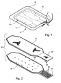
- an ankle splint product according to a preferred embodiment of the invention is illustrated broadly at reference numeral 10.
- a sealed, moisture-impervious foil and plastic laminated pouch or container 11 is fabricated of a aluminum foil laminate having an outer tear resistant layer, a central aluminum foil layer and an inner heat sealable plastic layer.
- Container 11 is opened with scissors or a knife, and an ankle splint 12 according to an embodiment of the invention is removed.
- Ankle splint 12 is formed from first and second separate splint segments 13 and 14, as is shown in Figure 2. Either of the splint segments 13 or 14 may be formed to the lateral or medial aspect of the ankle and lower leg. This interchangeability reduces manufacturing expense, inventory expense and simplifies application and replacement on the ankle after removal.
- each individual splint segment 13 and 14 may be placed in a separate container 11. This would allow, for example, replacement of one of the splint segments 13 or 14 while continuing to use the previously molded splint segment.
- Ankle splint segment 13 includes a multilayer substrate 16 formed of, for example, six layers of woven fiberglass fabric 16A-F overlaid in registration with each other to form a laminated structure.
- the fiberglass fabric layers 16A-F of the substrate 16 are impregnated or coated with a moisture-curable resin such as polyisocyanate as described in full in the present applicant's U.S. Pat. No. 4,770,299.
- This reactive system remains stable when maintained in substantially moisture-free conditions, such as in the moisture-impervious pouch 11, but hardens upon exposure to sufficient moisture to form a rigid, self-supporting structure.
- a typical formulation of the reactive system is set forth in the following table: Typical Formulation: Isonate ⁇ 143L or Mondur ⁇ CD or polyisocyanate 50.0% Rubinate ⁇ XI168 Pluracol ⁇ P1010 polyol 46.6% DC-200 Silicone defoaming agent 0.30% Benzoyl Chloride stabilizer 0.10% Thancat ⁇ DM-70 catalyst 3.0% 100%
- the polyisocyanate resin remains in a viscous, liquid unhardened state so long as the resin is not exposed to moisture. This permits the fiberglass layers 16A-F to remain flexible and moldable so long as the resin is not exposed to moisture, and for a relatively short period of time after exposure to moisture.
- the curing time can be controlled to some extent by the quantity and temperature of the water to which the resin is exposed. For example, exposure to water by dipping will result in quite rapid curing, while merely allowing the resin to be exposed to air will cause long curing times proportional to the amount of moisture in the air to which it is exposed.
- Resin coated or impregnated fiberglass layers 16A-F are covered with a foam protective pad 19, which may be a single thickness or a laminated structure.
- a foam protective pad 19 which may be a single thickness or a laminated structure.
- One preferred embodiment is a 0.48cm (3/16 inch) 2.72kg (six pound) EVA (ethylene vinyl acetate) pad.
- Another embodiment may be a 0.96cm (3/8 inch) laminated pad of a 0.32cm (1/8 inch) outer EVA pad and a 0.64cm (1/4 inch) outer polyethylene/polyurethane, combination open and closed cell foam.
- Spaced-apart ventilation holes 19A permit rapid penetration of water to the substrate 16 during wetting and curing, and permit improved air flow and cooling while being worn by the patient.
- the pad 19 covers and provides cushioning between the skin and the rigid substrate 16.
- the pad 19 is flexible enough to bend easily with the other components of the ankle splint segment 13 during fitting and curing.
- the pad 19 extends the entire length of the ankle splint segment 13.
- the pad 19 and the substrate 16 are approximately the same thickness on the order of about 4-6 mm.
- a fabric outer cover 20 such as a woven polyester fabric, covers the side of the substrate 16 opposite the side covered by the foam pad 19.
- the fabric cover is sewn with, for example, an overedge or serging seam 21 directly to the edges of the foam pad 19 enclosing the substrate 16.
- a patch 22 of male or female hook-and-loop material is sewn onto one end of the splint segment 13 defined as the bottom or heel end. As is shown in Figure 3, loops 23 on one face of the patch 22 are positioned on the same side of the splint segment 13 as the pad 19.
- the structure and shape of the splint segment 14 is essentially identical to that of the splint segment 13, this being noted throughout this application by reference numerals in prime notation.
- the only difference in splint segments 13 and 14 is a patch 24 of hook-and-loop material complementary to patch 22 is sewn onto one end of the splint segment 14.
- the hooks 25 on one side of the patch 24 are positioned on the same side of the splint segment 14 as the fabric cover 20'.
- the loops 23 face upwardly and the hooks 25 face downwardly, thereby allowing attachment of the two splint segments 13 and 14 together to collectively form the splint 12.
- the patches 22 and 24 when attached form a heel stirrup 27 which provides some padding and protection to the heel while stabilizing the lower portion of the splint 12.
- FIGs 4-11 preparation and application of the ankle splint 12 is illustrated.
- the ankle splint segments 13 and 14 have just been removed from the protective container 11 and the splint segment 13 is dipped in water to activate the moisture-curable resin described above. Immediately thereafter the splint segment 14 is likewise dipped in water.
- the wetted and still flexible ankle splint segments 13 and 14 are attached together by marrying the hook-and-loop patches 22 and 24 to form the heel stirrup 27 and the splint 12.
- the splint 12 is immediately placed on the foot by positioning the heel of the patient directly onto the heel stirrup 27.
- the splint segments 13 and 14 are each symmetrical along opposite sides of their longitudinal axis, so there is no defined forward or rearward side edge.
- the splint segments 13 and 14 of the splint 12 are then flexed upwardly along the lateral and medial aspects of the lower leg, as indicated by arrows 17 and 18 in Figure 6, so that the splint segments 13 and 14 are positioned as shown. See also Figures 7 and 8.
- ankle splint 12 is usable on either the right or left foot.
- the ankle splint 12 is held in place so that as the curing takes place the exact conformation of the ankle and leg is transferred to the ankle splint 12.
- the ankle splint 12 will harden within a matter of minutes, and will permanently retain the conformation in which it was held during curing. The fit is close and exact. With no voids to fill or accommodate as the patient moves about, complete and even protection to the body is provided.
- the pressure exerted by the splint 12 is very evenly spread over the maximum practical surface area, thereby reducing the possibility of chafing, rubbing or blistering at points of uneven pressure.
- heel stirrup 27 remains flexible after the splint segments 13 and 14 cure and harden. Removal and replacement of the splint 12 is facilitated since the custom-formed splint segments 13 and 14 easily fold away from the ankle, using the heel stirrup 27 as a hinge.
- a properly applied ankle splint 12 splints the medial and lateral aspects of the ankle and foot with minimal coverage of the front or rear of the foot or leg.
- eversion and inversion of the foot is prevented while permitting substantially unrestricted dorsiflexion and planoflexion necessary for normal walking and therapeutic exercise, and an enhanced ability to place the foot into a normal shoe.
- a relatively soft shoe such as an athletic shoe will accommodate the ankle splint 12 easily, it being necessary only to loosen the laces to permit added width to the shoe.
- the ankle splint 12 may be held in place during curing by a wrapping, such as a conventional elastic medical bandage 30.
- a wrapping such as a conventional elastic medical bandage 30.
- Such a bandage may also be worn during treatment as a way of maintaining a close fit of the ankle splint 12 against the foot and leg. This has been found to reduce edema in the front of the foot during the early stages of recovery, when pressure applied by the splint 12 to the sides of the ankle might otherwise force fluid to the front of the foot.
- a sock 35 may also be used to hold the ankle splint 12 in place during hardening, as is shown in Figure 10.
- Straps such as elastic straps or straps with hook and loop fasteners such as straps 40 and 41 may be used to hold the ankle splint 12 in place during treatment, as is shown in Figure 11. These straps preferably may be separate elements, like straps 40 and 41, or may be sewn onto the ankle splint 12 during manufacture.
- the heel stirrup 27 remains flexible, so some form of support is required to hold the splint 12 in supporting position against the ankle.
- the relative thinness and compactness of the splint 12 permits a wide variety of supports, including even a high-topped shoe or boot.
- each ankle splint segment 13 or 14 has an overall length of 30 cm, an overall width of 9 cm at a point one-half of the distance between the upper and lower ends and taper to a width of 5 cm at each end.
- the heel stirrup is preferably 5 cm wide and each of the hook-and-loop patches 22 and 24 are 7 cm long.
- each ankle splint segment 13 or 14 has an overall length of 35 cm, an overall width of 10 cm at a point one-half of the distance between the upper and lower ends and taper to a width of 5 cm at each end.
- the heel stirrup is preferably 5 cm wide and each of the hook-and-loop patches 22 and 24 are 7 cm long.
- the ends of the splint segments 13 and 14 may be rounded rather than tapered as shown in the drawings and described herein.
- other forms of cushion padding such as air bladders, gel-filled bladders or other types of foam or matrix products may be used.
- the approximate thickness of the body of the ankle splint 12 in both sizes is 8 mm, and of the hook-and-loop patches 22 and 24--2 mm.
- an ankle splint 100 further includes one or two separately attached foam cushion inserts 110 positioned, respectively, to reside adjacent one or both of the medial and lateral ankle bones "B" of the patient to further protect and cushion the ankle when the splint 100 is being used.
- the medial ankle bone "B” is shown in Figure 12.
- the ankle splint 100 is formed of splint segments 111 and 112 constructed as described above with reference to splint segments 13 and 14.
- the reference herein to medial and lateral "ankle bones" means the lower prominences of the tibia and fibula, respectively, also known as the "malleoluses.”
- the cushion insert 110 has an inside major surface 110A which overlies the protective pad 116 of the splint segment 112 and includes a pressure-sensitive adhesive coating 118.
- the molded segment 112 is folded away from the ankle and the insert 110 placed in an area of the pad 116 residing adjacent the ankle bone "B" of the patient when the splint 100 is being used.
- Light application of pressure to an outside major surface 110B of the insert 110 activates the pressure-sensitive adhesive coating 118 which holds the insert 110 in place as the splint segment 112 is returned to its in-use position against the ankle.
- the adhesive coating 118 allows convenient removal and repositioning of the insert 110 for custom placement to suit the individual patient, and replacement of the insert 110 when worn.
- the outside major surface 110B of the insert 110 is adapted to reside against the skin of the patient.
- the cushion insert 110 is generally U-shaped with an open central area defined by a base 121 and opposing integrally-formed extensions 122 and 123.
- the term "U-shaped” is defined broadly herein to include, for example, structure which is generally V-shaped or horseshoe-shaped.
- the cushion insert 110 is formed of flexible, 0.64cm (1 ⁇ 4-inch) thick polycushion foam with an overall height of 8.33cm (3.28 inches) and an overall width of 6.45cm (2.54 inches).
- One cushion insert 110 is preferably used per splint segment 111 and 112 for each of the medial and lateral ankle bones of the patient.
- Strap 140 has opposing major sides 140A and 140B. Side 140B is covered with loops 141 which cooperate with hooks 144 which cover one side of an end tab 145.
- a buckle 147 is secured to the end of the strap 140 opposite the end tab 145 and permits the strap 140 to be formed into a closed loop by passing the end tab 145 through the buckle 147, folding the strap 140 onto itself and engaging the hooks 144 with the loops 141 at the desired position.
- two straps 140 are preferably used to hold the splint segments 13, 14 ( Figures 1-11) and the splint segments 111 and 112 ( Figures 12-14) against the lateral and medial aspects of the lower leg.
- Straps 140 provide significant advantages over the use of long elastic bandages. Such elastic bandages are sometimes more suitable for severe injuries and during the initial phases of healing when complete or almost complete immobilization of the injured limb is required.
- the elastic bandages such as the elastic bandage shown 30 shown in 9 cover substantially the entire length of the splint segments 13, 14 or 111, 112 and therefore significantly restricts movement of the foot and leg.
- the bandage 30 also requires some time and practice to apply properly. There is a danger of overtightening, since such products have elongations of 100 percent or more.
- Non-elastic straps of the type furnished with prior art devices do not conform to the generally conical shape of the lower leg. Thus, either the top or the bottom of the strap is too loose or too tight. Non-elastic straps merely hold the splint in place, but provide no additional benefits to the patient. As the patient walks and the leg changes size and shape, the strap is not permitted to also change to accommodate these changes.
- strap 140 includes up to about 25 percent longitudinal elasticity, although the strap 140 will ordinarily be placed on the leg with no more than about 5-10 percent elongation.
- the top and bottom edges of the strap 140 may elongate independently of each other to precisely conform to the shape and circumference of the leg at the point of contact.
- This elasticity permits increased movement by the patient.
- the calf and other muscles of the lower leg and foot contract and relax, varying somewhat the circumference and shape of the lower leg.
- the usual three-position step causes the calf muscle to alternately relax ( Figure 17) and flex ( Figure 19) as the foot and leg move through its range of motion.
- the elasticity of the strap 140 permits the calf muscle to stretch the strap 140 slightly and progressively ( Figures 18 and 19) during each step. When the muscle is relaxed, the strap 140 contracts against the muscle. This repetitive pumping action helps milk out edema and increase blood flow. This not only speeds healing, but may reduce the possibility of phlebitis which can sometimes result from prolonged immobilization of or unyielding pressure on the limb.
- the straps 140 may be very quickly secured around the leg, removed and adjusted as needed.
Description
| Typical Formulation: | |
| Isonate□ 143L or | |
| Mondur□ CD or polyisocyanate | 50.0% |
| Rubinate □ XI168 | |
| Pluracol□ P1010 polyol | 46.6% |
| DC-200 Silicone defoaming agent | 0.30% |
| Benzoyl Chloride stabilizer | 0.10% |
| Thancat□ DM-70 catalyst | 3.0% |
| 100% |
Claims (27)
- An ankle splint product including an ankle splint (12) for being custom-formed to the shape of an ankle while flexible and upon hardening providing a rigid, supporting custom fit, said ankle splint product comprising:(a) an outer container (11) formed of moisture-impervious material;(b) first and second flexible ankle splints (13,14) positioned in the container (11) in substantially moisture-free conditions and sealed therein against entry of moisture until use, each of the first and second ankle splints (13,14)comprising(i) an elongate substrate (16);(ii) a reactive system impregnated into or coated onto the substrate(16), the system remaining stable when maintained in substantially moisture-free conditions and hardening upon exposure to moisture to form a rigid, self-supporting structure;(iii) an elongate, flexible protective pad (19) positioned on one side of the substrate (16) along its length to provide a cushioning barrier between the substrate (16) and the skin of a patient when the ankle splint (12) is in use;(iv) an elongate outer cover (20) covering the substrate on a side opposite the protective pad (19); and(v) said substrate (16), protective pad (20) and outer cover (20) being connected together into a unitary structure for being molded while flexible to an aspect of the lower leg; and(d) at least one elasticized strap member (140) for being extended around the first and second splints (13,14) and fastened to itself in tensioned condition for holding the first and second splints (13,14) in conforming position on the lower leg and ankle and providing controlled compressive support to the lower leg and ankle, characterised in that the ankle splint being formed from first and second separate splints, the splints being attached at one end by a single first attachment means secured to one end of said first splint (13), and a single second attachment means secured to one end of said second splint (14) and cooperating with said first attachment means for releasably attaching the first and second splints (13,14) together into an ankle splint (12) and for forming a heel stirrup (27) for stabilizing the first and second splints (13,14) on the lateral and medial aspects of the ankle.
- An ankle splint product according to claim 1, wherein said strap member (140) comprises:(a) an elongate strap body having as least some longitudinally-extending elastic yarns for permitting compressive stretch along the length of the strap (140) in conformance with the contour of the leg; and(b) fastening means for securing the strap around the lower leg.
- An ankle splint product according to claim 2, wherein said fastening means comprises:(i) a buckle (147) attached to one end of the strap member; and(ii) an end tab (145) secured to an opposing end of the strap member for being received through the buckle and attached to the strap member.
- An ankle splint product according to claim 3, wherein said strap member includes:(a) one or the other of hook or loop material on a major surface thereof; and(b) complementary hook or loop material carried by the end tab (145) for being attached to the hook or loop material on the strap member.
- An ankle splint product according to claim 4, wherein said strap member includes a cushion insert having a first major surface overlying said protective pad (19) and an opposing second major surface adapted for residing adjacent an anklebone of the patient, said cushion insert cooperating with said protective pad (19) to further protect and cushion the ankle of the patient when the ankle splint (12) is in use.
- An ankle splint product according to claim 1, 2, 3, 4 or 5, wherein said splint (12) product includes first and second like elasticized strap members (140) for being extended around the first and second splints (13,14) and fastened in a tensioned condition at two vertically spaced-apart positions on the lower leg for holding the first and second splints in conforming position on the lower leg and ankle and providing controlled compressive support to the lower leg and ankle.
- An ankle splint product according to claim 1, 2, 3, 4 or 5, wherein said strap (140) has a maximum elongation of approximately 25 percent.
- An ankle splint product according to any preceding claim including a flexible cushion insert (110) having a first major surface overlying said protective pad (19) and an opposing second major surface adapted for residing adjacent an ankle bone of the patient, said cushion insert (110) cooperating with said protective pad (19) to further protect and cushion the ankle of the patient when the ankle splint (12) is in use.
- An ankle splint product according to claim 8, wherein said cushion insert (110) is generally U-shaped to define an open central area for accommodating the ankle bone of the patient.
- An ankle splint product according to claim 8, and comprising attachment means on the first major surface of said cushion insert (110) for attaching said cushion insert to said ankle splints.
- An ankle splint product according to claim 10, wherein said attachment means comprises a pressure-sensitive adhesive (118).
- An ankle splint product according to claim 8, wherein said cushion insert (110) is formed of between 0.64 and 1.28cm thick foam.
- An ankle splint product according to claim 1, wherein said first and second attachment means comprise first and second mating patches of hook-and-loop material.
- An ankle splint product according to claim 13, wherein said first and second patches of hook and loop material are attached to one end of respective first and second splints (13,14) with sewing stitches.
- An ankle splint product according to claim 1, wherein the container (11) is fabricated of an aluminum foil laminate having an outer tear resistant layer, a central aluminum foil layer and an inner heat sealable plastic layer.
- An ankle splint product according to claim 1, wherein the substrate (16) comprises a plurality of knitted, woven or non-woven fabric layers.
- An ankle splint product according to claim 1, wherein the protective pad (19) comprises a foam material.
- An ankle splint product according to claim 17, wherein the foam material is chosen from the group consisting of open or closed cell EVA or polyurethane.
- An ankle splint product according to claim 1, wherein the elongate outer cover (20) is formed of a synthetic, hydrophobic fabric.
- An ankle splint product according to claim 19, wherein the fabric of the outer cover (20) is chosen from the group consisting of woven, knitted or non-woven fabric.
- An ankle splint product according to claim 1, wherein the reactive system comprises a blended polyisocyanate, polyol, catalyst and stabilizer.
- An ankle splint product according to claim 1, wherein said protective pad (19), substrate (16) and outer cover (20) are sandwiched together in overlying layers and joined together around their respective peripheral edges by sewing stitches to form a unitary structure.
- An ankle splint product according to claim 1, wherein the protective pad (19) and the substrate (16) are of substantially equal thickness.
- An ankle splint product according to claim 1, wherein the protective pad (19) is between 4 and 6 mm thick and the substrate is between 4 and 6 mm thick.
- An ankle splint product according to claim 1, wherein the first and second splints (13,14) have the same peripheral shape.
- An ankle splint product according to claim 1, wherein the first and second splints (13,14) have same peripheral shape and are symmetrical along a centerline extending the length of the substrate.
- An ankle splint product according to claim 1, wherein the first and second splints (13,14) have same peripheral shape, are symmetrical along a centerline extending the length of the substrate (10), and have tapered upper and lower ends.
Applications Claiming Priority (3)
| Application Number | Priority Date | Filing Date | Title |
|---|---|---|---|
| US09/143,755 US6022331A (en) | 1998-03-27 | 1998-08-31 | Custom-fitted ankle splint |
| US143755 | 1998-08-31 | ||
| PCT/US1999/007323 WO2000012034A1 (en) | 1998-08-31 | 1999-04-02 | Custom-fitted ankle splint product |
Publications (3)
| Publication Number | Publication Date |
|---|---|
| EP1109518A1 EP1109518A1 (en) | 2001-06-27 |
| EP1109518A4 EP1109518A4 (en) | 2002-03-06 |
| EP1109518B1 true EP1109518B1 (en) | 2005-10-12 |
Family
ID=22505454
Family Applications (1)
| Application Number | Title | Priority Date | Filing Date |
|---|---|---|---|
| EP99914335A Expired - Lifetime EP1109518B1 (en) | 1998-08-31 | 1999-04-02 | Custom-fitted ankle splint product |
Country Status (7)
| Country | Link |
|---|---|
| US (1) | US6022331A (en) |
| EP (1) | EP1109518B1 (en) |
| JP (1) | JP3577629B2 (en) |
| AU (1) | AU3220699A (en) |
| CA (1) | CA2342812C (en) |
| DE (1) | DE69927697T2 (en) |
| WO (1) | WO2000012034A1 (en) |
Families Citing this family (19)
| Publication number | Priority date | Publication date | Assignee | Title |
|---|---|---|---|---|
| US6131195A (en) * | 1999-07-29 | 2000-10-17 | Parker Athletic Products, Llc | Custom-fitted batter's lower leg protector |
| US6128777A (en) * | 1999-07-29 | 2000-10-10 | Parker Athletic Products, Llc | Custom-fitted batter's forearm protector |
| US6134720A (en) * | 1999-07-29 | 2000-10-24 | Parker Athletic Products, Llc | Shin guard with enhanced tibial protection |
| US7008390B2 (en) * | 2000-04-03 | 2006-03-07 | Evoluzione S.R.L. | Perforating vein massage device |
| US6767332B1 (en) | 2000-05-31 | 2004-07-27 | Chris C. Pardue | Active ankle support |
| US6361516B1 (en) | 2000-11-09 | 2002-03-26 | Christopher Ronald Hamel | Posterior ankle splint shaper |
| US6464658B1 (en) * | 2000-12-07 | 2002-10-15 | Bsn Medical Inc. | Custom-formable knee immobilizer product, knee immobilizer and method |
| GB0031460D0 (en) * | 2000-12-22 | 2001-02-07 | Moore Timothy I | Lock and load whole ankle brace |
| GB2389795B (en) * | 2002-06-22 | 2005-04-20 | Atkinson Jennifer Anne | Ankle braces |
| US7465284B2 (en) * | 2003-02-11 | 2008-12-16 | Aaron Huppert | Ankle support |
| US7465281B2 (en) * | 2003-04-18 | 2008-12-16 | Ossur, Hf | Versatile hardenable cast or support |
| US7250034B2 (en) * | 2003-05-13 | 2007-07-31 | Alessandro Barberio | Venting devices for surgical casts and other orthopedic devices |
| US20070049855A1 (en) * | 2005-08-25 | 2007-03-01 | Restorative Care Of America Incorporated | Ankle stirrup brace |
| US7758529B2 (en) * | 2006-08-09 | 2010-07-20 | Medefficiency, Inc. | Systems and methods for improved off-weighting |
| EP2150214B1 (en) * | 2007-05-21 | 2015-11-11 | Ossur Hf | Orthopedic device |
| WO2017171126A1 (en) * | 2016-03-31 | 2017-10-05 | 주식회사 이엠텍 | Method for manufacturing splint using thermoplastic resin raw fabric and splint manufactured thereby |
| US11793254B2 (en) | 2020-06-04 | 2023-10-24 | Wilson Sporting Goods Co. | Sports glove |
| USD995796S1 (en) * | 2020-10-16 | 2023-08-15 | Darleen Yllas | Medical bandage |
| US11771153B1 (en) | 2022-04-20 | 2023-10-03 | Wilson Sporting Goods Co. | Batter's hand guard |
Family Cites Families (20)
| Publication number | Priority date | Publication date | Assignee | Title |
|---|---|---|---|---|
| US4287920A (en) * | 1977-10-17 | 1981-09-08 | Johnson Jr Glenn W | Self-sealing valve |
| US4502479A (en) * | 1979-09-04 | 1985-03-05 | Minnesota Mining And Manufacturing Company | Water-activated casting material |
| US4570622A (en) * | 1981-12-31 | 1986-02-18 | Bayer Aktiengesellschaft | Constructional material |
| US4442833A (en) * | 1981-03-27 | 1984-04-17 | Cutter Laboratories, Inc. | Casting or splinting package |
| US4495942A (en) * | 1981-12-04 | 1985-01-29 | Palumbo Pasquale M | Dynamic ankle brace |
| US4899738A (en) * | 1987-01-06 | 1990-02-13 | Parker A Bruce | Roll form medical bandaging product |
| US4841957A (en) * | 1988-03-28 | 1989-06-27 | Wooten Beven P | Brace for treating and relieving posterior heel pain |
| US4865023A (en) * | 1988-04-20 | 1989-09-12 | Craythorne Colin M | Ankle support apparatus |
| US5088478A (en) * | 1988-05-10 | 1992-02-18 | Royce Medical Company | Gel and air cushion ankle brace |
| US4996979A (en) * | 1989-10-13 | 1991-03-05 | Royce Medical Company | Soft-goods type, formable orthopaedic cast |
| US5217431A (en) * | 1992-02-20 | 1993-06-08 | Smith & Nephew Donjoy, Inc. | Orthopedic ankle brace |
| US5199941A (en) * | 1992-03-13 | 1993-04-06 | Makinen Robbie W | Contoured ankle brace and stabilizer |
| US5456658A (en) * | 1992-03-30 | 1995-10-10 | Parker Medical Associates | Custom-fitting body part protector with cure-retarding storage system, method of constructing a body part protector, and method of custom-fitting a body part protector |
| US5676641A (en) * | 1993-04-15 | 1997-10-14 | Arensdorf; Stephen C. | Stabilized ankle support |
| US5389065A (en) * | 1993-06-15 | 1995-02-14 | Aircast, Inc. | Ankle brace with ATF compression |
| US5499820A (en) * | 1995-06-07 | 1996-03-19 | Albertsson; Peter S. | Golf swing training device and method |
| US5634854A (en) * | 1995-06-07 | 1997-06-03 | Albertsson; Peter S. | Golf swing training device and method |
| US5544663A (en) * | 1995-07-20 | 1996-08-13 | Parker Medical Associates | Front-to-back and side-to-side custom-molded protective device |
| US5637077A (en) * | 1995-10-30 | 1997-06-10 | Smith & Nephew Casting, Inc. | Custom-molded ankle brace |
| DE19638683A1 (en) * | 1996-09-20 | 1998-04-02 | Biedermann Motech Gmbh | Ankle orthosis |
-
1998
- 1998-08-31 US US09/143,755 patent/US6022331A/en not_active Expired - Lifetime
-
1999
- 1999-04-02 AU AU32206/99A patent/AU3220699A/en not_active Abandoned
- 1999-04-02 WO PCT/US1999/007323 patent/WO2000012034A1/en active IP Right Grant
- 1999-04-02 DE DE69927697T patent/DE69927697T2/en not_active Expired - Fee Related
- 1999-04-02 JP JP2000567158A patent/JP3577629B2/en not_active Expired - Lifetime
- 1999-04-02 EP EP99914335A patent/EP1109518B1/en not_active Expired - Lifetime
- 1999-04-02 CA CA002342812A patent/CA2342812C/en not_active Expired - Lifetime
Also Published As
| Publication number | Publication date |
|---|---|
| DE69927697T2 (en) | 2006-07-13 |
| CA2342812A1 (en) | 2000-03-09 |
| JP2002523180A (en) | 2002-07-30 |
| JP3577629B2 (en) | 2004-10-13 |
| CA2342812C (en) | 2004-08-17 |
| EP1109518A1 (en) | 2001-06-27 |
| AU3220699A (en) | 2000-03-21 |
| WO2000012034A8 (en) | 2000-04-27 |
| EP1109518A4 (en) | 2002-03-06 |
| US6022331A (en) | 2000-02-08 |
| WO2000012034A1 (en) | 2000-03-09 |
| DE69927697D1 (en) | 2006-02-23 |
Similar Documents
| Publication | Publication Date | Title |
|---|---|---|
| EP1109518B1 (en) | Custom-fitted ankle splint product | |
| US5637077A (en) | Custom-molded ankle brace | |
| US6712780B2 (en) | Custom-formable knee immobilizer product, knee immobilizer and method | |
| US5957871A (en) | Custom-fitted ankle splint product | |
| US6056713A (en) | Moldable custom-fitted ankle brace | |
| US7128725B2 (en) | Ankle brace | |
| US5944678A (en) | Ankle brace | |
| EP3034051B1 (en) | Circumferential walker | |
| US5980474A (en) | Custom-fitted ankle splint | |
| US5868693A (en) | Custom-fitted athletic ankle brace | |
| US8672865B2 (en) | Weight-bearing lower extremity brace | |
| US9820870B2 (en) | Weight-bearing lower extremity brace | |
| US5843010A (en) | Heel and ankle appliance | |
| EP2381902B1 (en) | Weight-bearing lower extremity brace | |
| WO1997036507A1 (en) | Orthopedic cast walker boot | |
| EP3856093A1 (en) | Ankle support | |
| CA2438790C (en) | Custom-fitted ankle splint product | |
| WO2021161277A1 (en) | System for limb injuries to allow early ambulation with stabilization | |
| AU2005203587A1 (en) | Orthotic device | |
| WO2020115769A1 (en) | An adjustable limb stabilization device | |
| AU4934193A (en) | An ankle brace |
Legal Events
| Date | Code | Title | Description |
|---|---|---|---|
| PUAI | Public reference made under article 153(3) epc to a published international application that has entered the european phase |
Free format text: ORIGINAL CODE: 0009012 |
|
| 17P | Request for examination filed |
Effective date: 20010302 |
|
| AK | Designated contracting states |
Kind code of ref document: A1 Designated state(s): DE FR GB IT |
|
| A4 | Supplementary search report drawn up and despatched |
Effective date: 20020117 |
|
| AK | Designated contracting states |
Kind code of ref document: A4 Designated state(s): DE FR GB IT |
|
| RIC1 | Information provided on ipc code assigned before grant |
Free format text: 7A 61F 3/00 A, 7A 61F 13/00 B, 7A 61F 5/01 B |
|
| 17Q | First examination report despatched |
Effective date: 20030520 |
|
| RAP1 | Party data changed (applicant data changed or rights of an application transferred) |
Owner name: BSN MEDICAL, INC. |
|
| GRAP | Despatch of communication of intention to grant a patent |
Free format text: ORIGINAL CODE: EPIDOSNIGR1 |
|
| GRAS | Grant fee paid |
Free format text: ORIGINAL CODE: EPIDOSNIGR3 |
|
| GRAA | (expected) grant |
Free format text: ORIGINAL CODE: 0009210 |
|
| AK | Designated contracting states |
Kind code of ref document: B1 Designated state(s): DE FR GB IT |
|
| REG | Reference to a national code |
Ref country code: GB Ref legal event code: FG4D |
|
| REF | Corresponds to: |
Ref document number: 69927697 Country of ref document: DE Date of ref document: 20060223 Kind code of ref document: P |
|
| ET | Fr: translation filed | ||
| PLBE | No opposition filed within time limit |
Free format text: ORIGINAL CODE: 0009261 |
|
| STAA | Information on the status of an ep patent application or granted ep patent |
Free format text: STATUS: NO OPPOSITION FILED WITHIN TIME LIMIT |
|
| 26N | No opposition filed |
Effective date: 20060713 |
|
| PGFP | Annual fee paid to national office [announced via postgrant information from national office to epo] |
Ref country code: DE Payment date: 20080425 Year of fee payment: 10 |
|
| PGFP | Annual fee paid to national office [announced via postgrant information from national office to epo] |
Ref country code: IT Payment date: 20080423 Year of fee payment: 10 |
|
| PGFP | Annual fee paid to national office [announced via postgrant information from national office to epo] |
Ref country code: FR Payment date: 20080414 Year of fee payment: 10 |
|
| PGFP | Annual fee paid to national office [announced via postgrant information from national office to epo] |
Ref country code: GB Payment date: 20080402 Year of fee payment: 10 |
|
| GBPC | Gb: european patent ceased through non-payment of renewal fee |
Effective date: 20090402 |
|
| REG | Reference to a national code |
Ref country code: FR Ref legal event code: ST Effective date: 20091231 |
|
| PG25 | Lapsed in a contracting state [announced via postgrant information from national office to epo] |
Ref country code: DE Free format text: LAPSE BECAUSE OF NON-PAYMENT OF DUE FEES Effective date: 20091103 |
|
| PG25 | Lapsed in a contracting state [announced via postgrant information from national office to epo] |
Ref country code: GB Free format text: LAPSE BECAUSE OF NON-PAYMENT OF DUE FEES Effective date: 20090402 Ref country code: FR Free format text: LAPSE BECAUSE OF NON-PAYMENT OF DUE FEES Effective date: 20091222 |
|
| PG25 | Lapsed in a contracting state [announced via postgrant information from national office to epo] |
Ref country code: IT Free format text: LAPSE BECAUSE OF NON-PAYMENT OF DUE FEES Effective date: 20090402 |