EP1109455B1 - Carrier indentification device - Google Patents
Carrier indentification device Download PDFInfo
- Publication number
- EP1109455B1 EP1109455B1 EP99945752A EP99945752A EP1109455B1 EP 1109455 B1 EP1109455 B1 EP 1109455B1 EP 99945752 A EP99945752 A EP 99945752A EP 99945752 A EP99945752 A EP 99945752A EP 1109455 B1 EP1109455 B1 EP 1109455B1
- Authority
- EP
- European Patent Office
- Prior art keywords
- housing
- transponder
- meat
- hook
- hole
- Prior art date
- Legal status (The legal status is an assumption and is not a legal conclusion. Google has not performed a legal analysis and makes no representation as to the accuracy of the status listed.)
- Expired - Lifetime
Links
Images


Classifications
-
- A—HUMAN NECESSITIES
- A22—BUTCHERING; MEAT TREATMENT; PROCESSING POULTRY OR FISH
- A22B—SLAUGHTERING
- A22B7/00—Slaughterhouse arrangements
- A22B7/001—Conveying arrangements
- A22B7/007—Means containing information relative to the carcass that can be attached to or are embedded in the conveying means
-
- A—HUMAN NECESSITIES
- A22—BUTCHERING; MEAT TREATMENT; PROCESSING POULTRY OR FISH
- A22B—SLAUGHTERING
- A22B7/00—Slaughterhouse arrangements
- A22B7/001—Conveying arrangements
- A22B7/002—Devices for hanging animal carcasses while being conveyed or stored, e.g. gambrels, hooks
Definitions
- the invention relates to identification systems and to a system to assist in tracking meat from production to packaging.
- it relates to a carrier identification device.
- Transponders are particularly well-suited to the electronic identification of animals since they are passive devices that are read actively, they require no internal power supply and are able to hold sufficient information to uniquely identify a single animal amongst several million animals.
- the transponder is removed from the animal before or during slaughtering. This means that continued tracking of the animal can be lost. As mentioned above, it is desirable to continue to track the fate of an animal until processing is complete and the produce has reached the end user. To achieve this aim it is necessary to continue to uniquely identify the animal, or components of the animal, during downstream processing.
- Document US-A-5,781,112 discloses a transmitter for unique identification of a transport device such as a hanger, which is mounted within a housing.
- a carrier identification device for identifying a carrier in a food processing environment, said device comprising a housing and a transponder mounted in the housing, said transponder containing an identifying code, wherein said housing is firmly mounted to said carrier in a hole formed in an arm of said carrier.
- the housing is pressed into the hole with an interference fit.
- the transponder contains a unique identifying code.
- the housing is preferably formed from food grade material and is heat and acid resistant.
- the housing is suitably formed from plastics material and in preference, ultra high molecular weight polyethylene material.
- the inventor has found that a cylindrical housing is most suitable.
- the transponder is mounted in a cylindrical cavity drilled perpendicular to an axis of the housing.
- a silicon potting mix can be used to hold the transponder in position.
- the transponder is positioned such that an antenna of the transponder is aligned with an outer face of the housing.
- the invention resides in a carrier identification device for identifying a meat hook in a meat processing place, said meat hook being of the form having a body shaped at an upper end to have an 'H' section holding a bush; wherein the housing is firmly mounted to the body in a hole formed in the meat hook and a transponder is mounted in the housing, said transponder containing an identifying code.
- the hole is preferably formed in an arm of the 'H' section of the meat hook.
- the housing is press fitted in the hole with interference fit.
- the housing is preferably mounted wholly within the hole so that no part of the housing extends beyond an edge of the body.
- the invention resides in a carrier identification device for identifying a meat hook in a meat processing plant, said meat hook being of the form having a body curved at an upper end to define a space between a return portion and a main portion with a wheel mounted between the return and main portion; wherein the housing is firmly mounted to the body and a transponder is mounted in the housing, said transponder containing an identifying code.
- the housing is mounted in the space utilizing one or more pins inserted through aligned holes in the return portion and the main portion so as to clamp the housing against the upper end of the body of the meat hook.
- the housing is preferably mounted wholly within the space so that no part of the housing extends beyond an edge of the body.
- the housing is mounted in a hole formed in the meat hook.
- the hole is preferably formed in the main portion and the housing is preferably mounted wholly within the hole so that no part of the housing extends beyond an edge of the body.
- the transponder is removably mounted in the housing and the housing is removably mounted to the body.
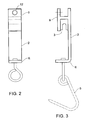
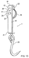
- FIG 1 a first embodiment of a carrier for an animal carcass.
- the carrier is in the form of a meat hook 1, consisting of a body 2 having a bush 3 located at an upper end 4 and a hook 5 hanging from a lower end 6.
- the body 2 is formed at the upper end 4 to form an 'H' section 7 that supports the bush 3.
- the cross 8 of the 'H' section 7 supports the top of the bush 3 which is wedged between the arms 9, 10 of the 'H' section.
- An electronic identification device such as a transponder 11 in a housing 12, is located in a hole 13 formed in the arm 9 of the 'H' section 7.
- the housing 12 is pressed into the hole 13 with an interference fit such that the housing 12 is securely held within the hole 13. However, if the meat hook 1 becomes damaged, the housing 12 can be pressed from the hole 13 for recovery of the transponder 11 and housing 12.
- the preferred position of the hole 13 in the arm 9 is shown most clearly in FIG 2 and FIG 3.
- the transponder and housing are easily fitted and removed.
- the transponder is protected from damage due to the containment of the housing 12 within the boundaries of the meat hook 1.
- the meat hook 1 is made from metal and may therefore interfere with the signal obtained from a transponder.
- the transponder signal can be read from up to one metre away providing that the transponder is located a suitable distance from the body of the meat hook.
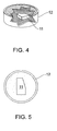
- the inventor has found that a housing with 26mm diameter can house a 12mm long transponder without significant interference to the operation of the transponder.
- the positioning of the transponder 11 within the housing 12 is shown most clearly in FIG 4 and FIG 5.
- the embodiment consists of a 26mm diameter housing holding a flat transponder approximately 12mm x 6mm by 4mm thick. There is a minimum spacing between the transponder and the housing of at least 4mm. It will be appreciated that the specific minimum distance will depend upon the size and nature of the transponder, the nature of the housing, the power of the reading antenna, the distance to the reading antenna, and the metal of the meat hook.
- the figures show one preferred embodiment of transponder and location. Other transponders may also be suitable with appropriate positioning.
- the housing 12 In order to survive in this environment the housing 12 must be strongly held in the hole 13. It is also important that the transponder is suitably mounted in the housing.
- One preferred arrangement is to encase the transponder within a suitable resin. To ensure that the transponder is correctly positioned within the housing, an initial layer of resin is poured into the housing. The transponder is then carefully positioned in the center of the housing and a covering layer of resin is poured.
- a suitable resin is an epoxy resin able to withstand temperatures up to 140°C. The resin must also be resistant to phosphoric acid that is used to clean the meat hooks.
- the structure of the housing and the manner of securing the housing on the meat hook facilitates maintenance when required. If the transponder fails the housing can be quickly removed and replaced. If the meat hook becomes unserviceable the housing can be pressed from the hole and fitted to another hook.
- the bar code on the packaging will provide the starting point for a recorded history of the animal from birth to consumption.
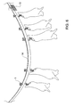
- the use of the meat hook identification device is depicted in FIG 6.
- a plurality of meat hooks are suspended on a track 14
- the identification of the animal is recorded, suitably by reading the transponder resident in the animals rumen or ear tag.
- the carcass is hung on a meat hook, or a number of meat hooks if the carcass is divided.
- the identity of the meat hook(s) is recorded against the animal identification.
- the meat hook identification is determined by an antenna, such as 15.
- the processing data such as weight, quality, wastage etc is recorded at each processing station.
- a typical processing plant may have six or more antennas for tracking the carcass.
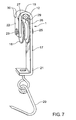
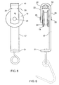
- FIG 7 a second embodiment of a carrier for an animal carcass.
- the carrier is in the form of a meat hook 1, consisting of a body 17 having a wheel 18 located at an upper end 19 and a hook 20 hanging from a lower end 21.
- the body 17 is turned at the upper end 19 to form a return portion 22 that supports the outer end 23 of the wheel axle 24.
- the near end 25 of the wheel axle 24 is supported by a main portion 26 of the body 17.
- a space 27 is formed above the wheel 18 between the return portion 22 and the main portion 26 of the body 17.
- An electronic identification device such as a transponder (not visible) in a housing 12, is located in the space 27.
- the housing 28 is held in place by roll pins 29 that extend from the return portion 22 to the main portion 26 of the body 17.
- roll pins 29 spaced towards the ends of the transponder housing 28.
- Roll pins are formed from rolled metal and provide a high degree of resilient compressibility. When forced into a hole the roll pin will try to expand and thereby be firmly held within the hole.
- holes 30 are formed in the return portion 22 and the main portion 26 of the body 17.
- the holes are aligned so that a single roll pin can be pushed through a pair of holes from one side.
- the pins may be suitably biased to apply moderate pressure against the housing 12. In this manner the housing 12 is held firmly against the upper end 19 of the body 17.
- the roll pins 29 form a closed electric circuit with the upper end 19 of the body 17. This circuit can interfere with the operation of the transponder.
- the roll pins 29 must be spaced beyond the ends of the transponder as it is positioned within the housing located in the space at the upper end of the body.
- pins 31 that are not continuous, as shown in FIG 10. If pins 31 are used they can be positioned anywhere along the housing. Such a solution is not preferred since the housing 12 is not held as strongly against the upper end 19.
- pins can be used instead of roll pins.
- a non-conducting bush could be placed within the holes around the pins.
- Other methods of holding the housing in the space could also be used (for example, glue, vertical pins, single sided pins, screws), however, the inventors have found that roll pins provide reliable holding of the housing 12 in the space 27.
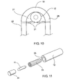
- FIG. 11 One preferred arrangement for holding a transponder in the housing is shown in FIG 11.
- a transponder 11 is fitted within a shock absorbing sheath 33, which is snugly located within the housing 12.
- a removable plug 34 closes the aperture 35 through which the transponder 32 and sheath 33 are loaded.
- a typical embodiment consists of a 23 mm long transponder having a diameter of 3 mm located within a housing 45 mm long with a diameter of 23 mm.
- the aperture has a diameter of 7 mm to receive the transponder when surrounded by the sheath.
- Different size transponders and housings will also be suitable.
- the housing is suitably made from a hard material, such as barium sulphate bound in polyropylene or a ceramic, that is able to withstand impacts expected in a meat processing facility.
- the material must also be food grade, heat resistant and acid resistant.
- the structure of the housing and the manner of securing the housing on the meat hook facilitates maintenance when required. If the transponder fails it can be quickly removed and replaced by virtue of the removable plug 34. If the meat hook becomes unserviceable the housing can be removed, by roll pins, and fitted to another hook. If the housing is damaged the transponder is recoverable for continued use.
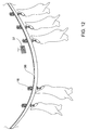
- FIG. 12 The use of the second embodiment of the invention is depicted in FIG 12.
- a plurality of meat hooks are suspended on a track 36.
- the meat hook identification is determined by an antenna, such as 37.
- the facility of FIG 12 is similar to that described with respect to FIG 6.
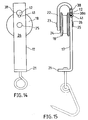
- FIG. 13 A third embodiment of the invention is shown in FIG's 13,14 and 15.
- the meat hook 1 has the same design as the meat hook shown in FIG 7.
- the meat hook 1 consists of a body 17 having a wheel 18 located at an upper end 19 and a hook 20 hanging from a lower end 21.
- the body 17 is turned at the upper end 19 to form a return portion 22 that supports the outer end 23 of the wheel axle 24.
- the near end 25 of the wheel axle 24 is supported by a main portion 26 of the body 17.
- a hole 38 is formed in the main portion 26 of the body 17.
- the hole 38 has a lip 38a on the inside, as seen most clearly in FIG 15.
- An electronic identification device such as a transponder 11 in a housing 12, is located in the hole 38.
- the housing 12 fits into the hole 38 with an interference fit and is secured by hammer screw 41.
- the hammer screw 41 is hammered into a hole drilled in the main portion 26 adjacent the hole 38.
- the rounded head prevents snagging but allows for removal of the hammer screw. Removal is effected by using a cold chisel and hammer to unscrew the hammer screw.
- the housing 12 is held firmly within the hole 38 but can be removed if replacement of the transponder 11 is required.
- the housing 12 is fitted in a hole in the main portion 26. It will be appreciated that it could be fitted into a similar hole in the return portion 22.
- the rotating wheel 18 can generate a magnetic field that interferes with the operation of the transponder 11.
- This problem can be overcome by careful placement of the transponder 39 within the housing 12.
- the transponder 11 is positioned in a cylindrical cavity 42 drilled into the side of the cylindrical housing 12.
- the cavity 42 is generally perpendicular to the axis 43 of the housing 12.
- the transponder 11 is placed in the cavity 42 so that the antenna face 44 is facing outwards.
- the housing 12 is then placed in the hole 38 so that the transponder is positioned generally transversely with respect to the body 17 of the meat hook 16.
- a silicon potting mix is injected into the hole.
- a plug 45 clamps against the transponder and seals the cavity.
- a channel 46 in the plug 45 allows excess silicon to escape.
- the plug 45 will extend beyond the housing, as seen in FIG 17. Once the silicon potting mix has cured the excess plug can be cut away.
- the housing 40 is then fitted to the body 17 to achieve the alignment shown in side view in FIG 18.
- a suitable material for the housing 12 is a machinable ultra high molecular weight polyethylene.
- the inventor has used a product known as Tivar® 1000 available from Menasha Corporation through Cadillac Plastics in Australia. This material is heat and acid resistant, of food grade and has good mechanical properties.
- the structure of the housing and the manner of securing the housing on the meat hook facilitates maintenance when required. If the transponder fails it can be quickly removed and replaced by virtue of the removable plug 45. If the meat hook becomes unserviceable the housing can be removed, by removing the hammer screw, and fitting to another hook. If the housing is damaged the transponder is recoverable for continued use.
- read/write transponders are used on the carrier.
- the animal identification is read from the animal as it is being slaughtered and is written into the transponder on the meat hook (or hooks) that carry the carcass. At the end of processing the identification can be written into the bar code on the packaging.
- This system provides direct identification of the history of a consumer meat product.
Abstract
Description
wherein the housing is firmly mounted to the body in a hole formed in the meat hook and a transponder is mounted in the housing, said transponder containing an identifying code.
wherein the housing is firmly mounted to the body and a transponder is mounted in the housing, said transponder containing an identifying code.
- FIG 1
- shows a first embodiment of meat hook with a transponder in place;
- FIG 2
- is a front view of the meat hook of FIG 1 showing the transponder;
- FIG 3
- is a side view of the meat hook of FIG 1 showing the location of the transponder in hidden detail;
- FIG 4
- shows a cutaway perspective view of the housing of FIG 1;
- FIG 5
- shows a plan view of the location of the transponder in the housing of FIG 4;
- FIG 6
- exemplifies the application of the first embodiment of the invention to a meat processing facility;
- FIG 7
- shows a second embodiment of a meat hook with a transponder in place;
- FIG 8
- is a front view of the meat hook of FIG 7 showing the transponder housing in hidden detail;
- FIG 9
- is a side view of the meat hook of FIG 7 showing one means for holding the transponder in position;
- FIG 10
- shows an alternate means to FIG 9 for holding the transponder in place;
- FIG 11
- shows in detail the fitting of the transponder within the housing; and
- FIG 12
- exemplifies the application of the second embodiment of the invention to a meat processing facility;
- FIG 13
- shows a third embodiment of a meat hook with a transponder in place;
- FIG 14
- is a front view of the meat hook of FIG 13;
- FIG 15
- is a cut away side view of the meat hook of FIG 13 showing the means for holding the transponder in position;
- FIG 16
- shows in detail the fitting of the transponder within the housing and the housing in the hole;
- FIG 17
- shows the fitting of the transponder in the housing; and
- FIG 18
- shows a cross-section side view of the transponder in the housing in the body.
Claims (13)
- A carrier identification device for identifying a carrier (1) in a food processing environment, said device comprising a housing (12) and a transponder (11) mounted in the housing (12), said transponder (11) containing an identifying code, characterised in that said housing (12) is firmly mounted to said carrier (1) in a hole (13; 38) formed in an arm of said carrier (1).
- A device according to claim 1, characterised in that the housing (12) is pressed into the hole (13; 38) with an interference fit.
- A device according to claim 1, characterised in that the housing (12) is formed from plastics material.
- A device according to claim 1, characterised in that the housing (12) is formed from ultra high molecular weight polyethylene material.
- A device according to claim 1, characterised in that the transponder (11) is removably mounted in the housing (12) and the housing (12) is removably mounted in the hole (13,38).
- A device according to claim 1, characterised in that the transponder (11) is mounted in a cavity (42) formed in the housing (12) such that an antenna of the transponder (11) is aligned with an outer face of the housing (12).
- A device according to claim 1, characterised in that the carrier is a meat hook (1) in a meat processing plant, said meat hook (1) being of the form having a body (2) shaped at an upper end to have an 'H' section (7) holding a bush (3), the hole (13) being formed in the meat hook (1).
- A device according to claim 7, characterised in that the hole (13) is formed in an arm (9) of the 'H' section (7) of the meat hook.
- A device according to claim 1, characterised in that the housing (12) is mounted wholly within the hole (13) so that no part of the housing (12) extends beyond an edge of the body (2).
- A carrier identification device for identifying a meat hook (1) in a meat processing plant, said device comprising a housing (12) and a transponder mounted in the housing (11), said transponder (11) containing an identifying code, said meat hook (1) being of the form having a body (17) curved at an upper end (19) to define a space (27) between a return portion (22) and a main portion (26) with a wheel (18) mounted between the return portion (22) and the main portion (26) characterised in that the housing (12) is firmly mounted in the space (27) utilising one or more pins (29; 31) inserted through aligned holes (30) in the return portion (22) and the main portion (26) so as to clamp the housing (12) against the upper end (19) of the body (17) of the meat hook (1).
- A device according to claim 10, characterised in that the housing (12) is mounted wholly within the space (27) so that no part of the housing (12) extends beyond an edge of the body (17).
- A device according to claim 10, characterised in that the transponder (11) is removably mounted in the housing (12) and the housing (12) is removably mounted to the body (17).
- A device according to claim 10, characterised in that the transponder (11) is mounted in a cavity (42) formed in the housing (12) such that an antenna of the transponder (11) is aligned with an outer face of the housing (12).
Applications Claiming Priority (7)
| Application Number | Priority Date | Filing Date | Title |
|---|---|---|---|
| AUPP564998 | 1998-09-02 | ||
| AUPP5649A AUPP564998A0 (en) | 1998-09-02 | 1998-09-02 | Carrier identification device |
| AUPP622198 | 1998-09-29 | ||
| AUPP6221A AUPP622198A0 (en) | 1998-09-29 | 1998-09-29 | Carrier identification device |
| AUPP809999 | 1999-01-11 | ||
| AUPP8099A AUPP809999A0 (en) | 1999-01-11 | 1999-01-11 | Carrier identification device |
| PCT/AU1999/000718 WO2000013515A1 (en) | 1998-09-02 | 1999-09-02 | Carrier indentification device |
Publications (3)
| Publication Number | Publication Date |
|---|---|
| EP1109455A1 EP1109455A1 (en) | 2001-06-27 |
| EP1109455A4 EP1109455A4 (en) | 2002-07-03 |
| EP1109455B1 true EP1109455B1 (en) | 2005-08-31 |
Family
ID=27158095
Family Applications (1)
| Application Number | Title | Priority Date | Filing Date |
|---|---|---|---|
| EP99945752A Expired - Lifetime EP1109455B1 (en) | 1998-09-02 | 1999-09-02 | Carrier indentification device |
Country Status (9)
| Country | Link |
|---|---|
| EP (1) | EP1109455B1 (en) |
| JP (1) | JP2002524363A (en) |
| AT (1) | ATE303068T1 (en) |
| BR (1) | BR9913420A (en) |
| CA (1) | CA2342907C (en) |
| DE (1) | DE69927036T2 (en) |
| ES (1) | ES2249026T3 (en) |
| NZ (1) | NZ510278A (en) |
| WO (1) | WO2000013515A1 (en) |
Families Citing this family (9)
| Publication number | Priority date | Publication date | Assignee | Title |
|---|---|---|---|---|
| US6724309B2 (en) | 2000-11-03 | 2004-04-20 | Excel Corporation | Method and apparatus for tracking carcasses |
| US7766730B2 (en) | 2000-11-03 | 2010-08-03 | Cargill, Incorporated | Carcass tracking |
| US7400256B2 (en) | 2000-11-03 | 2008-07-15 | Cargill, Incorporated | Chill cooler storage and selection system |
| AUPR524801A0 (en) * | 2001-05-25 | 2001-06-21 | Aleis Trakit Pty Ltd | Livestock processing antenna |
| NL1024150C2 (en) | 2003-08-22 | 2005-02-23 | Stork Pmt | Device and method for processing slaughtered animals and / or parts thereof provided with a transport system. |
| US7411500B2 (en) | 2005-09-14 | 2008-08-12 | 3M Innovative Properties Company | Methods of monitoring items or material from manufacturing processes |
| DE202010017361U1 (en) * | 2010-12-08 | 2011-12-01 | Tönnies Holding GmbH & Co. KG | A system for providing data and / or information regarding meat products via a communications network |
| JP7189552B2 (en) * | 2019-09-27 | 2022-12-14 | 株式会社南日本情報処理センター | meat inspection system |
| KR102525690B1 (en) * | 2022-05-23 | 2023-04-25 | 주식회사 백우돈 | Meat transfer rail system |
Family Cites Families (4)
| Publication number | Priority date | Publication date | Assignee | Title |
|---|---|---|---|---|
| US4597495A (en) | 1985-04-25 | 1986-07-01 | Knosby Austin T | Livestock identification system |
| DE4244150C2 (en) * | 1992-12-24 | 1995-04-06 | Duerkopp Adler Ag | Load carrier for a suspended conveyor system |
| AU670907B3 (en) | 1995-11-03 | 1996-08-01 | Alfa Laval Agri Ab | Attachable transponder housing |
| US5781112A (en) * | 1997-02-03 | 1998-07-14 | Shymko; Wayne W. | Electronic tagging device for identifying transported products |
-
1999
- 1999-09-02 CA CA002342907A patent/CA2342907C/en not_active Expired - Fee Related
- 1999-09-02 BR BR9913420-9A patent/BR9913420A/en not_active IP Right Cessation
- 1999-09-02 NZ NZ510278A patent/NZ510278A/en not_active IP Right Cessation
- 1999-09-02 DE DE69927036T patent/DE69927036T2/en not_active Expired - Lifetime
- 1999-09-02 JP JP2000568332A patent/JP2002524363A/en active Pending
- 1999-09-02 EP EP99945752A patent/EP1109455B1/en not_active Expired - Lifetime
- 1999-09-02 ES ES99945752T patent/ES2249026T3/en not_active Expired - Lifetime
- 1999-09-02 AT AT99945752T patent/ATE303068T1/en not_active IP Right Cessation
- 1999-09-02 WO PCT/AU1999/000718 patent/WO2000013515A1/en active IP Right Grant
Also Published As
| Publication number | Publication date |
|---|---|
| ES2249026T3 (en) | 2006-03-16 |
| EP1109455A1 (en) | 2001-06-27 |
| ATE303068T1 (en) | 2005-09-15 |
| WO2000013515A1 (en) | 2000-03-16 |
| DE69927036T2 (en) | 2006-06-08 |
| EP1109455A4 (en) | 2002-07-03 |
| JP2002524363A (en) | 2002-08-06 |
| CA2342907C (en) | 2004-03-23 |
| BR9913420A (en) | 2001-10-16 |
| DE69927036D1 (en) | 2005-10-06 |
| NZ510278A (en) | 2002-03-01 |
| CA2342907A1 (en) | 2000-03-16 |
Similar Documents
| Publication | Publication Date | Title |
|---|---|---|
| US6452497B1 (en) | Carrier identification device | |
| US6545604B1 (en) | Methods for electronic tracking of units originating from a common source, and assemblies comprising transponders attached to meat spikes | |
| EP1109455B1 (en) | Carrier indentification device | |
| US5697384A (en) | Internal identification apparatus for animals | |
| IL282728B2 (en) | Method and apparatus for tracking one or more plants and/or plant based products and/or tracking the sale of products derived from the same, utilizing rfid technology | |
| WO2002047485A8 (en) | Method and apparatus for tracking carcasses | |
| WO2006091765A2 (en) | Dual frequency identification device | |
| IE900119A1 (en) | Animal ear tags | |
| CA2736825A1 (en) | Passive rfid chip reader antenna and embedded rfid chips | |
| DK1228482T3 (en) | Container tracking system and recyclable container with a transponder | |
| AU747238B2 (en) | Carrier indentification device | |
| US6494305B1 (en) | Carcass-tracking apparatus housing carcass-tracking apparatus and carcass-tracking methods | |
| DE60001653D1 (en) | LABEL FOR ELECTRONIC ITEM IDENTIFICATION, METHOD FOR CODING AN IDENTITY CODE ON SUCH LABEL, AND DEVICE FOR IDENTIFYING THE SAME | |
| US9558683B2 (en) | Identification tag adapted to be clipped to a shaft | |
| CN104915694A (en) | RFID (radio frequency identification) based live-pig breeding information acquisition system | |
| KR20190017404A (en) | Ear tag and method making thereof | |
| CN217546989U (en) | Intelligent ear tag for livestock raising | |
| NZ260514A (en) | Ingestable capsule for ruminant animal; capsule contains transponder and removable plug | |
| PL345312A1 (en) | Method for determining the origin of and/or identifying animals or biological material | |
| Brits | More than just an ID number... | |
| UA67351A (en) | System of identifying cattle in the ukraine | |
| Slader et al. | Electronic live animal and carcass identification systems | |
| CA2471781A1 (en) | A grommet rfid asset tracking system | |
| NO985284D0 (en) | Method of marking metallic objects by encapsulating identifiable individual identification, as well as coded and readable tag for the purpose |
Legal Events
| Date | Code | Title | Description |
|---|---|---|---|
| PUAI | Public reference made under article 153(3) epc to a published international application that has entered the european phase |
Free format text: ORIGINAL CODE: 0009012 |
|
| 17P | Request for examination filed |
Effective date: 20010402 |
|
| AK | Designated contracting states |
Kind code of ref document: A1 Designated state(s): AT BE CH CY DE DK ES FI FR GB GR IE IT LI LU MC NL PT SE |
|
| AX | Request for extension of the european patent |
Free format text: AL;LT;LV;MK;RO;SI |
|
| A4 | Supplementary search report drawn up and despatched |
Effective date: 20020522 |
|
| AK | Designated contracting states |
Kind code of ref document: A4 Designated state(s): AT BE CH CY DE DK ES FI FR GB GR IE IT LI LU MC NL PT SE |
|
| RIC1 | Information provided on ipc code assigned before grant |
Free format text: 7A 22C 15/00 A, 7G 01V 15/00 B, 7A 22B 5/00 B, 7A 22B 7/00 B, 7B 61B 10/02 B |
|
| 17Q | First examination report despatched |
Effective date: 20030226 |
|
| GRAP | Despatch of communication of intention to grant a patent |
Free format text: ORIGINAL CODE: EPIDOSNIGR1 |
|
| GRAS | Grant fee paid |
Free format text: ORIGINAL CODE: EPIDOSNIGR3 |
|
| GRAA | (expected) grant |
Free format text: ORIGINAL CODE: 0009210 |
|
| AK | Designated contracting states |
Kind code of ref document: B1 Designated state(s): AT BE CH CY DE DK ES FI FR GB GR IE IT LI LU MC NL PT SE |
|
| PG25 | Lapsed in a contracting state [announced via postgrant information from national office to epo] |
Ref country code: NL Free format text: LAPSE BECAUSE OF FAILURE TO SUBMIT A TRANSLATION OF THE DESCRIPTION OR TO PAY THE FEE WITHIN THE PRESCRIBED TIME-LIMIT Effective date: 20050831 Ref country code: LI Free format text: LAPSE BECAUSE OF FAILURE TO SUBMIT A TRANSLATION OF THE DESCRIPTION OR TO PAY THE FEE WITHIN THE PRESCRIBED TIME-LIMIT Effective date: 20050831 Ref country code: FI Free format text: LAPSE BECAUSE OF FAILURE TO SUBMIT A TRANSLATION OF THE DESCRIPTION OR TO PAY THE FEE WITHIN THE PRESCRIBED TIME-LIMIT Effective date: 20050831 Ref country code: CH Free format text: LAPSE BECAUSE OF FAILURE TO SUBMIT A TRANSLATION OF THE DESCRIPTION OR TO PAY THE FEE WITHIN THE PRESCRIBED TIME-LIMIT Effective date: 20050831 Ref country code: BE Free format text: LAPSE BECAUSE OF FAILURE TO SUBMIT A TRANSLATION OF THE DESCRIPTION OR TO PAY THE FEE WITHIN THE PRESCRIBED TIME-LIMIT Effective date: 20050831 Ref country code: AT Free format text: LAPSE BECAUSE OF FAILURE TO SUBMIT A TRANSLATION OF THE DESCRIPTION OR TO PAY THE FEE WITHIN THE PRESCRIBED TIME-LIMIT Effective date: 20050831 |
|
| REG | Reference to a national code |
Ref country code: GB Ref legal event code: FG4D Ref country code: CH Ref legal event code: EP |
|
| PG25 | Lapsed in a contracting state [announced via postgrant information from national office to epo] |
Ref country code: CY Free format text: LAPSE BECAUSE OF FAILURE TO SUBMIT A TRANSLATION OF THE DESCRIPTION OR TO PAY THE FEE WITHIN THE PRESCRIBED TIME-LIMIT Effective date: 20050902 |
|
| REG | Reference to a national code |
Ref country code: IE Ref legal event code: FG4D |
|
| PG25 | Lapsed in a contracting state [announced via postgrant information from national office to epo] |
Ref country code: MC Free format text: LAPSE BECAUSE OF NON-PAYMENT OF DUE FEES Effective date: 20050930 |
|
| REF | Corresponds to: |
Ref document number: 69927036 Country of ref document: DE Date of ref document: 20051006 Kind code of ref document: P |
|
| PG25 | Lapsed in a contracting state [announced via postgrant information from national office to epo] |
Ref country code: LU Free format text: LAPSE BECAUSE OF NON-PAYMENT OF DUE FEES Effective date: 20051031 |
|
| PG25 | Lapsed in a contracting state [announced via postgrant information from national office to epo] |
Ref country code: SE Free format text: LAPSE BECAUSE OF FAILURE TO SUBMIT A TRANSLATION OF THE DESCRIPTION OR TO PAY THE FEE WITHIN THE PRESCRIBED TIME-LIMIT Effective date: 20051130 Ref country code: GR Free format text: LAPSE BECAUSE OF FAILURE TO SUBMIT A TRANSLATION OF THE DESCRIPTION OR TO PAY THE FEE WITHIN THE PRESCRIBED TIME-LIMIT Effective date: 20051130 Ref country code: DK Free format text: LAPSE BECAUSE OF FAILURE TO SUBMIT A TRANSLATION OF THE DESCRIPTION OR TO PAY THE FEE WITHIN THE PRESCRIBED TIME-LIMIT Effective date: 20051130 |
|
| PG25 | Lapsed in a contracting state [announced via postgrant information from national office to epo] |
Ref country code: PT Free format text: LAPSE BECAUSE OF FAILURE TO SUBMIT A TRANSLATION OF THE DESCRIPTION OR TO PAY THE FEE WITHIN THE PRESCRIBED TIME-LIMIT Effective date: 20060222 |
|
| NLV1 | Nl: lapsed or annulled due to failure to fulfill the requirements of art. 29p and 29m of the patents act | ||
| REG | Reference to a national code |
Ref country code: CH Ref legal event code: PL |
|
| REG | Reference to a national code |
Ref country code: ES Ref legal event code: FG2A Ref document number: 2249026 Country of ref document: ES Kind code of ref document: T3 |
|
| ET | Fr: translation filed | ||
| PLBE | No opposition filed within time limit |
Free format text: ORIGINAL CODE: 0009261 |
|
| STAA | Information on the status of an ep patent application or granted ep patent |
Free format text: STATUS: NO OPPOSITION FILED WITHIN TIME LIMIT |
|
| 26N | No opposition filed |
Effective date: 20060601 |
|
| REG | Reference to a national code |
Ref country code: GB Ref legal event code: 732E |
|
| REG | Reference to a national code |
Ref country code: ES Ref legal event code: PC2A |
|
| REG | Reference to a national code |
Ref country code: FR Ref legal event code: TP Ref country code: FR Ref legal event code: CA |
|
| PG25 | Lapsed in a contracting state [announced via postgrant information from national office to epo] |
Ref country code: IT Free format text: LAPSE BECAUSE OF NON-PAYMENT OF DUE FEES Effective date: 20100902 |
|
| PGRI | Patent reinstated in contracting state [announced from national office to epo] |
Ref country code: IT Effective date: 20110616 |
|
| PGFP | Annual fee paid to national office [announced via postgrant information from national office to epo] |
Ref country code: DE Payment date: 20130920 Year of fee payment: 15 Ref country code: IE Payment date: 20130927 Year of fee payment: 15 |
|
| PGFP | Annual fee paid to national office [announced via postgrant information from national office to epo] |
Ref country code: GB Payment date: 20130925 Year of fee payment: 15 |
|
| PGFP | Annual fee paid to national office [announced via postgrant information from national office to epo] |
Ref country code: IT Payment date: 20130920 Year of fee payment: 15 |
|
| PGFP | Annual fee paid to national office [announced via postgrant information from national office to epo] |
Ref country code: FR Payment date: 20130930 Year of fee payment: 15 |
|
| PGFP | Annual fee paid to national office [announced via postgrant information from national office to epo] |
Ref country code: ES Payment date: 20130925 Year of fee payment: 15 |
|
| REG | Reference to a national code |
Ref country code: DE Ref legal event code: R119 Ref document number: 69927036 Country of ref document: DE |
|
| GBPC | Gb: european patent ceased through non-payment of renewal fee |
Effective date: 20140902 |
|
| REG | Reference to a national code |
Ref country code: IE Ref legal event code: MM4A |
|
| REG | Reference to a national code |
Ref country code: FR Ref legal event code: ST Effective date: 20150529 |
|
| PG25 | Lapsed in a contracting state [announced via postgrant information from national office to epo] |
Ref country code: GB Free format text: LAPSE BECAUSE OF NON-PAYMENT OF DUE FEES Effective date: 20140902 Ref country code: DE Free format text: LAPSE BECAUSE OF NON-PAYMENT OF DUE FEES Effective date: 20150401 |
|
| PG25 | Lapsed in a contracting state [announced via postgrant information from national office to epo] |
Ref country code: IE Free format text: LAPSE BECAUSE OF NON-PAYMENT OF DUE FEES Effective date: 20140902 Ref country code: IT Free format text: LAPSE BECAUSE OF NON-PAYMENT OF DUE FEES Effective date: 20140902 Ref country code: FR Free format text: LAPSE BECAUSE OF NON-PAYMENT OF DUE FEES Effective date: 20140930 |
|
| REG | Reference to a national code |
Ref country code: ES Ref legal event code: FD2A Effective date: 20160205 |
|
| PG25 | Lapsed in a contracting state [announced via postgrant information from national office to epo] |
Ref country code: ES Free format text: LAPSE BECAUSE OF NON-PAYMENT OF DUE FEES Effective date: 20140903 |