EP1109356A2 - Collision-free multiple access reservation scheme for burst communications using a plurality of frequency tones - Google Patents
Collision-free multiple access reservation scheme for burst communications using a plurality of frequency tones Download PDFInfo
- Publication number
- EP1109356A2 EP1109356A2 EP00311028A EP00311028A EP1109356A2 EP 1109356 A2 EP1109356 A2 EP 1109356A2 EP 00311028 A EP00311028 A EP 00311028A EP 00311028 A EP00311028 A EP 00311028A EP 1109356 A2 EP1109356 A2 EP 1109356A2
- Authority
- EP
- European Patent Office
- Prior art keywords
- unique
- uplink
- remote units
- base station
- uplink request
- Prior art date
- Legal status (The legal status is an assumption and is not a legal conclusion. Google has not performed a legal analysis and makes no representation as to the accuracy of the status listed.)
- Granted
Links
Images


Classifications
-
- H—ELECTRICITY
- H04—ELECTRIC COMMUNICATION TECHNIQUE
- H04W—WIRELESS COMMUNICATION NETWORKS
- H04W28/00—Network traffic management; Network resource management
- H04W28/16—Central resource management; Negotiation of resources or communication parameters, e.g. negotiating bandwidth or QoS [Quality of Service]
- H04W28/26—Resource reservation
-
- H—ELECTRICITY
- H04—ELECTRIC COMMUNICATION TECHNIQUE
- H04L—TRANSMISSION OF DIGITAL INFORMATION, e.g. TELEGRAPHIC COMMUNICATION
- H04L5/00—Arrangements affording multiple use of the transmission path
- H04L5/003—Arrangements for allocating sub-channels of the transmission path
- H04L5/0053—Allocation of signaling, i.e. of overhead other than pilot signals
-
- H—ELECTRICITY
- H04—ELECTRIC COMMUNICATION TECHNIQUE
- H04L—TRANSMISSION OF DIGITAL INFORMATION, e.g. TELEGRAPHIC COMMUNICATION
- H04L5/00—Arrangements affording multiple use of the transmission path
- H04L5/0001—Arrangements for dividing the transmission path
- H04L5/0003—Two-dimensional division
- H04L5/0005—Time-frequency
- H04L5/0007—Time-frequency the frequencies being orthogonal, e.g. OFDM(A), DMT
-
- H—ELECTRICITY
- H04—ELECTRIC COMMUNICATION TECHNIQUE
- H04L—TRANSMISSION OF DIGITAL INFORMATION, e.g. TELEGRAPHIC COMMUNICATION
- H04L5/00—Arrangements affording multiple use of the transmission path
- H04L5/0001—Arrangements for dividing the transmission path
- H04L5/0014—Three-dimensional division
- H04L5/0016—Time-frequency-code
-
- H—ELECTRICITY
- H04—ELECTRIC COMMUNICATION TECHNIQUE
- H04W—WIRELESS COMMUNICATION NETWORKS
- H04W24/00—Supervisory, monitoring or testing arrangements
-
- H—ELECTRICITY
- H04—ELECTRIC COMMUNICATION TECHNIQUE
- H04W—WIRELESS COMMUNICATION NETWORKS
- H04W4/00—Services specially adapted for wireless communication networks; Facilities therefor
- H04W4/12—Messaging; Mailboxes; Announcements
-
- H—ELECTRICITY
- H04—ELECTRIC COMMUNICATION TECHNIQUE
- H04W—WIRELESS COMMUNICATION NETWORKS
- H04W74/00—Wireless channel access, e.g. scheduled or random access
Definitions
- This invention relates generally to communication systems and, more particularly, to a system and method for efficiently transmitting and receiving messages in a multiple access communications network without collisions.
- a channel defined as a bandwidth of frequency in a frequency division system or a time slot in a time division system, is considered a fixed communication resource.
- several remote units in the system must typically share the fixed resource. That is, the remote units must all use the same channel.
- the term multiple access refers to the sharing of a fixed communication resource.
- Multiple Access Control (MAC) protocols can be divided into two broad categories - fixed assignment and random access. Random access protocols can be further divided into pure random access and controlled random access.
- Fixed assignment MAC protocols are typically used when a continuous stream of data is to be transmitted. Examples of such data are digitized voice traffic, video transmission and facsimile transmission.
- the most common fixed assignment methods include Frequency Division Multiple Access (FDMA), in which sub-bands of frequency are specified; Time Division Multiple Access (TDMA), in which periodic time slots are specified; and Code Division Multiple Access (CDMA), in which a set of orthogonal spread spectrum codes are specified.
- FDMA Frequency Division Multiple Access
- TDMA Time Division Multiple Access
- CDMA Code Division Multiple Access
- Random access MAC protocols provide a more flexible and efficient way of managing channel access for communication of short data messages.
- Commonly used random access schemes include the pure ALOHA protocol, the slotted-ALOHA protocol, Carrier Sense Multiple Access with Collision Detection (CSMA/CD) and Data Sense Multiple Access with Collision Detection (DSMA/CD).
- Controlled random access methods include Reservation Aloha, Polling and Token passing schemes.
- the fundamental characteristic of random access MAC protocols that limits their achievable throughput is the high incidence of packet collisions under heavy loads of offered data message traffic. A collision is considered to have occurred when two or more users attempt to access the channel simultaneously. During a collision the channel resources are, in effect, wasted. The maximum achievable throughput for the slotted ALOHA protocol is only about 37% and that of DSMA/CD is about 50%. Controlled random access protocols exercise more control over the access method and as a result avoid some of the inefficiencies of the pure random access schemes.
- the prior art DSMA/CD system is loosely based on the DSMA/CD scheme by CDPD (cellular digital packet data).
- the DSMA/CD system consists of a base station and a number of remote units.
- the base station receives data messages from the remote units on one shared channel.
- the base station transmits information about the shared channel to the remote units on a different channel.
- the remote units can only listen on the channel on which the base transmits. They cannot listen to the channel on which they themselves transmit.
- the information transmitted by the base station consists of two bits of information.
- the Busy/Idle bit informs the remote units if the shared channel is in use by one of the remote units already.
- the Decode Status bit informs the remote unit if a data message, transmitted on the shared channel, has been successfully received by a base station.
- the process of accessing the channel by the remote units is known as arbitration.
- a remote unit looks at the Busy /Idle bit it receives from the base station. If the shared channel is busy, then the remote unit waits until the received Busy/Idle bit indicates that the shared channel is idle. Once the shared channel is idle, the remote unit can begin its transmission of the data message on the channel. It continues to sense the Busy/Idle bit after it has begun its transmission. If the remote unit is the only one that has accessed the channel, then the Busy/Idle bit will be set to busy after the duration of a round-trip delay between the base station and the remote unit. This round-trip delay includes the propagation time for the transmissions between the remote station and the base unit, as well as any processing of the data by the base station and the remote unit.
- the base station If the base station successfully receives the data message transmissions from the remote unit, then it indicates that the remote unit has successfully accessed the channel by setting the Busy/Idle flag to busy. The remote unit will see the busy indication after a round-trip delay and will continue data message transmission until it is done.
- the maximum amount of time the remote unit is allowed to transmit is usually fixed as a system design parameter.
- a second remote unit has a data message to transmit at the same time as the first remote unit, then it too will see that the channel is idle, and it too will begin to transmit its data message.
- the base station will receive a signal that consists of the superposition of the transmitted data messages from both remote units.
- the base station detects that more than one remote unit is transmitting simultaneously and in this case keeps the Busy/Idle bit at idle.
- Both remote units will see the idle indication after a round-trip delay.
- the fact that the channel has remained idle indicates to both units that they have not successfully accessed the channel and so they cease transmissions immediately. They both delay a random amount of time before attempting to access the channel again. This delay is known as a backoff.
- the remote units will continue to attempt to transmit their data messages until the data message is successfully transmitted or until the maximum number of allowable backoffs has been reached. If the maximum number of backoffs has been reached, then the data message is simply discarded.
- the uplink utilization does not change appreciably as the number of remote units is increased from 5 to 30, as shown in Table 1. However, the utilization is relatively low, at approximately 54%.
- Table 1 illustrates the uplink utilization vs. the number of active remote units in a heavily loaded system. Uplink Utilization vs. Number of active remote units Number of RUs Uplink Utilization % Discarded 5 54.1% .4% 10 54.6% 1.4% 15 54.2% 3.1% 20 53.4% 4.8%
- the uplink utilization does not present the total picture however.
- the number of discarded frames as a function of the number of remote units must also be examined. In Table 1 it can be seen that the number of discarded frames increases approximately linearly with the number of active RUs on the system. The only way to bring down the number of discards is by increasing the maximum allowable number of backoffs or by increasing the size of the backoffs. However, doing so decreases the latency and throughput for smaller numbers of remote units.
- the utilization with the DSMA/CD algorithm is at best ⁇ 55%. This means that 45% of the shared channel capacity is being lost.
- a remote unit After a remote unit has finished its data message transmissions, it must attempt once again to gain access to the shared channel.
- the duration of the access attempt is non-deterministic due to the possibility of collisions on the uplink.
- the DSMA/CD algorithm toggles between the arbitration period and channel-seized period for each remote unit that wants to access the uplink, which is an inefficient use of the shared channel.
- the number of frames discarded is a function of the number of active remote units on the system and the maximum number of backoffs. Increasing the maximum number of backoffs reduces the percentage of discarded frames. However, this can lead to an 'unfair' sharing of the uplink in the short term.
- the backoff period increases exponentially with the number of backoffs. While remote unit #1 is backing off multiple times, remote unit #2 may be grabbing the channel between backoffs, in effect blocking remote unit #1 from ever gaining access to the shared channel. Also, multiple backoffs by the MAC layer may lead to backoffs by the upper layers (e.g., FTP), which further exaggerates the unfair sharing of uplink resources.
- the upper layers e.g., FTP
- a method for receiving messages from a plurality of remote units without collisions comprises: assigning unique uplink request signals to a plurality of remote units, including a first unique uplink signal to a first remote unit and a second unique uplink request signal to a second remote unit; monitoring the unique uplink request signals; simultaneously receiving monitored unique uplink request signals, including the first and second unique uplink request signals; and in response to receiving the first and second unique uplink request signals, authorizing the transmission of uplink data messages from the first and second remote units.
- the presence of a remote unit's unique uplink request signal indicates that the remote unit has a data message for transmission uplink.
- the absence of the unique uplink request signal indicates that the remote unit has no data message for transmission uplink.
- the assignment of a unique uplink request signal includes assigning a frequency tone to each of the plurality of remote units. To insure that multiple tones can be received without mutual interference, the assigned frequency tones are separated to be orthogonal to one another with respect to frequency. Further, temporal orthogonality is also used, as remote units transmit their tone frequencies in different time slots.
- the method further comprises establishing an arbitration state, the establishment of the arbitration state including soliciting the unique uplink request signals from the first plurality of remote units and, in response to soliciting the unique uplink request signals, monitoring the unique uplink request signals for a response.
- the method further comprises: establishing a data transfer state including organizing a first sequence of remote unit uplink data message transmissions; sending instructions to the first and second remote units for transmitting uplink data messages in the first sequence; and receiving the uplink data messages from the first and second remote units in the first sequence.
- a communication system for receiving uplink data messages without collisions comprises a base station which establishes an arbitration state to request unique uplink request signals, and which monitors unique uplink request signals.
- a first remote transmits a first unique uplink request signal to the base station in response to receiving the request for unique uplink request signals, and a second remote unit transmits a second unique uplink signal to the base station in response to receiving the request for unique uplink request signals.
- the base station monitors unique uplink request signals received simultaneously from the first and second remote units.
- the base station In response to receiving the first and second unique uplink request signals, the base station establishes a data transfer state to receive the uplink data messages from the first and second remote units in a non-interfering sequence. Then, the first and second remote units transmit uplink data messages in response to the uplink instruction from the base station.
- the unique uplink request signal of the remote units includes an orthogonal frequency tone, or a unique time slot.
- the unique signal includes a time slot assignment in addition to the frequency tone, so that multiple remote units can use the same tone (at different times).
- the unique uplink request signal is an orthogonal spreading code, or a combination of spreading code with orthogonal elements of frequency and time.
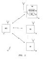
- Fig. 1 is a block diagram schematic illustrating the present invention communication system for receiving uplink data messages without collisions.
- Fig. 2 illustrates the orthogonal components of unique uplink request signals.
- Figs. 3a and 3b are a flowchart illustrating a method for receiving data messages at a base station without collisions.
- Fig. 4 is a flowchart illustrating a method to uplink data messages to a base station without collisions.
- Fig. 5 is a flowchart illustrating a method for communicating.
- Fig. 6 is a flowchart illustrating a method for receiving data messages in a collision-free sequence.
- Fig. 7 is a flowchart illustrating a method for a base station to identify a remote unit.
- Fig. 1 is a block diagram schematic illustrating the present invention communication system for receiving uplink data messages without collisions.
- the system 10 comprises a base station 12 having a port to transmit and receive messages.
- the base station 12 establishes an arbitration state to request unique uplink request signals and to monitor unique uplink request signals.
- a first remote unit 14 has a port in communication with the base station 12 to transmit and receive messages.
- the first remote unit 14 transmits a first unique uplink request signal to the base station in response to receiving the request for unique uplink request signals.
- the remote unit 14 sends a signal which is typically a single bit of information using on/off decoding.
- a second RU 16 has a port in communication with the base station 12 to transmit and receive messages.
- the second RU 16 transmits a second unique uplink request signal to the base station 12 in response to receiving the request for unique uplink request signals.
- the base station 12 monitors unique uplink request signals received simultaneously from the first and second RUs 14 and 16.
- the present invention system is also applicable to systems using hardwired cable or fiber channel connections, such as cable modems, Internet applications, and cable TV.
- This invention describes a method for multiple remote units (RUs) to efficiently utilize resources on a shared OFDM channel without collisions.
- a collision occurs when two or more RUs, for example RU 14 and 16, transmit on the same frequency at the same time.
- the base station 12 notifies the RUs 14 and 16 which state is in effect by transmitting a flag on the downlink.
- the base station 12 In response to receiving the first and second unique uplink request signals from the first and second RUs 14 and 16, the base station 12 establishes a data transfer state to receive the uplink data messages from the first and second remote units 14 and 16 in a non-interfering sequence. Then, the first and second RUs 14 and 16 transmit uplink data messages in response to the uplink instruction from the base station 12.
- the system 10 comprises a plurality of remote units, including the first 14, second 16, and nth 18 remote units, where n can be any number.
- Each of the plurality of RUs 14-18 communicate with the base station 12 to receive requests for unique uplink request signals.
- Each one of the plurality of remote units 14-18 transmits a unique uplink request signal which represents a data message ready for transmission uplink, and each one of the plurality of remote units 14-18 receives uplink data message instructions from the base station 12 in response to transmitting its unique uplink request signal.
- Each RU as represented by first RU 14, comprises a receiver 20 having an input to accept solicitations for uplink request signals transmitted by the base station 12.
- a transmitter 22 has an output to provide a first frequency tone, selected from a plurality of orthogonal frequency tones, which uniquely identifies the remote unit.
- the transmitter 20 sends the first frequency tone to the base station 12 in response to the solicitation of unique uplink request signals, to indicate the existence of a data message for transmission uplink.
- the uniqueness of the uplink request signals is established through the use of orthogonal signal components. Orthogonality can be achieved in the time (TDMA), frequency (FDMA), code (CDMA) and space (SDMA) domains.
- the unique uplink request signal of each of the plurality of remote units 14-18 includes a frequency tone selected from a plurality of unique frequency tones, where each of the plurality of frequency tones is orthogonal to the others.
- the RUs 14-18 are assigned an Arbitration Group ID Number (AGN) and a set of tones (normally a single tone) for use during the arbitration state.
- AGN Arbitration Group ID Number
- the base station 12 transmits an AGN on the downlink. If an RU has a data message to transmit, and its AGN matches that transmitted by the base 12, then it energizes the tones that have been assigned to it.
- the AGN and tone assignments are made in such a way that no two RUs in an arbitration group are assigned the same tone. Thus, multiple RUs 14-18 can arbitrate simultaneously.
- steps are taken to prevent "cresting", or an impulse spike occurring in the time domain which results from the plurality of frequency tones arriving at the base station 12 at the same time, and in phase. Therefore, unique uplink request signals from the first plurality of remote units 14-18 include the simultaneous, or near simultaneous, transmission of frequency tones from the plurality of frequency tones, having a random phase relationship to one another.
- the unique uplink request signals of each of the plurality of remote units 14-18 are orthogonal in time, as each RU 14-18 is assigned a unique time slot selected from a plurality of time slots.
- the unique uplink request signal incorporates elements of orthogonal time and frequency, so that the combination of a particular frequency tone and time slot forms a unique uplink request signal for each remote unit.
- the unique uplink request signal of each of the plurality of remote units 14-18 are orthogonal with respect to code, as each RU 14-18 is assigned a unique spreading code selected from a plurality of orthogonal spreading codes.
- the unique uplink request signal incorporates elements of orthogonal code and frequency, code and time, and code, frequency and time, so that the combination of elements forms a unique uplink request signal for each remote unit.
- Fig. 2 illustrates the orthogonal components of unique request signals.
- a plurality of frequencies, f 1 through f n are represented. Due to the spacing between the frequencies, they can be received in a wideband receiver without the effects of mutual interference. Thus, the signals of n RUs can be received simultaneously.
- the airlink can be sampled at distinct times, represented by times t 1 through t n . Further, the airlink can be sampled with respect to distinct spreading codes, represented by codes c 1 through c n .
- codes c 1 through c n In any one dimension, a total of n unique signals can be received. Combining two dimensions, time and frequency for example, a total of n x n uplink message signals can be received at the base state without interference. Combining three dimensions, a total of ( n x n x n ) unique uplink signals can be created.
- the assignment of the tones and timeslots for arbitration occurs when an RU makes an open request to the base station 12.
- the base station 12 through a management entity, assigns the tone and timeslot.
- the base station 12 performs all the centralized network functions.
- the base station 12 maintains a list of all active RU IDs and the tone/timeslot pairs that are assigned to them.
- the basic unit of transmission in the uplink is a Quad of 72 tones (18 tones x 2 frequency slots x 2 TDMA slots). Therefore, up to 72 RUs can be assigned a unique OFDM tone in a given Quad to arbitrate for the uplink data channel.
- AGN Arbitration Group Number
- the AGNs range from 0 to floor((numRUs-1)/72), where the "floor” is the integer part of a number, and numRUs is the number of RUs in the system.
- the base transmits the current AGN to all the RUs.
- the base 12 measures the power in the tones it receives from the RUs 14-18. If the base 12 detects energy above a threshold in some or all of the tones assigned to an RU, then it is determined that the RU corresponding to the assigned tone has data to transmit.
- the threshold can be determined by measuring the noise floor, and setting the threshold to a certain level above the noise floor. In the exemplary OFDM system, certain tone frequencies are reserved for this purpose. No RUs are permitted to transmit at the reserved frequencies.
- the smallest unit of time available is a time slot (375 microsecond) and the smallest unit of bandwidth is an OFDM tone.
- the goal in the arbitration state is for the RU to signal the base station that it desires to use the uplink data channel for the transmission of a data message, an OFDM tone in a single (375 microsecond) timeslot is sufficient to make the request.
- the minimum length of the arbitration state is determined by the amount of delay in the OFDM system. In the exemplary OFDM system, there is a 6 ms round-trip delay from when the RU sends a message to the base until it receives a reply to that message. Therefore, the minimum length of the arbitration state is 4 Quads (2 Quads are assigned to the uplink in every 3 ms TDMA frame). Note that an RU may transmit its arbitration tone more than once during an arbitration state, especially if the total number of AGNs is less than 4.
- a first RU may not get to transmit its arbitration tone during a given arbitration state if there are more AGNs than the minimum length of the arbitration state and a second RU has transmitted an arbitration tone earlier, thus preventing the AGN assigned to RUx from occurring during a given arbitration state.
- the AGN at the start of the next arbitration state continues from the AGN transmitted at the end of the previous arbitration sequence.
- the arbitration state remains in effect until the base 12 detects an RU, or RUs that have data messages to be transmitted.
- the base 12 determines which RUs have data messages to transmit from the energy measurements on the unique uplink request tones during the arbitration state. There are no predefined timeslots set aside for the arbitration state only, or for the transmission state only.
- the base 12 detects that some RUs have data messages to send, it switches to the data transfer state.
- the base station organizes a sequence of uplink data messages for transmission uplink.
- the base station 12 now sends in the downlink, either the RU ID or the Arbitration Group Number/Tone Number of the RU that is granted access to the uplink for the transmission of the data message, first RU 14 for example.
- Each of the first plurality of remote units 14-18 has a unique identifier, and the base station 12 uses the remote unit unique identifiers in transmissions to provide uplink data message sequence instructions to the remote units.
- the unique identification for each of the first plurality of remote units 14-18 can be a remote unit identification number.
- the uplink request signals of each RU are unique -- for example, a frequency/time slot combination -- the RU identification can be based on each remote unit having a unique uplink request signal, such as the unique combination of frequency tones and time slots.
- the base From the arbitration state, the base knows which RUs desire to transmit data messages uplink. The base can then allow uplink access to all of the RUs that requested it by sequentially stepping through the list of requesting RUs. The base can either send the RU ID of the RU that is next, or the Arbitration Slot Number/Tone number pair of that RU.
- Each of the RUs 14-18 receive the RU ID/AGN+Tone number, but only the RU with the matching identification, the first RU 14 for example, can now transmit a data message uplink.
- the first RU 14 transmits its data message to the base station 12. Once the base station 12 receives all the data from the first RU 14, it orders the next RU from which it received a unique uplink request signal during the arbitration period, the second RU 16 for example, to send its data message.
- An RU continues transmission of its data message until it either runs out of data to transmit, or it has transmitted the maximum amount of data allowed after a successful arbitration. With respect to the exemplary system, this may be any number of protocol data units (PDUs).
- the base 12 may allow an RU to transmit a variable number of PDUs, based on the number of RUs that indicated they have a data message to transmit during the arbitration period. For example, if only a single RU has data to send, then the base station 12 may allow it to send up to ten PDUs. If four or five RUs have data to send then the base station 12 may allow them to transmit only two or three PDUs each.
- the data transfer state remains in effect until all RUs have completed transmitting their data messages. Once all the data messages has been received, the base station 12 reverts back to the arbitration state.
- the base station 12 decodes each received PDU and transmits a decode status indicating whether the PDU has been successfully decoded. In this manner, the RUs can determine if their transmitted data message was successfully received and decoded.
- the remote units 14-18 repeat unique uplink request signals to retransmit unsuccessfully decoded uplink messages.
- the base station 12 monitors the unique uplink request signals requesting permission to retransmit uplink messages from remote units 14-18. In this manner, the remote units with unsuccessfully decoded uplink messages request another opportunity to uplink. Simultaneously, other remote units with new, or first-time, data messages for transmission uplink may also request service.
- the base station 12 receives unique uplink request signals from both groups of remote units and orders an uplink data message sequence which includes initial and repeat uplink data messages.
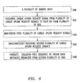
- Figs. 3a and 3b are a flowchart illustrating a method for receiving data messages at a base station without collisions. Although the process is depicted as a series of numbered steps for the purpose of clarity in the explanation, no order should be inferred from this numbering unless explicitly stated.
- Step 100 begins the method with a plurality of RUs.
- Step 102 assigns a plurality of unique uplink request signals to a plurality of remote units, including a first uplink request signal to a first remote unit and a second uplink request signal to a second remote unit.
- Step 104 monitors the plurality of unique uplink request signals.
- Step 106 simultaneously receives monitored unique uplink request signals, including the first and second unique uplink signals.
- Step 108a in response to receiving the first and second unique uplink request signals, determines that the first and second remote units have data messages to transmit uplink.
- Step 108b authorizes the transmission of uplink data messages from the first and second remote units to the base station.
- Step 110 is a product where the first and second remote units have reserved uplink data message transmission assignments without collisions.
- the method includes a plurality of frequency tones.
- the assignment of a unique uplink request signal in step 102 includes assigning a frequency tone from the plurality of frequency tones to each of the plurality of remote units.
- the assignment of frequency tones from the plurality of frequency tones to the plurality of remote units includes the plurality of frequency tones being orthogonal to one another.
- the simultaneous reception of the monitored unique uplink request signals in step 106 includes simultaneously receiving orthogonal frequency tones.
- the simultaneous reception of the monitored unique uplink request signals includes transmitting frequency tones from the plurality of frequency tones having a random phase relationship to one another.
- the assignment of frequency tones from the plurality of frequency tones to the plurality of remote units in step 102 includes assigning two tones from the plurality of frequency tones to each remote unit from the plurality of remote units. Two, or more, frequency tones are used when there is an increased probability of channel degradation.
- step 100 includes a plurality of time slots
- the assignment of a unique uplink request signal in step 102 includes assigning a time slot from the plurality of time slots to each of the plurality of remote units.
- the assignment of a unique uplink request signal includes the unique uplink request signals having both orthogonal frequencies and orthogonal time slots.
- step 106a simultaneously receives orthogonal frequency tones in a plurality of time slots.
- step 102 includes the unique uplink request signals being orthogonal spreading codes.
- the method further comprises a step, step 103, of establishing an arbitration state.
- the establishment of the arbitration state includes a sub-step, step 103a, of requesting unique uplink request signals from the plurality of remote units.
- the requesting of unique uplink request signals includes transmitting an arbitration state signal to the plurality of remote units.
- step 104 monitors the plurality of unique uplink request signals for a response.
- Step 107 establishes a data transfer state.
- Step 108 includes sending instructions to the first and second remote units for transmitting uplink data messages.
- the sending of instructions to the first and second remote unit for the transmission of uplink data messages includes transmitting a data transfer signal to the first and second remote units.
- Step 109 receives the uplink data messages from the first and second remote units.
- the present method establishes a reservation channel in step 103 and a data channel in Step 107, where the reservation and data channels are shared.
- step 106b organizes a first sequence of remote unit uplink data message transmissions.
- the sending of instructions for the transmission of uplink data messages in step 108 includes granting permission to transmit uplink data messages in the first sequence, and the reception of the uplink data messages in step 109 includes receiving uplink data messages in the first sequence.
- Step 109a decodes the data uplink messages.
- Step 109b sends decode status messages indicating whether the uplinked messages have been successfully decoded.
- step 112 establishes a new arbitration state.
- Step 114 generates another request by the base station for unique uplink request signals from the first plurality of remote units.
- Step 116 monitors the first plurality of unique uplink request signals and step 118, in response to sending unsuccessful decode messages in step 109b, receives signals requesting permission to retransmit uplink data messages from the remote units.
- the uplink data messages that were unsuccessfully decoded are retransmitted in a sequence with initial (first-time) uplink data messages, if any exist.
- Step 102a assigns a unique identification to each of the first plurality of remote units.
- Step 106c tracks unique uplink request signals and assigns the uplink data message a position in a sequence using the remote unit unique identification.
- the assignment of a unique identification to each remote unit in step 102a includes selecting an identification scheme from the group including remote unit identification numbers and an identification based on each remote unit having a unique combination of frequency tones and time slots.
- Fig. 4 is a flowchart illustrating a method to uplink messages to a base station without collisions.
- the method begins with a remote unit.
- Step 202 receives a request for unique uplink request signals.
- Step 204 in response to the request for unique uplink request signals, transmits a unique frequency tone when the remote unit has a uplink data message for transmission.
- step 205 in response to the request for unique uplink request signals, transmits the unique frequency tones in a predetermined time slot.
- Step 206 in response to transmitting the unique frequency tone, receives instructions for sending the uplink data message.
- Step 208 is a product where a remote unit transmits an uplink data message channel without collisions.
- Fig. 5 is a flowchart illustrating a method for communicating.
- the method begins with messages to be uplinked.
- Step 302 creates a first time slot to accept signal transmissions.
- Step 304 measures the energy in a first frequency band in which transmissions are received.
- Step 306 measures the energy in a second frequency band in which transmissions are not received.
- Step 308 compares the energy measured in the first and second frequency band.
- Step 310 is a product where, in response to the comparisons made in Step 308, a determination is made as to whether a signal has been transmitted.
- Fig. 6 is a flowchart illustrating a method for receiving data messages in a collision-free sequence.
- Step 400 provides a plurality of remote units.
- Step 402 assigns a unique uplink request signal from a first plurality of signals to each remote unit from a first plurality of remote units.
- Step 404 monitors the first plurality of unique uplink request signals.
- Step 406 simultaneously receives a second plurality of unique uplink request signals, from among the first plurality of assigned unique uplink request signals, which correspond to a second plurality of remote units from among the first plurality of remote units. That is, some remote units (the second plurality) from the whole group of remote units (the first plurality) respond.
- Step 408 is a product where, in response to receiving the second plurality of unique uplink request signals, a collision-free sequence of uplink data messages is organized from the second plurality of remote units.
- Fig. 7 is a flowchart illustrating a method for a base station to identify a remote unit.
- the method begins with a remote unit.
- Step 502 assigns a plurality of unique identification signals to a plurality of remote units, including a first unique identification signal to a first remote unit.
- Step 504 monitors the plurality of unique identification signals.
- Step 506 is a product where, in response to receiving the first unique identification signal, the first remote unit is identified.
- step 500 includes a plurality of frequency tones.
- the assignment of a unique identification signal in step 502 includes assigning a frequency tone from the plurality of frequency tones to the first remote unit. Further, the assignment of a frequency tone from the plurality of frequency tones includes the plurality of frequency tones being orthogonal to each other.
- step 500 includes a plurality of time slots. Then, the assignment of a unique identification signal in step 502 includes assigning a time slot from the plurality of time slots to the first remote unit.
- any number of RUs may be supported, simply by incrementing the maximum AGN after every 72 RUs are installed. If RUs are removed from the system, then it may be necessary to re-assign a tone/AGN pair to other RUs to keep the maximum possible AGN to a minimum, and thus decrease latency.
- a simple algorithm to perform this task is to reassign an RU from the highest AGN to the AGN/tone pair of the RU that has been removed from the sector. If there are no more RUs with the maximum AGN then the maximum AGN is decremented by one.
- Table 2 shows the proposed assignment of tones and timeslots in a system of 288 RUs.
- the present invention addresses many of the problems present in prior art collision-based uplink algorithms such as DSMA/CD.
- the maximum channel utilization goes from approximately 55% to greater than 90%. Since the new scheme avoids collisions, no data is discarded due to collisions. The average amount of time required to access the channel is reduced due to the increased throughput and the lack of collisions.
Landscapes
- Engineering & Computer Science (AREA)
- Signal Processing (AREA)
- Computer Networks & Wireless Communication (AREA)
- Quality & Reliability (AREA)
- Mobile Radio Communication Systems (AREA)
- Small-Scale Networks (AREA)
Abstract

Description
- This invention relates generally to communication systems and, more particularly, to a system and method for efficiently transmitting and receiving messages in a multiple access communications network without collisions.
- In communication systems, a channel, defined as a bandwidth of frequency in a frequency division system or a time slot in a time division system, is considered a fixed communication resource. To improve communication efficiencies, several remote units in the system must typically share the fixed resource. That is, the remote units must all use the same channel. The term multiple access refers to the sharing of a fixed communication resource. Multiple Access Control (MAC) protocols can be divided into two broad categories - fixed assignment and random access. Random access protocols can be further divided into pure random access and controlled random access.
- Fixed assignment MAC protocols are typically used when a continuous stream of data is to be transmitted. Examples of such data are digitized voice traffic, video transmission and facsimile transmission. The most common fixed assignment methods include Frequency Division Multiple Access (FDMA), in which sub-bands of frequency are specified; Time Division Multiple Access (TDMA), in which periodic time slots are specified; and Code Division Multiple Access (CDMA), in which a set of orthogonal spread spectrum codes are specified.
- If the information is to be transmitted as intermittent or bursty data messages, fixed assignment methods can result in communication resources being wasted much of the time. Random access MAC protocols provide a more flexible and efficient way of managing channel access for communication of short data messages. Commonly used random access schemes include the pure ALOHA protocol, the slotted-ALOHA protocol, Carrier Sense Multiple Access with Collision Detection (CSMA/CD) and Data Sense Multiple Access with Collision Detection (DSMA/CD). Controlled random access methods include Reservation Aloha, Polling and Token passing schemes.
- The fundamental characteristic of random access MAC protocols that limits their achievable throughput is the high incidence of packet collisions under heavy loads of offered data message traffic. A collision is considered to have occurred when two or more users attempt to access the channel simultaneously. During a collision the channel resources are, in effect, wasted. The maximum achievable throughput for the slotted ALOHA protocol is only about 37% and that of DSMA/CD is about 50%. Controlled random access protocols exercise more control over the access method and as a result avoid some of the inefficiencies of the pure random access schemes.
- An exemplary prior art multiple access system is presented below to demonstrate some of the key issues addressed by the present invention collision avoidance system. The prior art DSMA/CD system is loosely based on the DSMA/CD scheme by CDPD (cellular digital packet data). The DSMA/CD system consists of a base station and a number of remote units. The base station receives data messages from the remote units on one shared channel. The base station transmits information about the shared channel to the remote units on a different channel. The remote units can only listen on the channel on which the base transmits. They cannot listen to the channel on which they themselves transmit. The information transmitted by the base station consists of two bits of information. The Busy/Idle bit informs the remote units if the shared channel is in use by one of the remote units already. The Decode Status bit informs the remote unit if a data message, transmitted on the shared channel, has been successfully received by a base station. The process of accessing the channel by the remote units is known as arbitration.
- If a remote unit has a data message to transmit, it looks at the Busy /Idle bit it receives from the base station. If the shared channel is busy, then the remote unit waits until the received Busy/Idle bit indicates that the shared channel is idle. Once the shared channel is idle, the remote unit can begin its transmission of the data message on the channel. It continues to sense the Busy/Idle bit after it has begun its transmission. If the remote unit is the only one that has accessed the channel, then the Busy/Idle bit will be set to busy after the duration of a round-trip delay between the base station and the remote unit. This round-trip delay includes the propagation time for the transmissions between the remote station and the base unit, as well as any processing of the data by the base station and the remote unit.
- If the base station successfully receives the data message transmissions from the remote unit, then it indicates that the remote unit has successfully accessed the channel by setting the Busy/Idle flag to busy. The remote unit will see the busy indication after a round-trip delay and will continue data message transmission until it is done. The maximum amount of time the remote unit is allowed to transmit is usually fixed as a system design parameter.
- If, however, a second remote unit has a data message to transmit at the same time as the first remote unit, then it too will see that the channel is idle, and it too will begin to transmit its data message. In this case, the base station will receive a signal that consists of the superposition of the transmitted data messages from both remote units. The base station detects that more than one remote unit is transmitting simultaneously and in this case keeps the Busy/Idle bit at idle. Both remote units will see the idle indication after a round-trip delay. The fact that the channel has remained idle indicates to both units that they have not successfully accessed the channel and so they cease transmissions immediately. They both delay a random amount of time before attempting to access the channel again. This delay is known as a backoff. The remote units will continue to attempt to transmit their data messages until the data message is successfully transmitted or until the maximum number of allowable backoffs has been reached. If the maximum number of backoffs has been reached, then the data message is simply discarded.
- There are many parameters that can be adjusted in the prior art scheme in order to improve the overall performance of the DSMA/CD algorithm. These parameters include the number of backoffs, the size of backoffs, etc. The results shown here are based on the best case performance that has been achieved for the DSMA/CD algorithm. The backoff scheme used is known as exponential backoff, where the amount of time spent waiting between access attempts is randomly chosen between zero and an exponential function of the number of backoffs.
- The uplink utilization does not change appreciably as the number of remote units is increased from 5 to 30, as shown in Table 1. However, the utilization is relatively low, at approximately 54%.
- Table 1 illustrates the uplink utilization vs. the number of active remote units in a heavily loaded system.
Uplink Utilization vs. Number of active remote units Number of RUs Uplink Utilization % Discarded 5 54.1% .4% 10 54.6% 1.4% 15 54.2% 3.1% 20 53.4% 4.8% - The uplink utilization does not present the total picture however. The number of discarded frames as a function of the number of remote units must also be examined. In Table 1 it can be seen that the number of discarded frames increases approximately linearly with the number of active RUs on the system. The only way to bring down the number of discards is by increasing the maximum allowable number of backoffs or by increasing the size of the backoffs. However, doing so decreases the latency and throughput for smaller numbers of remote units. The utilization with the DSMA/CD algorithm is at best ∼55%. This means that 45% of the shared channel capacity is being lost.
- After a remote unit has finished its data message transmissions, it must attempt once again to gain access to the shared channel. The duration of the access attempt is non-deterministic due to the possibility of collisions on the uplink. The DSMA/CD algorithm toggles between the arbitration period and channel-seized period for each remote unit that wants to access the uplink, which is an inefficient use of the shared channel.
- With DSMA/CD the number of frames discarded is a function of the number of active remote units on the system and the maximum number of backoffs. Increasing the maximum number of backoffs reduces the percentage of discarded frames. However, this can lead to an 'unfair' sharing of the uplink in the short term. The backoff period increases exponentially with the number of backoffs. While remote unit #1 is backing off multiple times, remote unit #2 may be grabbing the channel between backoffs, in effect blocking remote unit #1 from ever gaining access to the shared channel. Also, multiple backoffs by the MAC layer may lead to backoffs by the upper layers (e.g., FTP), which further exaggerates the unfair sharing of uplink resources.
- It would be advantageous if the amount of time spent in arbitration for an uplink channel could be minimized and the amount of time spent transmitting data messages could be maximized.
- It would be advantageous if a scheme could be developed that permitted multiple RUs to arbitrate simultaneously, and then be granted an access channel without further arbitration.
- It would be advantageous if all RUs had equal access to complete their data message transmissions.
- It would be advantageous if a multiple access scheme could be developed which avoided the problem of discarded frames and permitted a more 'fair' sharing of the uplink.
- Accordingly, a method for receiving messages from a plurality of remote units without collisions has been provided. The method comprises: assigning unique uplink request signals to a plurality of remote units, including a first unique uplink signal to a first remote unit and a second unique uplink request signal to a second remote unit; monitoring the unique uplink request signals; simultaneously receiving monitored unique uplink request signals, including the first and second unique uplink request signals; and in response to receiving the first and second unique uplink request signals, authorizing the transmission of uplink data messages from the first and second remote units. The presence of a remote unit's unique uplink request signal indicates that the remote unit has a data message for transmission uplink. The absence of the unique uplink request signal indicates that the remote unit has no data message for transmission uplink.
- The assignment of a unique uplink request signal includes assigning a frequency tone to each of the plurality of remote units. To insure that multiple tones can be received without mutual interference, the assigned frequency tones are separated to be orthogonal to one another with respect to frequency. Further, temporal orthogonality is also used, as remote units transmit their tone frequencies in different time slots.
- The method further comprises establishing an arbitration state, the establishment of the arbitration state including soliciting the unique uplink request signals from the first plurality of remote units and, in response to soliciting the unique uplink request signals, monitoring the unique uplink request signals for a response.
- The method further comprises: establishing a data transfer state including organizing a first sequence of remote unit uplink data message transmissions; sending instructions to the first and second remote units for transmitting uplink data messages in the first sequence; and receiving the uplink data messages from the first and second remote units in the first sequence.
- A communication system for receiving uplink data messages without collisions is also provided. The system comprises a base station which establishes an arbitration state to request unique uplink request signals, and which monitors unique uplink request signals. A first remote transmits a first unique uplink request signal to the base station in response to receiving the request for unique uplink request signals, and a second remote unit transmits a second unique uplink signal to the base station in response to receiving the request for unique uplink request signals. The base station monitors unique uplink request signals received simultaneously from the first and second remote units.
- In response to receiving the first and second unique uplink request signals, the base station establishes a data transfer state to receive the uplink data messages from the first and second remote units in a non-interfering sequence. Then, the first and second remote units transmit uplink data messages in response to the uplink instruction from the base station.
- As described above, the unique uplink request signal of the remote units includes an orthogonal frequency tone, or a unique time slot. In some aspects of the invention, the unique signal includes a time slot assignment in addition to the frequency tone, so that multiple remote units can use the same tone (at different times). Alternately, the unique uplink request signal is an orthogonal spreading code, or a combination of spreading code with orthogonal elements of frequency and time.
- Fig. 1 is a block diagram schematic illustrating the present invention communication system for receiving uplink data messages without collisions.
- Fig. 2 illustrates the orthogonal components of unique uplink request signals.
- Figs. 3a and 3b are a flowchart illustrating a method for receiving data messages at a base station without collisions.
- Fig. 4 is a flowchart illustrating a method to uplink data messages to a base station without collisions.
- Fig. 5 is a flowchart illustrating a method for communicating.
- Fig. 6 is a flowchart illustrating a method for receiving data messages in a collision-free sequence.
- Fig. 7 is a flowchart illustrating a method for a base station to identify a remote unit.
- Fig. 1 is a block diagram schematic illustrating the present invention communication system for receiving uplink data messages without collisions. The
system 10 comprises abase station 12 having a port to transmit and receive messages. Thebase station 12 establishes an arbitration state to request unique uplink request signals and to monitor unique uplink request signals. - A first
remote unit 14 has a port in communication with thebase station 12 to transmit and receive messages. The firstremote unit 14 transmits a first unique uplink request signal to the base station in response to receiving the request for unique uplink request signals. Theremote unit 14 sends a signal which is typically a single bit of information using on/off decoding. Asecond RU 16 has a port in communication with thebase station 12 to transmit and receive messages. Thesecond RU 16 transmits a second unique uplink request signal to thebase station 12 in response to receiving the request for unique uplink request signals. Thebase station 12 monitors unique uplink request signals received simultaneously from the first and second RUs 14 and 16. - Although the figure shows a wireless communication system, the present invention system is also applicable to systems using hardwired cable or fiber channel connections, such as cable modems, Internet applications, and cable TV. This invention, however connected, describes a method for multiple remote units (RUs) to efficiently utilize resources on a shared OFDM channel without collisions. A collision occurs when two or more RUs, for
example RU base station 12 notifies the RUs 14 and 16 which state is in effect by transmitting a flag on the downlink. - In response to receiving the first and second unique uplink request signals from the first and second RUs 14 and 16, the
base station 12 establishes a data transfer state to receive the uplink data messages from the first and secondremote units base station 12. - Typically, the
system 10 comprises a plurality of remote units, including the first 14, second 16, and nth 18 remote units, where n can be any number. Each of the plurality of RUs 14-18 communicate with thebase station 12 to receive requests for unique uplink request signals. Each one of the plurality of remote units 14-18 transmits a unique uplink request signal which represents a data message ready for transmission uplink, and each one of the plurality of remote units 14-18 receives uplink data message instructions from thebase station 12 in response to transmitting its unique uplink request signal. - Each RU, as represented by
first RU 14, comprises areceiver 20 having an input to accept solicitations for uplink request signals transmitted by thebase station 12. Atransmitter 22 has an output to provide a first frequency tone, selected from a plurality of orthogonal frequency tones, which uniquely identifies the remote unit. Thetransmitter 20 sends the first frequency tone to thebase station 12 in response to the solicitation of unique uplink request signals, to indicate the existence of a data message for transmission uplink. - In the present invention collision-free scheme, the uniqueness of the uplink request signals is established through the use of orthogonal signal components. Orthogonality can be achieved in the time (TDMA), frequency (FDMA), code (CDMA) and space (SDMA) domains.
- The unique uplink request signal of each of the plurality of remote units 14-18 includes a frequency tone selected from a plurality of unique frequency tones, where each of the plurality of frequency tones is orthogonal to the others. The RUs 14-18 are assigned an Arbitration Group ID Number (AGN) and a set of tones (normally a single tone) for use during the arbitration state. During this state, the
base station 12 transmits an AGN on the downlink. If an RU has a data message to transmit, and its AGN matches that transmitted by thebase 12, then it energizes the tones that have been assigned to it. The AGN and tone assignments are made in such a way that no two RUs in an arbitration group are assigned the same tone. Thus, multiple RUs 14-18 can arbitrate simultaneously. - In some aspects of the invention, steps are taken to prevent "cresting", or an impulse spike occurring in the time domain which results from the plurality of frequency tones arriving at the
base station 12 at the same time, and in phase. Therefore, unique uplink request signals from the first plurality of remote units 14-18 include the simultaneous, or near simultaneous, transmission of frequency tones from the plurality of frequency tones, having a random phase relationship to one another. - In some aspects of the system, the unique uplink request signals of each of the plurality of remote units 14-18 are orthogonal in time, as each RU 14-18 is assigned a unique time slot selected from a plurality of time slots. In other aspects, the unique uplink request signal incorporates elements of orthogonal time and frequency, so that the combination of a particular frequency tone and time slot forms a unique uplink request signal for each remote unit. Likewise, the unique uplink request signal of each of the plurality of remote units 14-18 are orthogonal with respect to code, as each RU 14-18 is assigned a unique spreading code selected from a plurality of orthogonal spreading codes. In other aspects, the unique uplink request signal incorporates elements of orthogonal code and frequency, code and time, and code, frequency and time, so that the combination of elements forms a unique uplink request signal for each remote unit.
- Fig. 2 illustrates the orthogonal components of unique request signals. A plurality of frequencies, f1 through fn, are represented. Due to the spacing between the frequencies, they can be received in a wideband receiver without the effects of mutual interference. Thus, the signals of n RUs can be received simultaneously. Likewise, the airlink can be sampled at distinct times, represented by times t1 through tn. Further, the airlink can be sampled with respect to distinct spreading codes, represented by codes c1 through cn. In any one dimension, a total of n unique signals can be received. Combining two dimensions, time and frequency for example, a total of n x n uplink message signals can be received at the base state without interference. Combining three dimensions, a total of (n x n x n) unique uplink signals can be created.
- Returning to Fig. 1, the assignment of the tones and timeslots for arbitration occurs when an RU makes an open request to the
base station 12. Thebase station 12, through a management entity, assigns the tone and timeslot. For simplicity, it will be assumed herein that thebase station 12 performs all the centralized network functions. - The
base station 12 maintains a list of all active RU IDs and the tone/timeslot pairs that are assigned to them. In an exemplary OFDM communications system, the basic unit of transmission in the uplink is a Quad of 72 tones (18 tones x 2 frequency slots x 2 TDMA slots). Therefore, up to 72 RUs can be assigned a unique OFDM tone in a given Quad to arbitrate for the uplink data channel. - In the collision-free scheme described so far, only a single tone is assigned to each RU. However, more than one tone can be assigned to each RU to communicate the one-bit uplink request representing the existence of an uplink data message ready for transmission when channel conditions are poor. This, of course, may result in extending the amount of time spent in the arbitration state, as more AGNs may be required.
- If more than 72 RUs are assigned to a sector, then each group of 72 RUs needs to be assigned to a different Quad. The Quads during arbitration are each given an Arbitration Group Number (AGN). The AGNs range from 0 to floor((numRUs-1)/72), where the "floor" is the integer part of a number, and numRUs is the number of RUs in the system. The base transmits the current AGN to all the RUs.
- The base 12 measures the power in the tones it receives from the RUs 14-18. If the
base 12 detects energy above a threshold in some or all of the tones assigned to an RU, then it is determined that the RU corresponding to the assigned tone has data to transmit. The threshold can be determined by measuring the noise floor, and setting the threshold to a certain level above the noise floor. In the exemplary OFDM system, certain tone frequencies are reserved for this purpose. No RUs are permitted to transmit at the reserved frequencies. - In an exemplary OFDM system, the smallest unit of time available is a time slot (375 microsecond) and the smallest unit of bandwidth is an OFDM tone. Thus, if the goal in the arbitration state is for the RU to signal the base station that it desires to use the uplink data channel for the transmission of a data message, an OFDM tone in a single (375 microsecond) timeslot is sufficient to make the request.
- The minimum length of the arbitration state is determined by the amount of delay in the OFDM system. In the exemplary OFDM system, there is a 6 ms round-trip delay from when the RU sends a message to the base until it receives a reply to that message. Therefore, the minimum length of the arbitration state is 4 Quads (2 Quads are assigned to the uplink in every 3 ms TDMA frame). Note that an RU may transmit its arbitration tone more than once during an arbitration state, especially if the total number of AGNs is less than 4.
- Alternatively, a first RU may not get to transmit its arbitration tone during a given arbitration state if there are more AGNs than the minimum length of the arbitration state and a second RU has transmitted an arbitration tone earlier, thus preventing the AGN assigned to RUx from occurring during a given arbitration state. In order to allow 'fair' access to the uplink, the AGN at the start of the next arbitration state continues from the AGN transmitted at the end of the previous arbitration sequence.
- The arbitration state remains in effect until the
base 12 detects an RU, or RUs that have data messages to be transmitted. Thebase 12 determines which RUs have data messages to transmit from the energy measurements on the unique uplink request tones during the arbitration state. There are no predefined timeslots set aside for the arbitration state only, or for the transmission state only. - Once the
base 12 detects that some RUs have data messages to send, it switches to the data transfer state. The base station organizes a sequence of uplink data messages for transmission uplink. Thebase station 12 now sends in the downlink, either the RU ID or the Arbitration Group Number/Tone Number of the RU that is granted access to the uplink for the transmission of the data message,first RU 14 for example. Each of the first plurality of remote units 14-18 has a unique identifier, and thebase station 12 uses the remote unit unique identifiers in transmissions to provide uplink data message sequence instructions to the remote units. The unique identification for each of the first plurality of remote units 14-18 can be a remote unit identification number. In addition, since the uplink request signals of each RU are unique -- for example, a frequency/time slot combination -- the RU identification can be based on each remote unit having a unique uplink request signal, such as the unique combination of frequency tones and time slots. - From the arbitration state, the base knows which RUs desire to transmit data messages uplink. The base can then allow uplink access to all of the RUs that requested it by sequentially stepping through the list of requesting RUs. The base can either send the RU ID of the RU that is next, or the Arbitration Slot Number/Tone number pair of that RU.
- Each of the RUs 14-18 receive the RU ID/AGN+Tone number, but only the RU with the matching identification, the
first RU 14 for example, can now transmit a data message uplink. Thefirst RU 14 transmits its data message to thebase station 12. Once thebase station 12 receives all the data from thefirst RU 14, it orders the next RU from which it received a unique uplink request signal during the arbitration period, thesecond RU 16 for example, to send its data message. - An RU continues transmission of its data message until it either runs out of data to transmit, or it has transmitted the maximum amount of data allowed after a successful arbitration. With respect to the exemplary system, this may be any number of protocol data units (PDUs). Alternatively, the
base 12 may allow an RU to transmit a variable number of PDUs, based on the number of RUs that indicated they have a data message to transmit during the arbitration period. For example, if only a single RU has data to send, then thebase station 12 may allow it to send up to ten PDUs. If four or five RUs have data to send then thebase station 12 may allow them to transmit only two or three PDUs each. - The data transfer state remains in effect until all RUs have completed transmitting their data messages. Once all the data messages has been received, the
base station 12 reverts back to the arbitration state. - The
base station 12 decodes each received PDU and transmits a decode status indicating whether the PDU has been successfully decoded. In this manner, the RUs can determine if their transmitted data message was successfully received and decoded. In subsequent requests for PDUs made by thebase station 12, the remote units 14-18 repeat unique uplink request signals to retransmit unsuccessfully decoded uplink messages. Thebase station 12 monitors the unique uplink request signals requesting permission to retransmit uplink messages from remote units 14-18. In this manner, the remote units with unsuccessfully decoded uplink messages request another opportunity to uplink. Simultaneously, other remote units with new, or first-time, data messages for transmission uplink may also request service. Thebase station 12 receives unique uplink request signals from both groups of remote units and orders an uplink data message sequence which includes initial and repeat uplink data messages. - Figs. 3a and 3b are a flowchart illustrating a method for receiving data messages at a base station without collisions. Although the process is depicted as a series of numbered steps for the purpose of clarity in the explanation, no order should be inferred from this numbering unless explicitly stated. Step 100 begins the method with a plurality of RUs. Step 102 assigns a plurality of unique uplink request signals to a plurality of remote units, including a first uplink request signal to a first remote unit and a second uplink request signal to a second remote unit. Step 104 monitors the plurality of unique uplink request signals. Step 106 simultaneously receives monitored unique uplink request signals, including the first and second unique uplink signals.
Step 108a, in response to receiving the first and second unique uplink request signals, determines that the first and second remote units have data messages to transmit uplink.Step 108b authorizes the transmission of uplink data messages from the first and second remote units to the base station. Step 110 is a product where the first and second remote units have reserved uplink data message transmission assignments without collisions. - In
Step 100 the method includes a plurality of frequency tones. The assignment of a unique uplink request signal instep 102 includes assigning a frequency tone from the plurality of frequency tones to each of the plurality of remote units. The assignment of frequency tones from the plurality of frequency tones to the plurality of remote units includes the plurality of frequency tones being orthogonal to one another. Then, the simultaneous reception of the monitored unique uplink request signals instep 106 includes simultaneously receiving orthogonal frequency tones. In some aspects of the invention, the simultaneous reception of the monitored unique uplink request signals includes transmitting frequency tones from the plurality of frequency tones having a random phase relationship to one another. In other aspects of the invention the assignment of frequency tones from the plurality of frequency tones to the plurality of remote units instep 102 includes assigning two tones from the plurality of frequency tones to each remote unit from the plurality of remote units. Two, or more, frequency tones are used when there is an increased probability of channel degradation. - In some aspects of the
method step 100 includes a plurality of time slots, and the assignment of a unique uplink request signal instep 102 includes assigning a time slot from the plurality of time slots to each of the plurality of remote units. In some aspects of the invention, the assignment of a unique uplink request signal includes the unique uplink request signals having both orthogonal frequencies and orthogonal time slots. Then, a further step,step 106a, simultaneously receives orthogonal frequency tones in a plurality of time slots. In another aspect of the invention,step 102 includes the unique uplink request signals being orthogonal spreading codes. - The method further comprises a step,
step 103, of establishing an arbitration state. The establishment of the arbitration state includes a sub-step,step 103a, of requesting unique uplink request signals from the plurality of remote units. Typically, the requesting of unique uplink request signals includes transmitting an arbitration state signal to the plurality of remote units. Then, in response to the request for unique uplink request signals, step 104 monitors the plurality of unique uplink request signals for a response. - Step 107 establishes a data transfer state. Step 108 includes sending instructions to the first and second remote units for transmitting uplink data messages. The sending of instructions to the first and second remote unit for the transmission of uplink data messages includes transmitting a data transfer signal to the first and second remote units. Step 109 receives the uplink data messages from the first and second remote units.
- Alternately stated, the present method establishes a reservation channel in
step 103 and a data channel inStep 107, where the reservation and data channels are shared. - Following the reception of the monitored unique uplink request signals in
step 106, and preceding the establishment of the data transfer state instep 107,step 106b organizes a first sequence of remote unit uplink data message transmissions. The sending of instructions for the transmission of uplink data messages in step 108 includes granting permission to transmit uplink data messages in the first sequence, and the reception of the uplink data messages instep 109 includes receiving uplink data messages in the first sequence. - The establishment of the data transfer state includes further steps.
Step 109a decodes the data uplink messages.Step 109b sends decode status messages indicating whether the uplinked messages have been successfully decoded. Following the data transfer state,step 112 establishes a new arbitration state. Step 114 generates another request by the base station for unique uplink request signals from the first plurality of remote units. Step 116 monitors the first plurality of unique uplink request signals and step 118, in response to sending unsuccessful decode messages instep 109b, receives signals requesting permission to retransmit uplink data messages from the remote units. The uplink data messages that were unsuccessfully decoded are retransmitted in a sequence with initial (first-time) uplink data messages, if any exist. - Some aspects of the invention include further steps.
Step 102a assigns a unique identification to each of the first plurality of remote units. Step 106c tracks unique uplink request signals and assigns the uplink data message a position in a sequence using the remote unit unique identification. The assignment of a unique identification to each remote unit instep 102a includes selecting an identification scheme from the group including remote unit identification numbers and an identification based on each remote unit having a unique combination of frequency tones and time slots. - Fig. 4 is a flowchart illustrating a method to uplink messages to a base station without collisions. In
step 200 the method begins with a remote unit. Step 202 receives a request for unique uplink request signals.Step 204, in response to the request for unique uplink request signals, transmits a unique frequency tone when the remote unit has a uplink data message for transmission. In some aspects of theinvention step 205, in response to the request for unique uplink request signals, transmits the unique frequency tones in a predetermined time slot.Step 206, in response to transmitting the unique frequency tone, receives instructions for sending the uplink data message. Step 208 is a product where a remote unit transmits an uplink data message channel without collisions. - Fig. 5 is a flowchart illustrating a method for communicating. In
step 300 the method begins with messages to be uplinked. Step 302 creates a first time slot to accept signal transmissions. Step 304 measures the energy in a first frequency band in which transmissions are received. Step 306 measures the energy in a second frequency band in which transmissions are not received. Step 308 compares the energy measured in the first and second frequency band. Step 310 is a product where, in response to the comparisons made inStep 308, a determination is made as to whether a signal has been transmitted. - Fig. 6 is a flowchart illustrating a method for receiving data messages in a collision-free sequence. Step 400 provides a plurality of remote units. Step 402 assigns a unique uplink request signal from a first plurality of signals to each remote unit from a first plurality of remote units. Step 404 monitors the first plurality of unique uplink request signals. Step 406 simultaneously receives a second plurality of unique uplink request signals, from among the first plurality of assigned unique uplink request signals, which correspond to a second plurality of remote units from among the first plurality of remote units. That is, some remote units (the second plurality) from the whole group of remote units (the first plurality) respond. Step 408 is a product where, in response to receiving the second plurality of unique uplink request signals, a collision-free sequence of uplink data messages is organized from the second plurality of remote units.
- Fig. 7 is a flowchart illustrating a method for a base station to identify a remote unit. In
Step 500 the method begins with a remote unit. Step 502 assigns a plurality of unique identification signals to a plurality of remote units, including a first unique identification signal to a first remote unit. Step 504 monitors the plurality of unique identification signals. Step 506 is a product where, in response to receiving the first unique identification signal, the first remote unit is identified. - In some aspects of the
method step 500 includes a plurality of frequency tones. The assignment of a unique identification signal instep 502 includes assigning a frequency tone from the plurality of frequency tones to the first remote unit. Further, the assignment of a frequency tone from the plurality of frequency tones includes the plurality of frequency tones being orthogonal to each other. - In some aspects of the
method step 500 includes a plurality of time slots. Then, the assignment of a unique identification signal instep 502 includes assigning a time slot from the plurality of time slots to the first remote unit. - In the above-described exemplary OFDM system, any number of RUs may be supported, simply by incrementing the maximum AGN after every 72 RUs are installed. If RUs are removed from the system, then it may be necessary to re-assign a tone/AGN pair to other RUs to keep the maximum possible AGN to a minimum, and thus decrease latency. A simple algorithm to perform this task is to reassign an RU from the highest AGN to the AGN/tone pair of the RU that has been removed from the sector. If there are no more RUs with the maximum AGN then the maximum AGN is decremented by one.
- Table 2 shows the proposed assignment of tones and timeslots in a system of 288 RUs.

- In summary, the key features of the invention are as follows:
- the RU (during the Arbitration stage) uses single or multiple OFDM tones to signal that it has data to send;
- the RU indicates that it has data to send by energizing the OFDM tone. No energy in the tone indicates that the RU does not have data to send at this time.
-
- Arbitration Group Number and Tone numbers are assigned so no two RUs share the same Tone numbers within an AGN;
- the number of tones assigned to an RU, though normally one, can be varied to include several in circumstances where the channel is degraded;
- tone power is measured with respect to the noise floor (alternately, if noise floor cannot be measured, a fixed threshold is used);
- the uplink messages can be ordered by sending either the RU ID, or the AGN/Tone number on the downlink during the transmission (data transfer) stage;
- the design is scalable; as more RUs are added, the number of valid AGNs can be increased.
-
- The present invention addresses many of the problems present in prior art collision-based uplink algorithms such as DSMA/CD. The maximum channel utilization goes from approximately 55% to greater than 90%. Since the new scheme avoids collisions, no data is discarded due to collisions. The average amount of time required to access the channel is reduced due to the increased throughput and the lack of collisions.
- A specific OFDM communication system has been presented above to help demonstrate key aspects of the present invention. However, the concept of the present invention is not limited to any particular modulation or communication scheme. Other variations and embodiments of the present invention will occur to those skilled in the art.
Claims (36)
- A method for receiving uplink data messages at a base station, without collisions, from a plurality of remote units, the method comprising:assigning a plurality of unique uplink request signals to a plurality of remote units, including a first unique uplink request signal to a first remote unit and a second unique uplink request signal to a second remote unit;monitoring the plurality of unique uplink request signals;simultaneously receiving monitored unique uplink request signals, including the first and second unique uplink request signals;in response to receiving the first and second unique uplink request signals, determining that the first and second remote units have data messages to transmit uplink; andauthorizing the transmission of uplink data messages from the first and second remote units to the base station.
- The method of claim 1 wherein a plurality of frequency tones are included, and in which the assignment of a unique uplink request signal includes assigning a frequency tone from the plurality of frequency tones to each of the first plurality of remote units.
- The method of claim 1 wherein a plurality of time slots are included, and in which the assignment of a unique uplink request signal includes assigning a time slot from the plurality of time slots to each of the plurality of remote units.
- The method of claim 1 wherein a plurality of spreading codes are included, and in which the assignment of the unique uplink request signal includes assigning a spreading code from the plurality of spreading codes to each of the plurality of remote units.
- The method of claim 2 further comprising:establishing an arbitration state, the establishment of the arbitration state including:transmitting a request for unique uplink request signals from the plurality of remote units; andin response to the request for unique uplink request signals, monitoring the plurality of unique uplink request signals for a response; andthe method further comprising:establishing a data transfer state including:sending instructions to the first and second remote units for the transmission of uplink data messages; andreceiving the uplink data messages from the first and second remote units.
- The method of claim 5 in which the requesting of uplink request signals includes transmitting an arbitration state signal to the plurality of remote units.
- The method of claim 6 in which the sending of instructions to the first and second remote unit for the transmission of uplink data messages includes transmitting a data transfer signal to the first and second remote units.
- The method of claim 7 in which the assignment of frequency tones from the plurality of frequency tones to a plurality of remote units includes the plurality of frequency tones being orthogonal to one another with respect to frequency.
- The method of claim 8 in which the simultaneous reception of the monitored unique uplink request signals includes simultaneously receiving orthogonal frequency tones.
- The method of claim 9 further comprising:
simultaneously receiving orthogonal frequency tones in a plurality of time slots. - The method of claim 10 further comprising:following the reception of the monitored unique uplink request signals, and preceding the establishment of the data transfer state, organizing a first sequence of remote unit uplink data message transmissions;in which the sending of instructions for the transmission of uplink data messages includes granting permission to transmit uplink data messages in the first sequence; andin which the reception of the uplink data messages includes receiving uplink data messages in the first sequence.
- The method of claim 11 in which the establishment of the data transfer state includes:decoding the uplink data messages;sending decode status messages indicating whether the uplink data messages have been unsuccessfully decoded;following the data transfer state, generating another request for unique uplink request signals from the plurality of remote units;monitoring the plurality of unique uplink request signals; andin response to sending unsuccessful decode messages, receiving unique uplink request signals requesting permission to retransmit uplink data messages from the remote units.
- The method of claim 7 in which the simultaneous reception of the monitored unique uplink request signals includes transmitting frequency tones from the plurality of frequency tones having a random phase relationship to one another.
- The method of claim 11 further comprising:assigning each of the plurality of remote units a unique identification;tracking requests to uplink data messages, and assigning the uplink data messages in a sequence using the remote unit identification; andin which the assignment of a unique identification to each remote unit includes selecting an identification scheme from the groupincluding remote unit identification numbers and an identification based on each remote unit having a unique combination of frequency tones and time slots.
- The method of claim 10 in which the assignment of frequency tones from the plurality of frequency tones to a plurality of remote units includes assigning at least two tones from the plurality of frequency tones to each remote unit from the plurality of remote units.
- A method for a remote unit to uplink data messages to a base station without collisions, the method comprising:receiving a request for unique uplink request signals;in response to the request for unique uplink request signals, transmitting a unique frequency tone when the remote unit has a message to uplink; andin response to transmitting the unique frequency tone, receiving instructions for sending the uplink data message.
- The method of claim 16 further comprising:
in response to the request for unique uplink request signals, transmitting unique frequency tones in a predetermined time slot. - A method for communicating comprising:creating a first time slot to accept signal transmissions;measuring the energy in a first frequency band in which transmissions are received;measuring the energy in a second frequency band in which transmissions are not received;comparing the energy measured in the first and second frequency bands; andin response to the comparison, determining whether a signal has been transmitted.
- A method for receiving uplink data messages at a base station from a plurality of remote units without collisions, the method comprising:assigning a unique uplink request signal from a first plurality of orthogonal signals to each remote unit from a first plurality of remote units;monitoring unique uplink request signals;simultaneously receiving a second plurality of unique uplink request signals, from among the first plurality of assigned unique uplink request signals, which correspond to a second plurality of remote units from among the first plurality of remote units; andin response to receiving the second plurality of unique uplink request signals, organizing a collision-free sequence of uplink data messages from the second plurality of remote units.
- A method for a base station to identify a remote unit, the method comprising:assigning a plurality of unique identification signals to a plurality of remote units, including a first unique identification signal to a first remote unit;monitoring the unique identification signals;in response to receiving the first unique identification signal, identifying the first remote unit.
- The method of claim 20 wherein a plurality of frequency tones is included, and in which the assignment of a unique identification signal includes assigning a frequency tone from plurality of frequency tones to the first remote unit.
- The method of claim 21 in which the assignment of a frequency tone from the plurality of frequency tones includes the plurality of frequency tones being orthogonal to each other.
- The method of claim 21 wherein a plurality of time slots is included, and in which the assignment of a unique identification signal includes assigning a time slot from the plurality of time slots to the first remote unit.
- The method of claim 21 wherein a plurality of spreading codes is included, and in which the assignment of a unique identification signal includes assigning a spreading code from the plurality of spreading codes to the first remote unit.
- A communication system for receiving uplink data messages at a base station without collisions, the system comprising:a base station having a port to transmit and receive messages, the base station establishing an arbitration state to request unique uplink request signals and to monitor unique uplink request signals;a first remote unit having a port in communication with the base station to transmit and receive messages, the first remote unit transmitting a first unique uplink request signal to the base station in response to receiving the request for unique uplink request signals;a second remote unit having a port in communication with the base station to transmit and receive messages, the second remote unit transmitting a second unique uplink request signal to the base station in response to receiving the request for unique uplink request signals; and in which the base station monitors unique uplink request signals received simultaneously from the first and second remote units.
- The system of claim 25 in which the base station, in response to receiving the first and second unique uplink request signals, establishes a data transfer state to receive the uplink data messages from the first and second remote units in a non-interfering sequence; and
in which the first and second remote units transmit uplink data messages in response to uplink instructions from the base station. - The system of claim 26 further comprising:
a plurality of remote units, including the first and second remote units, communicating with the base station to receive requests for unique uplink request signals, each one of the plurality of remote units transmitting a unique uplink request signal which represents a request to uplink a data message, and each one of the plurality of remote units receiving uplink data message transmission instructions from the base station in response to that remote unit transmitting its unique uplink request signal. - The system of claim 27 in which the unique uplink request signal of each of the plurality of remote units includes a frequency tone selected from a plurality of unique frequency tones.
- The system of claim 28 in which each of the plurality of frequency tones is orthogonal to one another with respect to frequency.
- The system of claim 27 in which the unique uplink request signal of each of the plurality of remote units includes the assignment of a spreading code from a plurality of unique spreading codes.
- The system of claim 27 in which each of the plurality of remote units has a unique identifier; and
in which the base station uses the remote unit unique identifiers in transmissions to provide uplink data message sequence instructions to the remote units. - The system of claim 31 in which the unique identification for each of the plurality of remote units is selected from the group including remote unit identification numbers and an identification based on each remote unit having a unique uplink request signal.
- The system of claim 31 in which the base station decodes each uplink data message and transmits a decode status indicating whether the uplink data message has been successfully decoded.
- The system of claim 29 in which unique uplink request signals from the plurality of remote units include simultaneous frequency tone transmissions from the plurality of frequency tones having a random phase relationship to one another.
- The system of claim 27 in which the unique uplink request signal of each of the plurality of remote units includes the assignment a time slot selected from a plurality of time slots.
- A remote unit for transmitting requests to uplink data message to a base station without collisions, the remote unit comprising:a receiver having an input to accept solicitations for unique uplink request signals; anda transmitter having an output to provide a first frequency tone, selected from a plurality of orthogonal frequency tones, which uniquely identifies the remote unit, the transmitter sending the first frequency tone in response to the solicitation of unique uplink request signals, to indicate the existence of a data message for transmission uplink.
Applications Claiming Priority (4)
| Application Number | Priority Date | Filing Date | Title |
|---|---|---|---|
| US618653 | 1996-03-19 | ||
| US17241799P | 1999-12-17 | 1999-12-17 | |
| US172417P | 1999-12-17 | ||
| US09/618,653 US6967937B1 (en) | 1999-12-17 | 2000-07-18 | Collision-free multiple access reservation scheme for multi-tone modulation links |
Publications (3)
| Publication Number | Publication Date |
|---|---|
| EP1109356A2 true EP1109356A2 (en) | 2001-06-20 |
| EP1109356A3 EP1109356A3 (en) | 2001-08-29 |
| EP1109356B1 EP1109356B1 (en) | 2013-08-28 |
Family
ID=26868063
Family Applications (1)
| Application Number | Title | Priority Date | Filing Date |
|---|---|---|---|
| EP00311028.5A Expired - Lifetime EP1109356B1 (en) | 1999-12-17 | 2000-12-11 | Collision-free multiple access reservation scheme for burst communications using a plurality of frequency tones |
Country Status (5)
| Country | Link |
|---|---|
| US (1) | US6967937B1 (en) |
| EP (1) | EP1109356B1 (en) |
| JP (1) | JP2001211189A (en) |
| BR (1) | BR0005881A (en) |
| CA (1) | CA2328054C (en) |
Cited By (3)
| Publication number | Priority date | Publication date | Assignee | Title |
|---|---|---|---|---|
| EP1292061A1 (en) * | 2001-09-06 | 2003-03-12 | Samsung Electronics Co., Ltd. | Multicarrier wireless data communication method and apparatus, and transmission frame format therefor |
| EP1853049A1 (en) * | 2006-03-23 | 2007-11-07 | OMRON Corporation, a corporation of Japan | Radio communication system and method therefor and portable radio communication unit and method therefor |
| US9755876B2 (en) | 1999-11-09 | 2017-09-05 | Tq Delta, Llc | System and method for scrambling the phase of the carriers in a multicarrier communications system |
Families Citing this family (59)
| Publication number | Priority date | Publication date | Assignee | Title |
|---|---|---|---|---|
| US7149217B2 (en) * | 2001-08-14 | 2006-12-12 | Extreme Networks | Load-sharing technique for distributing multi-protocol label switching protocol encapsulated flows across multiple physical links |
| US20040004951A1 (en) | 2002-07-05 | 2004-01-08 | Interdigital Technology Corporation | Method for performing wireless switching |
| US7263377B1 (en) * | 2002-07-25 | 2007-08-28 | Cingular Wireless Ii, Llc | System and method of assigning priority to remote units in a collision free multiple access protocol |
| US7363039B2 (en) | 2002-08-08 | 2008-04-22 | Qualcomm Incorporated | Method of creating and utilizing diversity in multiple carrier communication system |
| US8190163B2 (en) | 2002-08-08 | 2012-05-29 | Qualcomm Incorporated | Methods and apparatus of enhanced coding in multi-user communication systems |
| US6961595B2 (en) | 2002-08-08 | 2005-11-01 | Flarion Technologies, Inc. | Methods and apparatus for operating mobile nodes in multiple states |
| JP3717913B2 (en) * | 2002-12-27 | 2005-11-16 | 三洋電機株式会社 | Wireless device |
| CN101801078B (en) | 2003-02-19 | 2013-10-09 | 高通股份有限公司 | Controlled superposition coding in multi-user communication systems |
| US7218948B2 (en) | 2003-02-24 | 2007-05-15 | Qualcomm Incorporated | Method of transmitting pilot tones in a multi-sector cell, including null pilot tones, for generating channel quality indicators |
| US9544860B2 (en) | 2003-02-24 | 2017-01-10 | Qualcomm Incorporated | Pilot signals for use in multi-sector cells |
| US8811348B2 (en) | 2003-02-24 | 2014-08-19 | Qualcomm Incorporated | Methods and apparatus for generating, communicating, and/or using information relating to self-noise |
| US9661519B2 (en) * | 2003-02-24 | 2017-05-23 | Qualcomm Incorporated | Efficient reporting of information in a wireless communication system |
| US8593932B2 (en) | 2003-05-16 | 2013-11-26 | Qualcomm Incorporated | Efficient signal transmission methods and apparatus using a shared transmission resource |
| JP2005006287A (en) * | 2003-05-20 | 2005-01-06 | Hitachi Ltd | Pilot signal transmitting/receiving method, base station device and terminal device |
| US7839836B2 (en) * | 2003-08-08 | 2010-11-23 | Intel Corporation | Arranging SDMA poll groups by response length |
| US7925291B2 (en) * | 2003-08-13 | 2011-04-12 | Qualcomm Incorporated | User specific downlink power control channel Q-bit |
| US20050141420A1 (en) * | 2003-12-24 | 2005-06-30 | Qinghua Li | Transmission coordination for SDMA downlink communication |
| KR101100979B1 (en) | 2004-03-09 | 2011-12-29 | 파나소닉 주식회사 | Random access method and radio communication terminal device |
| US7412254B2 (en) * | 2004-10-05 | 2008-08-12 | Nortel Networks Limited | Power management and distributed scheduling for uplink transmissions in wireless systems |
| US8503938B2 (en) | 2004-10-14 | 2013-08-06 | Qualcomm Incorporated | Methods and apparatus for determining, communicating and using information including loading factors which can be used for interference control purposes |
| RU2007117711A (en) | 2004-10-14 | 2008-11-20 | Квэлкомм Флэрион Текнолоджиз, Инк. (Us) | METHODS AND DEVICE FOR DETERMINING, TRANSMITTING, AND USING INFORMATION THAT MAY BE USED FOR INTERFERENCE MANAGEMENT |
| KR100696947B1 (en) | 2005-06-24 | 2007-03-20 | 전자부품연구원 | Method for reducing multiple access interferences in an ofdma uplink system |
| US9065596B2 (en) | 2005-09-30 | 2015-06-23 | Mitsubishi Electric Corporation | Wireless communication system and wireless communication method |
| US8989084B2 (en) | 2005-10-14 | 2015-03-24 | Qualcomm Incorporated | Methods and apparatus for broadcasting loading information corresponding to neighboring base stations |
| US9191840B2 (en) | 2005-10-14 | 2015-11-17 | Qualcomm Incorporated | Methods and apparatus for determining, communicating and using information which can be used for interference control |
| US20070253449A1 (en) | 2005-12-22 | 2007-11-01 | Arnab Das | Methods and apparatus related to determining, communicating, and/or using delay information |
| US9473265B2 (en) | 2005-12-22 | 2016-10-18 | Qualcomm Incorporated | Methods and apparatus for communicating information utilizing a plurality of dictionaries |
| US9451491B2 (en) | 2005-12-22 | 2016-09-20 | Qualcomm Incorporated | Methods and apparatus relating to generating and transmitting initial and additional control information report sets in a wireless system |
| US9148795B2 (en) | 2005-12-22 | 2015-09-29 | Qualcomm Incorporated | Methods and apparatus for flexible reporting of control information |
| US9125092B2 (en) | 2005-12-22 | 2015-09-01 | Qualcomm Incorporated | Methods and apparatus for reporting and/or using control information |
| US9125093B2 (en) | 2005-12-22 | 2015-09-01 | Qualcomm Incorporated | Methods and apparatus related to custom control channel reporting formats |
| US9119220B2 (en) | 2005-12-22 | 2015-08-25 | Qualcomm Incorporated | Methods and apparatus for communicating backlog related information |
| US20070149132A1 (en) | 2005-12-22 | 2007-06-28 | Junyl Li | Methods and apparatus related to selecting control channel reporting formats |
| US9572179B2 (en) | 2005-12-22 | 2017-02-14 | Qualcomm Incorporated | Methods and apparatus for communicating transmission backlog information |
| US9137072B2 (en) | 2005-12-22 | 2015-09-15 | Qualcomm Incorporated | Methods and apparatus for communicating control information |
| US8437251B2 (en) | 2005-12-22 | 2013-05-07 | Qualcomm Incorporated | Methods and apparatus for communicating transmission backlog information |
| US8514771B2 (en) | 2005-12-22 | 2013-08-20 | Qualcomm Incorporated | Methods and apparatus for communicating and/or using transmission power information |
| US9338767B2 (en) | 2005-12-22 | 2016-05-10 | Qualcomm Incorporated | Methods and apparatus of implementing and/or using a dedicated control channel |
| US20070211669A1 (en) * | 2006-03-07 | 2007-09-13 | Bhupesh Manoharlal Umatt | Method and apparatus for searching radio technologies |
| US20070243882A1 (en) | 2006-04-12 | 2007-10-18 | Qualcomm Incorporated | Method and apparatus for locating a wireless local area network associated with a wireless wide area network |
| US7801104B2 (en) * | 2006-10-26 | 2010-09-21 | Hitachi, Ltd. | System and method for reducing packet collisions in wireless local area networks |
| DE202007019510U1 (en) * | 2006-11-03 | 2013-02-15 | Sew-Eurodrive Gmbh & Co. Kg | Device for bus arbitration, inverter and manufacturing plant |
| JP2010516208A (en) | 2007-01-11 | 2010-05-13 | クゥアルコム・インコーポレイテッド | Using DTX and DRX in a wireless communication system |
| US7978646B2 (en) * | 2007-10-19 | 2011-07-12 | Telefonaktiebolaget Lm Ericsson (Publ) | Hybrid contention-based and schedule-based access to a communication link |
| EP2206328B1 (en) | 2007-10-20 | 2017-12-27 | Airbiquity Inc. | Wireless in-band signaling with in-vehicle systems |
| JP5166125B2 (en) * | 2008-06-05 | 2013-03-21 | 株式会社東芝 | Wireless communication apparatus, method and program |
| EP2150089B1 (en) * | 2008-07-31 | 2019-09-18 | Google Technology Holdings LLC | System and method using multiple request to send (rts) messages to enhance wireless communication resource allocation |
| US8594138B2 (en) | 2008-09-15 | 2013-11-26 | Airbiquity Inc. | Methods for in-band signaling through enhanced variable-rate codecs |
| KR101652864B1 (en) * | 2009-02-19 | 2016-08-31 | 삼성전자주식회사 | Multi-cell network including communication device of schedulling outer cell frequency resource |
| US8036600B2 (en) | 2009-04-27 | 2011-10-11 | Airbiquity, Inc. | Using a bluetooth capable mobile phone to access a remote network |
| US8706131B2 (en) * | 2009-06-18 | 2014-04-22 | Empire Technology Development Llc | Device location prediction for mobile service optimization |
| JP4766160B2 (en) * | 2009-07-29 | 2011-09-07 | 株式会社デンソー | Communication system and communication node |
| US8418039B2 (en) | 2009-08-03 | 2013-04-09 | Airbiquity Inc. | Efficient error correction scheme for data transmission in a wireless in-band signaling system |
| US20110136518A1 (en) * | 2009-12-04 | 2011-06-09 | Institute For Information Industry | Communication apparatus, communication method, and computer program product for a wireless communication system |
| US8848626B2 (en) | 2010-04-07 | 2014-09-30 | Telefonaktiebolaget Lm Ericsson (Publ) | Scheduling retransmissions for contention-based access |
| US8848825B2 (en) | 2011-09-22 | 2014-09-30 | Airbiquity Inc. | Echo cancellation in wireless inband signaling modem |
| AU2013331309B2 (en) | 2012-10-17 | 2017-12-07 | Transocean Innovation Labs Ltd | Communications systems and methods for subsea processors |
| KR20140102958A (en) * | 2013-02-15 | 2014-08-25 | 한국전자통신연구원 | Method and apparatus for collision detection in Multi access Wireless Channel |
| WO2015126828A1 (en) | 2014-02-18 | 2015-08-27 | Commscope Technologiees Llc | Selectively combining uplink signals in distributed antenna systems |
Citations (1)
| Publication number | Priority date | Publication date | Assignee | Title |
|---|---|---|---|---|
| WO1998025415A2 (en) | 1996-12-04 | 1998-06-11 | Koninklijke Philips Electronics N.V. | Use of energy bursts for wireless networks |
Family Cites Families (26)
| Publication number | Priority date | Publication date | Assignee | Title |
|---|---|---|---|---|
| CA1259430A (en) | 1985-07-19 | 1989-09-12 | Fumio Akashi | Multipoint communication system having polling and reservation schemes |
| US4774707A (en) | 1986-09-10 | 1988-09-27 | General Electric Company | Random access communication system with scheduled data transmission and asynchronous contention scheduling |
| US5422887A (en) | 1991-11-27 | 1995-06-06 | Ncr Corporation | Medium access protocol for wireless local area network |
| US5539882A (en) | 1992-12-16 | 1996-07-23 | International Business Machines Corporation | Method and system for an efficient multiple access polling protocol for interactive communication |
| US5410538A (en) * | 1993-11-09 | 1995-04-25 | At&T Corp. | Method and apparatus for transmitting signals in a multi-tone code division multiple access communication system |
| JP2989469B2 (en) * | 1994-03-03 | 1999-12-13 | ケイディディ株式会社 | Digital wireless reception system |
| US5657326A (en) | 1994-12-20 | 1997-08-12 | 3Com Corporation | Radio based collision detection for wireless communication system |
| US5590131A (en) | 1995-05-30 | 1996-12-31 | Motorola, Inc. | Efficient distributed queueing random access method for the medium access control layer in networks with broadcast channels |
| US5721733A (en) | 1995-10-13 | 1998-02-24 | General Wireless Communications, Inc. | Wireless network access scheme |
| JP2897711B2 (en) | 1996-02-05 | 1999-05-31 | 日本電気株式会社 | Transmission control system |
| CA2209400A1 (en) | 1996-07-17 | 1998-01-17 | Roke Manor Research Limited | Improvements in or relating to packet radio systems |
| US5940400A (en) | 1996-11-06 | 1999-08-17 | Motorola, Inc. | Method, device, wireless transceiver and computer for providing collision detection in wireless carrier sense multiple access systems |
| WO1998037654A2 (en) * | 1997-02-24 | 1998-08-27 | At & T Wireless Services, Inc. | Vertical adaptive antenna array for a discrete multitone spread spectrum communications system |
| US6072769A (en) | 1997-03-04 | 2000-06-06 | At&T Corporation | Method for multitone division multiple access communications |
| US6052594A (en) * | 1997-04-30 | 2000-04-18 | At&T Corp. | System and method for dynamically assigning channels for wireless packet communications |
| US6009468A (en) | 1997-06-30 | 1999-12-28 | Ericsson, Inc. | Employing feedback data and congestion ranking to minimize contention delay in a multi-slot Mac protocol |
| JP3670445B2 (en) * | 1997-06-30 | 2005-07-13 | 株式会社東芝 | Wireless communication system |
| US5987033A (en) | 1997-09-08 | 1999-11-16 | Lucent Technologies, Inc. | Wireless lan with enhanced capture provision |
| US6192026B1 (en) * | 1998-02-06 | 2001-02-20 | Cisco Systems, Inc. | Medium access control protocol for OFDM wireless networks |
| US6006271A (en) | 1998-02-27 | 1999-12-21 | 3Com Corporation | Method and protocol for complete collision avoidance contention resolution in local area networks |
| US6333937B1 (en) * | 1998-03-05 | 2001-12-25 | At&T Wireless Services, Inc. | Access retry method for shared channel wireless communications links |
| GB9804626D0 (en) | 1998-03-06 | 1998-04-29 | Philips Electronics Nv | Wireless local area network system |
| JP3864550B2 (en) * | 1998-04-07 | 2007-01-10 | ソニー株式会社 | Transmission control method, transmission apparatus and transmission system |
| JP2000115182A (en) | 1998-10-02 | 2000-04-21 | Nippon Telegr & Teleph Corp <Ntt> | Radio packet communication system |
| US6473418B1 (en) * | 1999-03-11 | 2002-10-29 | Flarion Technologies, Inc. | Orthogonal frequency division multiplexing based spread spectrum multiple access |
| US6469997B1 (en) * | 1999-05-03 | 2002-10-22 | Motorola, Inc. | Method for transmitting collision-free messages in a digital selective call signaling protocol |
-
2000
- 2000-07-18 US US09/618,653 patent/US6967937B1/en not_active Expired - Lifetime
- 2000-12-11 CA CA002328054A patent/CA2328054C/en not_active Expired - Fee Related
- 2000-12-11 EP EP00311028.5A patent/EP1109356B1/en not_active Expired - Lifetime
- 2000-12-13 JP JP2000378425A patent/JP2001211189A/en active Pending
- 2000-12-14 BR BR0005881-5A patent/BR0005881A/en not_active Application Discontinuation
Patent Citations (1)
| Publication number | Priority date | Publication date | Assignee | Title |
|---|---|---|---|---|
| WO1998025415A2 (en) | 1996-12-04 | 1998-06-11 | Koninklijke Philips Electronics N.V. | Use of energy bursts for wireless networks |
Cited By (6)
| Publication number | Priority date | Publication date | Assignee | Title |
|---|---|---|---|---|
| US9755876B2 (en) | 1999-11-09 | 2017-09-05 | Tq Delta, Llc | System and method for scrambling the phase of the carriers in a multicarrier communications system |
| US10187240B2 (en) | 1999-11-09 | 2019-01-22 | Tq Delta, Llc | System and method for scrambling the phase of the carriers in a multicarrier communications system |
| EP1292061A1 (en) * | 2001-09-06 | 2003-03-12 | Samsung Electronics Co., Ltd. | Multicarrier wireless data communication method and apparatus, and transmission frame format therefor |
| US7352767B2 (en) | 2001-09-06 | 2008-04-01 | Samsung Electronics Co., Ltd. | Multicarrier wireless data communication method and apparatus, and transmission frame format therefor |
| CN100471190C (en) * | 2001-09-06 | 2009-03-18 | 三星电子株式会社 | Multi-carrier radio data communication method and apparatus and its transmission frame format |
| EP1853049A1 (en) * | 2006-03-23 | 2007-11-07 | OMRON Corporation, a corporation of Japan | Radio communication system and method therefor and portable radio communication unit and method therefor |
Also Published As
| Publication number | Publication date |
|---|---|
| JP2001211189A (en) | 2001-08-03 |
| EP1109356B1 (en) | 2013-08-28 |
| EP1109356A3 (en) | 2001-08-29 |
| CA2328054A1 (en) | 2001-06-17 |
| US6967937B1 (en) | 2005-11-22 |
| CA2328054C (en) | 2008-02-05 |
| BR0005881A (en) | 2001-07-17 |
Similar Documents
| Publication | Publication Date | Title |
|---|---|---|
| US6967937B1 (en) | Collision-free multiple access reservation scheme for multi-tone modulation links | |
| US6999441B2 (en) | Method and apparatus for contention management in a radio-based packet network | |
| US6404756B1 (en) | Methods and apparatus for coordinating channel access to shared parallel data channels | |
| US7058074B2 (en) | Unified channel access for supporting quality of service (QoS) in a local area network | |
| JP3588017B2 (en) | Method and apparatus for access priority based on retransmission in a communication system | |
| JP3662789B2 (en) | Method and apparatus for access priority based on random backoff in a communication system | |
| US5295140A (en) | Method for multi-purpose utilization of resources in a communication system | |
| CA2262359C (en) | Access retry method for shared channel wireless communications links | |
| EP1292061B1 (en) | Multicarrier wireless data communication method and apparatus, and transmission frame format therefor | |
| USRE43493E1 (en) | Method for sharing hybrid resources in a wireless independent network, a station for the method, and a data format for the method and the station | |
| US9955504B2 (en) | Multiple access method and system with frequency multiplexing of requests for authorisation to send data | |
| US20040013135A1 (en) | System and method for scheduling traffic in wireless networks | |
| JP4495892B2 (en) | Wireless communication system | |
| KR20000034991A (en) | Methods and apparatus for random chip delay access priority in a communications system | |
| CA2142157C (en) | Transmission signalling technique for a reservation request | |
| US5535210A (en) | Method and system for resolution of channel access in data transmission systems | |
| KR100526184B1 (en) | Method of multimedia data transmssion in wireless network | |
| US8468252B2 (en) | Selecting optimal transmission in a centralized network | |
| CA2614883C (en) | Collision-free multiple access reservation scheme for multi-tone modulation links | |
| Al Attal et al. | Dynamic Open Spectrum Sharing (DOSS) MAC Protocol with Back-off Algorithm. | |
| KR20050003809A (en) | Method for advancing service quality in wireless local area network | |
| Gaur | Effective Channel Utilization in 802. 11 WLANs |
Legal Events
| Date | Code | Title | Description |
|---|---|---|---|
| PUAI | Public reference made under article 153(3) epc to a published international application that has entered the european phase |
Free format text: ORIGINAL CODE: 0009012 |
|
| AK | Designated contracting states |
Kind code of ref document: A2 Designated state(s): DE GB Kind code of ref document: A2 Designated state(s): AT BE CH CY DE DK ES FI FR GB GR IE IT LI LU MC NL PT SE TR |
|
| AX | Request for extension of the european patent |
Free format text: AL;LT;LV;MK;RO;SI |
|
| RIN1 | Information on inventor provided before grant (corrected) |
Inventor name: GORMLEY, EAMONN |
|
| PUAL | Search report despatched |
Free format text: ORIGINAL CODE: 0009013 |
|
| AK | Designated contracting states |
Kind code of ref document: A3 Designated state(s): AT BE CH CY DE DK ES FI FR GB GR IE IT LI LU MC NL PT SE TR |
|
| AX | Request for extension of the european patent |
Free format text: AL;LT;LV;MK;RO;SI |
|
| 17P | Request for examination filed |
Effective date: 20020221 |
|
| AKX | Designation fees paid |
Free format text: DE GB |
|
| RBV | Designated contracting states (corrected) |
Designated state(s): DE GB |
|
| 17Q | First examination report despatched |
Effective date: 20071122 |
|
| REG | Reference to a national code |
Ref country code: DE Ref legal event code: R079 Ref document number: 60048228 Country of ref document: DE Free format text: PREVIOUS MAIN CLASS: H04L0012280000 Ipc: H04L0005000000 |
|
| GRAP | Despatch of communication of intention to grant a patent |
Free format text: ORIGINAL CODE: EPIDOSNIGR1 |
|
| RIC1 | Information provided on ipc code assigned before grant |
Ipc: H04W 24/00 20090101ALN20130213BHEP Ipc: H04W 28/26 20090101ALI20130213BHEP Ipc: H04W 28/04 20090101ALN20130213BHEP Ipc: H04W 74/00 20090101ALN20130213BHEP Ipc: H04L 5/00 20060101AFI20130213BHEP Ipc: H04W 4/12 20090101ALN20130213BHEP |
|
| GRAS | Grant fee paid |
Free format text: ORIGINAL CODE: EPIDOSNIGR3 |
|
| RAP1 | Party data changed (applicant data changed or rights of an application transferred) |
Owner name: AT&T MOBILITY II LLC |
|
| GRAA | (expected) grant |
Free format text: ORIGINAL CODE: 0009210 |
|
| AK | Designated contracting states |
Kind code of ref document: B1 Designated state(s): DE GB |
|
| REG | Reference to a national code |
Ref country code: GB Ref legal event code: FG4D |
|
| REG | Reference to a national code |
Ref country code: DE Ref legal event code: R096 Ref document number: 60048228 Country of ref document: DE Effective date: 20131024 |
|
| REG | Reference to a national code |
Ref country code: DE Ref legal event code: R097 Ref document number: 60048228 Country of ref document: DE |
|
| PLBE | No opposition filed within time limit |
Free format text: ORIGINAL CODE: 0009261 |
|
| STAA | Information on the status of an ep patent application or granted ep patent |
Free format text: STATUS: NO OPPOSITION FILED WITHIN TIME LIMIT |
|
| 26N | No opposition filed |
Effective date: 20140530 |
|
| REG | Reference to a national code |
Ref country code: DE Ref legal event code: R097 Ref document number: 60048228 Country of ref document: DE Effective date: 20140530 |
|
| PGFP | Annual fee paid to national office [announced via postgrant information from national office to epo] |
Ref country code: DE Payment date: 20161220 Year of fee payment: 17 |
|
| REG | Reference to a national code |
Ref country code: DE Ref legal event code: R119 Ref document number: 60048228 Country of ref document: DE |
|
| PG25 | Lapsed in a contracting state [announced via postgrant information from national office to epo] |
Ref country code: DE Free format text: LAPSE BECAUSE OF NON-PAYMENT OF DUE FEES Effective date: 20180703 |
|
| PGFP | Annual fee paid to national office [announced via postgrant information from national office to epo] |
Ref country code: GB Payment date: 20191126 Year of fee payment: 20 |
|
| REG | Reference to a national code |
Ref country code: GB Ref legal event code: PE20 Expiry date: 20201210 |
|
| PG25 | Lapsed in a contracting state [announced via postgrant information from national office to epo] |
Ref country code: GB Free format text: LAPSE BECAUSE OF EXPIRATION OF PROTECTION Effective date: 20201210 |