EP1109271A2 - Device for signaltransmission between two endstations - Google Patents
Device for signaltransmission between two endstations Download PDFInfo
- Publication number
- EP1109271A2 EP1109271A2 EP00403189A EP00403189A EP1109271A2 EP 1109271 A2 EP1109271 A2 EP 1109271A2 EP 00403189 A EP00403189 A EP 00403189A EP 00403189 A EP00403189 A EP 00403189A EP 1109271 A2 EP1109271 A2 EP 1109271A2
- Authority
- EP
- European Patent Office
- Prior art keywords
- cassette
- compensating body
- rotor
- stator
- fbl
- Prior art date
- Legal status (The legal status is an assumption and is not a legal conclusion. Google has not performed a legal analysis and makes no representation as to the accuracy of the status listed.)
- Granted
Links
Images

Classifications
-
- B—PERFORMING OPERATIONS; TRANSPORTING
- B60—VEHICLES IN GENERAL
- B60R—VEHICLES, VEHICLE FITTINGS, OR VEHICLE PARTS, NOT OTHERWISE PROVIDED FOR
- B60R16/00—Electric or fluid circuits specially adapted for vehicles and not otherwise provided for; Arrangement of elements of electric or fluid circuits specially adapted for vehicles and not otherwise provided for
- B60R16/02—Electric or fluid circuits specially adapted for vehicles and not otherwise provided for; Arrangement of elements of electric or fluid circuits specially adapted for vehicles and not otherwise provided for electric constitutive elements
- B60R16/023—Electric or fluid circuits specially adapted for vehicles and not otherwise provided for; Arrangement of elements of electric or fluid circuits specially adapted for vehicles and not otherwise provided for electric constitutive elements for transmission of signals between vehicle parts or subsystems
- B60R16/027—Electric or fluid circuits specially adapted for vehicles and not otherwise provided for; Arrangement of elements of electric or fluid circuits specially adapted for vehicles and not otherwise provided for electric constitutive elements for transmission of signals between vehicle parts or subsystems between relatively movable parts of the vehicle, e.g. between steering wheel and column
-
- H—ELECTRICITY
- H01—ELECTRIC ELEMENTS
- H01R—ELECTRICALLY-CONDUCTIVE CONNECTIONS; STRUCTURAL ASSOCIATIONS OF A PLURALITY OF MUTUALLY-INSULATED ELECTRICAL CONNECTING ELEMENTS; COUPLING DEVICES; CURRENT COLLECTORS
- H01R35/00—Flexible or turnable line connectors, i.e. the rotation angle being limited
- H01R35/02—Flexible line connectors without frictional contact members
Definitions
- the invention relates to a device for signal transmission between two End points, between which at least one is in a substantially circular Cassette housed line is arranged to the further lines the two end points can be connected and their length is greater than the distance between two end points is at each other, at least one of the two end points is movable relative to the other and in which the cassette from one to their Axis rotatable rotor and a fixed stator, which is one of the Limit the recording space serving the line (EP 0 417 350 A1).
- Such a device is used, for example, for the transmission of a signal Triggering the "airbag” of an impact protection used for motor vehicles, but also for a sliding door wiring or a steering gear wiring of motor vehicles. It is usually for the transmission of an electrical or optical signal in the Steering wheel of a motor vehicle housed. "Line" in the sense of the invention can thus be an electrical or an optical line.
- a major problem for this device is the signal transmission between fixed and movable Parts of the motor vehicle. The long-known for such cases, the Sliding contacts or slip rings used for power transmission are subject to wear subject and especially at low currents due to the fluctuating Transfer resistances disadvantageous.
- the width of the FBL therefore increases with the size increasing number of conductors when the electrical properties, in particular the ohmic resistance, should remain unchanged with the same length of the FBL.
- the cable is placed upright in the receiving area of the cassette, instead of The word “width” uses the word “height”, which means that when the cable is installed axial height in the receiving space of the cassette is meant.
- the dimensions of the Cassettes according to EP 0 417 350 A1 already mentioned are for the use of a Line with a fixed number of conductors selected. This also applies to all other known ones Cassettes.
- the invention has for its object the device described above to design them within wide limits for FBL with any number of Ladders can be used.
- a cassette can be used for many different requirements constant dimensions - especially the recording space used for the FBL become.
- the number of conductors of the FBL to be used in each case can thus be advantageous be adapted to the respective application. So you can use FBL different heights are used.
- the variable axial clearance within the receiving space of the cassette for each application filled a compensating body with an adjusted height. In all cases it remains Sum of the axial heights of the FBL and compensating body is essentially constant. As a result, the FBL cannot make large movements in contact with the contact points axial direction, even if their height is small in relation to the height of the Recording room. It is also the case that individual turns of the FBL get tangled prevented.
- the respective compensating body can be adjusted when using a suitable one In addition to its function as height compensation, material also always functions as a Take over noise insulation.
- the invention will be hereinafter - representative of other embodiments - Described for a cassette in which a ribbon cable (FBL) with electrical Ladders is attached.
- FBL ribbon cable
- a line with at least one could an optical fiber can be used.
- a combined line with electrical and optical conductors could be used.
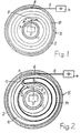
- Fig. 1 are schematically two, for example, circular walls 1 and 2 a cassette K shown. It is one for installation in the steering wheel Motor vehicle determined. To supply power to electronics 3 through their signal an impact bag can be triggered, the cassette K to the battery 4 of the Motor vehicle connected. The battery 4 is connected via an electrical line 5 a terminal 6 of the cassette K designed as a fixed point. The Electronic 3 is connected via an electrical line 7 to an end point 8 of the cassette K, which is movable in the direction of the double arrow 9. In principle, that could also Terminal 8 is fixed and the terminal 6 can be made movable. It could both end points 6 and 8 can also be movable.
- an FBL 10 with at least two electrical conductors attached.
- the conductors are preferably flat conductors educated.
- This embodiment of the FBL 10 is particularly thin and therefore takes very little space. In principle, the FBL 10 could also have round conductors.
- the structure of the FBL 10 and the type of its connection or completion to the Terminals 6 and 8 are not shown in more detail. You are in principle different variants are known and are not important here.
- the FBL 10 can, according to FIG. 1, in the cassette K between the two end points 6 and 8 in several turns, like a barrel of clocks, be arranged. Although the number of turns of a steering wheel is about is limited to six turns, more than six turns for the FBL 10 be provided. The rotary movement of the terminal 8 then makes one single turn of the FBL 10 not significantly noticeable. It will only be the Diameter of the winding body consisting of all turns of the FBL 10 reduced or enlarged.
- the FBL 10 can also be arranged in the cassette K in turns, which is divided into an outer winding area 11 and an inner winding area 12 are.
- the two winding areas 11 and 12 are identified by brackets. she comprise in the middle position shown in FIG. 2 or in the mounting position the cassette K two to three turns each. In the two winding areas 11 and 12, the turns of the FBL 10 have opposite winding directions.
- the Winding areas 11 and 12 are through an approximately U-shaped reversal point 13 connected to each other. Between the two winding areas 11 and 12 is a one-piece, ring-shaped guide body 14 attached, the Reversal point 13 includes.
- the guide body 14 is rotatable about its center and in the circumferential direction the cassette K, ie in the direction of the double arrow 9, easily movable. He can be as closed ring with a passage for the reversal point 13 of the FBL 10th be executed. But it can also be an open ring that is almost over 360 ° extends, as shown in Fig. 3.
- the guide body 14 is made preferably made of plastic. It is therefore very light, so that it moves easily in the Cassette K can be moved.
- the rotor 15 is rotatable relative to the stator 16 about the axis A of the cassette K. He is for this purpose, for example, connected to the steering wheel of a vehicle, in the Steering column cassette K is installed.
- enclosed receiving space 17 are FBL 10 and Compensating body 18 arranged, which in the illustrated embodiment as one-piece body is attached to the rotor 15. At the ends of the FBL 10 are further electrical lines 19 and 20 led out of the cassette K. connected.
- the surface 21 can with soundproofing material may be coated, for example with a fleece-shaped material consisting of fibers.
- the axial height H of the receiving space 17 of the cassette K should remain unchanged, regardless of the axial height of the FBL 10. If the FBL 10 with a is correspondingly large in number of conductors (left side of FIG. 4), then a correspondingly thin compensating body 18 with a small axial height is used. With a lower FBL 10 (right side of FIG. 4), an axially higher one Compensating body 18 used. The axial height of the compensating body 18 is each dimensioned so that the axial clearance remaining when the FBL 10 is inserted in the receiving space 17 of the cassette K is essentially filled by the same. The sum of the axial heights of FBL 10 and compensating body 18 is therefore in all Cases about constant. Between the compensating body 18 and the surface 21 of the Cassette K always has enough space for the FBL 10 to move between them can.
- the compensating body 18 can - as shown in Fig. 3 - in one piece as a ring be executed. But it can also be interrupted in the circumferential direction and consist of ring segments, for example.
- the compensating body 18 can also be made of ribs extending in the radial direction of the cassette K.
- material for the compensating body 18 is preferably plastic. Are suitable for example foamed materials, for example made of polyethylene, or Nonwovens. Such materials also have noise-reducing properties, so that no annoying rattling noises occur when operating a vehicle.
- the compensating body 18 is a one-piece body attached to the rotor 15. However, it could also be arranged on the stator 16. A division of the compensating body 18 into two partial bodies is also possible from which one is attached to the rotor 15 and the other to the stator 16.
Abstract
Description
Die Erfindung bezieht sich auf eine Vorrichtung zur Signalübertragung zwischen zwei Endstellen, zwischen denen mindestens eine in einer im wesentlichen kreisförmigen Kassette untergebrachte Leitung angeordnet ist, an die weiterführende Leitungen an den beiden Endstellen anschließbar sind und deren Länge größer als der Abstand der beiden Endstellen voneinander ist, bei welcher mindestens eine der beiden Endstellen relativ zu der anderen bewegbar ist und bei welcher die Kassette aus einem um ihre Achse drehbaren Rotor und einem feststehenden Stator besteht, die einen der Aufnahme der Leitung dienenden Aufnahmeraum begrenzen (EP 0 417 350 A1).The invention relates to a device for signal transmission between two End points, between which at least one is in a substantially circular Cassette housed line is arranged to the further lines the two end points can be connected and their length is greater than the distance between two end points is at each other, at least one of the two end points is movable relative to the other and in which the cassette from one to their Axis rotatable rotor and a fixed stator, which is one of the Limit the recording space serving the line (EP 0 417 350 A1).
Eine derartige Vorrichtung wird beispielsweise für die Übertragung eines Signals zum Auslösen des "Airbag" eines Prallschutzes für Kraftfahrzeuge eingesetzt, aber auch für eine Schiebetürverkabelung oder eine Lenkgetriebeverkabelung von Kraftfahrzeugen. Sie ist dazu im Regelfall zur Übertragung eines elektrischen oder optischen Signals im Lenkrad eines Kraftfahrzeugs untergebracht. "Leitung" im Sinne der Erfindung kann also eine elektrische oder eine optische Leitung sein. Ein wesentliches Problem für diese Vorrichtung ist die Signalübertragung zwischen feststehenden und beweglichen Teilen des Kraftfahrzeugs. Die für solche Fälle seit langem bekannten, der Stromübertragung dienenden Schleifkontakte bzw. Schleifringe sind einem Verschleiß unterworfen und insbesondere bei niedrigen Stromstärken wegen der schwankenden Übergangswiderstände nachteilig.Such a device is used, for example, for the transmission of a signal Triggering the "airbag" of an impact protection used for motor vehicles, but also for a sliding door wiring or a steering gear wiring of motor vehicles. It is usually for the transmission of an electrical or optical signal in the Steering wheel of a motor vehicle housed. "Line" in the sense of the invention can thus be an electrical or an optical line. A major problem for this device is the signal transmission between fixed and movable Parts of the motor vehicle. The long-known for such cases, the Sliding contacts or slip rings used for power transmission are subject to wear subject and especially at low currents due to the fluctuating Transfer resistances disadvantageous.
Bei der bekannten Vorrichtung nach der eingangs erwähnten EP 0 417 350 A1 wird für die Signalübertragung elektrischer Strom verwendet. Die Stromübertragung erfolgt durch eine beispielsweise nach Art eines Federhauses zu einem Wickelkörper gewickelte Flachband-Leitung - im folgenden kurz als "FBL" bezeichnet. Bei einer relativen Drehbewegung der beiden durch die FBL verbundenen Endstellen, "atmet" die aufgewickelte FBL wie die Feder einer Uhr. Die Windungen der gewickelten FBL werden in der einen Drehrichtung auf einen kleineren Durchmesser zusammengezogen. Sie gehen in der anderen Drehrichtung wieder auf einen größeren Durchmesser auf. Die Windungen der FBL gleiten dabei an den sie begrenzenden Flächen von Stator und Rotor.In the known device according to EP 0 417 350 A1 mentioned at the beginning used for signal transmission electrical current. The power transmission takes place for example, in the manner of a barrel to a winding body coiled ribbon cable - hereinafter referred to as "FBL". At a relative rotation of the two end points connected by the FBL, "breathes" the wound FBL like the spring of a watch. The turns of the wound FBL are reduced in one direction to a smaller diameter drawn together. They go back to one in the other direction larger diameter. The turns of the FBL slide against it delimiting surfaces of the stator and rotor.
In den in der Kassette solcher Vorrichtungen angebrachten FBL sind zwei oder mehr Leiter mit Abstand zueinander angeordnet. Die Breite der FBL nimmt also mit größer werdender Anzahl von Leitern zu, wenn die elektrischen Eigenschaften, insbesondere der ohmsche Widerstand, bei gleicher Länge der FBL unverändert bleiben sollen. Da die Leitung im Aufnahmeraum der Kassette hochkant angebracht ist, wird statt des Wortes "Breite" das Wort "Höhe" verwendet, womit bei montierter Leitung deren axiale Höhe im Aufnahmeraum der Kassette gemeint ist. Die Abmessungen der Kassette nach der bereits erwähnten EP 0 417 350 A1 sind für die Verwendung einer Leitung mit festliegender Leiterzahl gewählt. Das gilt auch für alle anderen bekannten Kassetten. Wenn eine andere Leiterzahl benötigt wird, als sie in der vorgesehenen Leitung vorhanden ist, müssen entweder die Abmessungen der Kassette an eine entsprechend niedrigere oder höhere Leitung angepaßt werden oder es wird von den in einer passenden Leitung vorhandenen Leitern nur ein Teil benutzt. Beide Varianten sind aufwendig.There are two or more in the FBLs installed in the cassette of such devices Conductors spaced apart. The width of the FBL therefore increases with the size increasing number of conductors when the electrical properties, in particular the ohmic resistance, should remain unchanged with the same length of the FBL. There the cable is placed upright in the receiving area of the cassette, instead of The word "width" uses the word "height", which means that when the cable is installed axial height in the receiving space of the cassette is meant. The dimensions of the Cassettes according to EP 0 417 350 A1 already mentioned are for the use of a Line with a fixed number of conductors selected. This also applies to all other known ones Cassettes. If a different number of conductors is required than the one provided Line is present, either the dimensions of the cassette to one correspondingly lower or higher line to be adjusted or it will be from the only a part of the conductors present in a suitable line is used. Both types are expensive.
Der Erfindung liegt die Aufgabe zugrunde, die eingangs geschilderte Vorrichtung so zu gestalten, daß sie in weiten Grenzen für FBL mit einer beliebigen Anzahl von Leitern einsetzbar ist.The invention has for its object the device described above to design them within wide limits for FBL with any number of Ladders can be used.
Diese Aufgabe wird gemäß der Erfindung dadurch gelöst,
- daß an mindestens einer der den Aufnahmeraum begrenzenden Flächen von Rotor und Stator ein Ausgleichskörper mit variabler axialer Höhe angebracht ist und
- daß bei gleichbleidender axialer Höhe des Aufnahmeraums der Kassette und variabler axialer Höhe der FBL, die axiale Höhe des Ausgleichskörpers derart bemessen ist, daß der zwischen der FBL und dem Rotor bzw. Stator der Kassette in axialer Richtung frei bleibende Raum im wesentlichen durch den Ausgleichskörper ausgefüllt ist.
- that a compensating body with variable axial height is attached to at least one of the surfaces of the rotor and stator delimiting the receiving space and
- that with constant axial height of the receiving space of the cassette and variable axial height of the FBL, the axial height of the compensating body is dimensioned such that the space remaining between the FBL and the rotor or stator of the cassette in the axial direction is essentially filled by the compensating body is.
Bei dieser Vorrichtung kann für viele unterschiedliche Anforderungen eine Kassette mit gleichbleibenden Abmessungen - insbesondere des Aufnahmeraums für die FBL-verwendet werden. Die Leiterzahl der jeweils einzusetzenden FBL kann so mit Vorteil an den jeweiligen Anwendungsfall angepaßt werden. Es können also FBL mit unterschiedlicher Höhe eingesetzt werden. Der damit variable axiale Freiraum innerhalb des Aufnahmeraums der Kassette wird für jeden Anwendungsfall durch einen Ausgleichskörper mit angepaßter Höhe aufgefüllt. In allen Fällen bleibt die Summe der axialen Höhen von FBL und Ausgleichskörper im wesentlichen konstant. Die FBL kann dadurch keine die Kontaktstellen belastenden großen Bewegungen in axialer Richtung ausführen, auch wenn ihre Höhe klein ist im Verhältnis zur Höhe des Aufnahmeraums. Auch ein Verheddern einzelner Windungen der FBL ist so verhindert. Der jeweils angepaßte Ausgleichskörper kann bei Einsatz von geeignetem Material neben seiner Funktion als Höhenausgleich stets auch die Funktion der Geräuschdämmung übernehmen.With this device, a cassette can be used for many different requirements constant dimensions - especially the recording space used for the FBL become. The number of conductors of the FBL to be used in each case can thus be advantageous be adapted to the respective application. So you can use FBL different heights are used. The variable axial clearance within the receiving space of the cassette for each application filled a compensating body with an adjusted height. In all cases it remains Sum of the axial heights of the FBL and compensating body is essentially constant. As a result, the FBL cannot make large movements in contact with the contact points axial direction, even if their height is small in relation to the height of the Recording room. It is also the case that individual turns of the FBL get tangled prevented. The respective compensating body can be adjusted when using a suitable one In addition to its function as height compensation, material also always functions as a Take over noise insulation.
Ausführungsbeispiele des Erfindungsgegenstandes sind in den Zeichnungen dargestellt.Embodiments of the subject of the invention are in the drawings shown.
Es zeigen:
Die Erfindung wird im folgenden - stellvertretend auch für andere Ausführungsformen - für eine Kassette beschrieben, in der eine Flachbandleitung (FBL) mit elektrischen Leitern angebracht ist. Statt der FBL könnte aber auch eine Leitung mit mindestens einem Lichtleiter eingesetzt werden. Auch eine kombinierte Leitung mit elektrischen und optischen Leitern könnte verwendet werden.The invention will be hereinafter - representative of other embodiments - Described for a cassette in which a ribbon cable (FBL) with electrical Ladders is attached. Instead of the FBL, a line with at least one could an optical fiber can be used. Also a combined line with electrical and optical conductors could be used.
In Fig. 1 sind schematisch zwei beispielsweise kreisförmig ausgebildete Wände 1 und
2 einer Kassette K dargestellt. Sie ist für den Einbau in das Lenkrad eines
Kraftfahrzeugs bestimmt. Zur Stromversorgung einer Elektronik 3, durch deren Signal
ein Prallsack ausgelöst werden kann, ist die Kassette K an die Batterie 4 des
Kraftfahrzeugs angeschlossen. Die Batterie 4 ist über eine elektrische Leitung 5 mit
einer als Festpunkt ausgeführten Endstelle 6 der Kassette K verbunden. Die Elektronik
3 ist über eine elektrische Leitung 7 an eine Endstelle 8 der Kassette K angeschlossen,
die in Richtung des Doppelpfeiles 9 bewegbar ist. Grundsätzlich könnten auch die
Endstelle 8 feststehend und die Endstelle 6 bewegbar ausgeführt sein. Es könnten
auch beide Endstellen 6 und 8 bewegbar sein.In Fig. 1 are schematically two, for example, circular walls 1 and
2 a cassette K shown. It is one for installation in the steering wheel
Motor vehicle determined. To supply power to electronics 3 through their signal
an impact bag can be triggered, the cassette K to the
Zwischen den beiden Endstellen 6 und 8 ist eine FBL 10 mit mindestens zwei
elektrischen Leitern angebracht. Die Leiter sind vorzugsweise als Flachleiter
ausgebildet. Diese Ausführungsform der FBL 10 ist besonders dünn und nimmt daher
sehr wenig Raum ein. Grundsätzlich könnte die FBL 10 aber auch runde Leiter haben.
Der Aufbau der FBL 10 und die Art ihres Anschlusses bzw. Abschlusses an den
Endstellen 6 und 8 sind nicht genauer dargestellt. Sie sind prinzipiell in
unterschiedlichen Varianten bekannt und hier nicht von Bedeutung.Between the two
Die FBL 10 kann gemäß Fig. 1 in der Kassette K zwischen den beiden Endstellen 6
und 8 in mehreren Windungen, also nach Art eines Federhauses von Uhren,
angeordnet sein. Obwohl die Anzahl der Umdrehungen eines Lenkrades auf etwa
sechs Umdrehungen begrenzt ist, sollen mehr als sechs Windungen für die FBL 10
vorgesehen sein. Die Drehbewegung der Endstelle 8 macht sich dann für eine
einzelne Windung der FBL 10 nicht wesentlich bemerkbar. Es wird lediglich der
Durchmesser des aus allen Windungen der FBL 10 bestehenden Wickelkörpers
verkleinert bzw. vergrößert.The FBL 10 can, according to FIG. 1, in the cassette K between the two
Die FBL 10 kann gemäß Fig. 2 in der Kassette K auch in Windungen angeordnet sein,
die in einen äußeren Wickelbereich 11 und einen inneren Wickelbereich 12 unterteilt
sind. Die beiden Wickelbereiche 11 und 12 sind durch Klammern gekennzeichnet. Sie
umfassen in der aus Fig. 2 ersichtlichen Mittelstellung bzw. in der Montageposition
der Kassette K jeweils zwei bis drei Windungen. In den beiden Wickelbereichen 11
und 12 haben die Windungen der FBL 10 entgegengesetzte Wickelrichtungen. Die
Wickelbereiche 11 und 12 sind durch eine etwa U-förmig ausgeführte Umkehrstelle
13 miteinander verbunden. Zwischen den beiden Wickelbereichen 11 und 12 ist ein
einteiliger, ringförmig ausgeführter Führungskörper 14 angebracht, der die
Umkehrstelle 13 umfaßt. 2, the
Der Führungskörper 14 ist um seinen Mittelpunkt drehbar und in Umfangsrichtung
der Kassette K, also in Richtung des Doppelpfeils 9, leicht beweglich. Er kann als
geschlossener Ring mit einem Durchlaß für die Umkehrstelle 13 der FBL 10
ausgeführt sein. Er kann aber auch ein offener Ring sein, der sich nahezu über 360°
erstreckt, so wie es in Fig. 3 dargestellt ist. Der Führungskörper 14 besteht
vorzugsweise aus Kunststoff. Er ist dadurch sehr leicht, so daß er leichtgängig in der
Kassette K bewegt werden kann.The
Die Kassette K besteht gemäß Fig. 3 aus einem Rotor 15 und einem Stator 16. Der
Rotor 15 ist gegenüber dem Stator 16 um die Achse A der Kassette K drehbar. Er ist
dazu beispielsweise mit dem Lenkrad eines Fahrzeugs verbunden, in dessen
Lenksäule die Kassette K eingebaut ist. In dem vom Rotor 15 einerseits und vom
Stator 16 andererseits umschlossenen Aufnahmeraum 17 sind die FBL 10 und ein
Ausgleichskörper 18 angeordnet, der im dargestellten Ausführungsbeispiel als
einteiliger Körper am Rotor 15 angebracht ist. An den Enden der FBL 10 sind
weiterführende, aus der Kassette K herausgeführte elektrische Leitungen 19 und 20
angeschlossen.3 consists of a
Bei einer Drehung des Rotors 15 werden die FBL 10 bzw. deren Windungen quer zur
Achse A der Kassette K bewegt. Zwischen FBL 10 und Ausgleichskörper 18 liegt daher
ein ausreichend großer Spalt, durch den sichergestellt ist, daß die FBL 10 nicht
eingeklemmt wird. Bei der Bewegung der FBL 10 gleiten deren Windungen auf der
nach innen weisenden Fläche 21 des Stators 16. Die Fläche 21 kann mit
geräuschdämmendem Material beschichtet sein, beispielsweise mit einem
vliesförmigen, aus Fasern bestehenden Material.When the
Die axiale Höhe H des Aufnahmeraums 17 der Kassette K soll unverändert bleiben,
unabhängig von der axialen Höhe der FBL 10. Wenn die FBL 10 mit einer
entsprechend großen Anzahl von Leitern hoch ist (linke Seite von Fig. 4), dann wird
ein entsprechend dünner Ausgleichskörper 18 mit geringer axialer Höhe eingesetzt.
Bei einer niedrigeren FBL 10 (rechte Seite von Fig. 4) wird ein axial höherer
Ausgleichskörper 18 verwendet. Die axiale Höhe des Ausgleichskörpers 18 wird
jeweils so bemessen, daß der bei eingesetzter FBL 10 verbleibende axiale Freiraum
im Aufnahmeraum 17 der Kassette K im wesentlichen von demselben ausgefüllt wird.
Die Summe der axialen Höhen von FBL 10 und Ausgleichskörper 18 ist also in allen
Fällen etwa konstant. Zwischen dem Ausgleichskörper 18 und der Fläche 21 der
Kassette K bleibt stets genug Freiraum, damit die FBL 10 sich dazwischen bewegen
kann.The axial height H of the receiving
Der Ausgleichskörper 18 kann - so wie in Fig. 3 dargestellt - einteilig als Ring
ausgeführt sein. Er kann aber in Umfangsrichtung auch unterbrochen sein und
beispielsweise aus Ringsegmenten bestehen. Der Ausgleichskörper 18 kann auch aus
in radialer Richtung der Kassette K verlaufenden Rippen bestehen. Als Material für
den Ausgleichskörper 18 wird vorzugsweise Kunststoff verwendet. Geeignet sind
beispielsweise aufgeschäumte Materialien, beispielsweise aus Polyethylen, oder auch
Vliesstoffe. Solche Materialien haben gleichzeitig geräuschdämmende Eigenschaften,
so daß beim Betrieb eines Fahrzeugs keine störenden Klappergeräusche entstehen.The compensating
Im dargestellten Ausführungsbeispiel ist der Ausgleichskörper 18 als einteiliger Körper
am Rotor 15 angebracht. Er könnte aber auch am Stator 16 angeordnet werden.
Auch eine Aufteilung des Ausgleichskörpers 18 in zwei Teilkörper ist möglich, von
denen einer am Rotor 15 und der andere am Stator 16 angebracht ist.In the illustrated embodiment, the compensating
Claims (7)
Applications Claiming Priority (2)
| Application Number | Priority Date | Filing Date | Title |
|---|---|---|---|
| DE19960205 | 1999-12-14 | ||
| DE19960205A DE19960205A1 (en) | 1999-12-14 | 1999-12-14 | Device for signal transmission between two end points |
Publications (3)
| Publication Number | Publication Date |
|---|---|
| EP1109271A2 true EP1109271A2 (en) | 2001-06-20 |
| EP1109271A3 EP1109271A3 (en) | 2002-01-16 |
| EP1109271B1 EP1109271B1 (en) | 2004-02-04 |
Family
ID=7932584
Family Applications (1)
| Application Number | Title | Priority Date | Filing Date |
|---|---|---|---|
| EP00403189A Expired - Lifetime EP1109271B1 (en) | 1999-12-14 | 2000-11-16 | Series of devices for signal transmission between two end stations |
Country Status (5)
| Country | Link |
|---|---|
| US (1) | US6641414B2 (en) |
| EP (1) | EP1109271B1 (en) |
| AT (1) | ATE259107T1 (en) |
| DE (2) | DE19960205A1 (en) |
| TR (1) | TR200400240T4 (en) |
Cited By (1)
| Publication number | Priority date | Publication date | Assignee | Title |
|---|---|---|---|---|
| DE10255277A1 (en) * | 2002-11-26 | 2004-06-03 | Hesse & Knipps Gmbh | Arrangement for contacting between two components |
Families Citing this family (4)
| Publication number | Priority date | Publication date | Assignee | Title |
|---|---|---|---|---|
| DE10260168A1 (en) * | 2002-12-20 | 2004-07-01 | Volkswagen Ag | Operating device for automatic transmission in motor vehicle, has normally-closed contacts of functionally-equivalent switches connected in series, and normally-closed contacts connected in parallel |
| US20050048821A1 (en) * | 2003-08-25 | 2005-03-03 | Bolen Patrick A. | Clockspring flat cable termination |
| ATE408909T1 (en) | 2005-12-19 | 2008-10-15 | Nexans | DEVICE FOR SIGNAL TRANSMISSION BETWEEN TERMINAL POINTS |
| DE102015118543A1 (en) * | 2015-10-29 | 2017-05-04 | Valeo Schalter Und Sensoren Gmbh | Protective cover for a coil spring housing, clock spring housing assembly and vehicle having such a clock spring housing assembly |
Citations (6)
| Publication number | Priority date | Publication date | Assignee | Title |
|---|---|---|---|---|
| EP0243047A2 (en) * | 1986-04-15 | 1987-10-28 | The Furukawa Electric Co., Ltd. | Connector device for a transmission line connecting two relatively rotating members |
| EP0401028A2 (en) * | 1989-05-31 | 1990-12-05 | The Furukawa Electric Co., Ltd. | Connector devices |
| US5137463A (en) * | 1990-09-20 | 1992-08-11 | Alps Electric Co., Ltd. | Clock spring |
| EP0417350B1 (en) * | 1989-09-12 | 1994-06-01 | Petri AG | Electrical connector device to bridge line interruptions between two relatively rotating parts |
| DE4329119A1 (en) * | 1993-08-30 | 1995-03-02 | Petri Ag | Power line connector for bridging wire breaks between mutually rotatable parts |
| DE29510286U1 (en) * | 1995-06-26 | 1995-09-07 | Alcatel Kabel Ag | Device for signal transmission between two end points |
Family Cites Families (3)
| Publication number | Priority date | Publication date | Assignee | Title |
|---|---|---|---|---|
| GB8423016D0 (en) * | 1984-09-12 | 1984-10-17 | Mcgeoch & Co Birmingham Ltd Wi | Coupling device |
| JPH0636040Y2 (en) * | 1988-03-31 | 1994-09-21 | アルプス電気株式会社 | Cable reel |
| JPH08222340A (en) * | 1994-12-14 | 1996-08-30 | Yazaki Corp | Electrically connecting apparatus between steering wheel and steering column |
-
1999
- 1999-12-14 DE DE19960205A patent/DE19960205A1/en not_active Withdrawn
-
2000
- 2000-11-16 EP EP00403189A patent/EP1109271B1/en not_active Expired - Lifetime
- 2000-11-16 AT AT00403189T patent/ATE259107T1/en not_active IP Right Cessation
- 2000-11-16 DE DE50005188T patent/DE50005188D1/en not_active Expired - Lifetime
- 2000-11-16 TR TR2004/00240T patent/TR200400240T4/en unknown
- 2000-12-13 US US09/734,683 patent/US6641414B2/en not_active Expired - Fee Related
Patent Citations (6)
| Publication number | Priority date | Publication date | Assignee | Title |
|---|---|---|---|---|
| EP0243047A2 (en) * | 1986-04-15 | 1987-10-28 | The Furukawa Electric Co., Ltd. | Connector device for a transmission line connecting two relatively rotating members |
| EP0401028A2 (en) * | 1989-05-31 | 1990-12-05 | The Furukawa Electric Co., Ltd. | Connector devices |
| EP0417350B1 (en) * | 1989-09-12 | 1994-06-01 | Petri AG | Electrical connector device to bridge line interruptions between two relatively rotating parts |
| US5137463A (en) * | 1990-09-20 | 1992-08-11 | Alps Electric Co., Ltd. | Clock spring |
| DE4329119A1 (en) * | 1993-08-30 | 1995-03-02 | Petri Ag | Power line connector for bridging wire breaks between mutually rotatable parts |
| DE29510286U1 (en) * | 1995-06-26 | 1995-09-07 | Alcatel Kabel Ag | Device for signal transmission between two end points |
Cited By (1)
| Publication number | Priority date | Publication date | Assignee | Title |
|---|---|---|---|---|
| DE10255277A1 (en) * | 2002-11-26 | 2004-06-03 | Hesse & Knipps Gmbh | Arrangement for contacting between two components |
Also Published As
| Publication number | Publication date |
|---|---|
| TR200400240T4 (en) | 2004-03-22 |
| EP1109271B1 (en) | 2004-02-04 |
| ATE259107T1 (en) | 2004-02-15 |
| DE50005188D1 (en) | 2004-03-11 |
| US6641414B2 (en) | 2003-11-04 |
| EP1109271A3 (en) | 2002-01-16 |
| DE19960205A1 (en) | 2001-06-28 |
| US20010012713A1 (en) | 2001-08-09 |
Similar Documents
| Publication | Publication Date | Title |
|---|---|---|
| DE3406327C2 (en) | ||
| DE4216526A1 (en) | Signal transmitting device for cassette line in vehicle air-bag system - has spring element mounted on rotor which fixes cassette onto stator in assembly position | |
| EP0706914B1 (en) | Device for signal transmission between two extremities | |
| EP1109271B1 (en) | Series of devices for signal transmission between two end stations | |
| EP0735632B1 (en) | Device for signal transmission between two terminals | |
| DE19805106C1 (en) | Absolute zero position detection device for automobile steering device | |
| DE19525686C2 (en) | Device for signal transmission between two end points | |
| EP0623442B1 (en) | Process for manufacturing a device for the transmission of signals between two terminals | |
| EP0735631B1 (en) | Device for signal transmission between two terminals | |
| DE102007055392A1 (en) | Anti-rotation of a rotor and a housing of a winding tape and a winding tape | |
| EP1615303A2 (en) | Device for signal transfer between two end positions | |
| EP0536599B1 (en) | Device for current transmission between two end positions | |
| EP0591730B1 (en) | Signal transmission device between two end portions | |
| EP1255330B1 (en) | Device for transferring current between two end positions | |
| EP0693806B1 (en) | Device for signal transmission between two terminals | |
| EP1800957B1 (en) | Device for signal and current transmission between terminals | |
| EP1324435B1 (en) | Electrical connector between two end positions | |
| EP0834968B1 (en) | Device for transferring current between two terminals moving relatively to one another | |
| EP1808940B1 (en) | Device for transmitting signals between terminals | |
| DE4225119A1 (en) | Transmission device coupling two relatively movable points | |
| EP0670246B1 (en) | Signal transmission installation between two terminals | |
| EP0803406B1 (en) | Device for transmitting signals between two terminals | |
| EP0952292A1 (en) | Closing device, especially for automatically closing vehicle doors | |
| EP2028730B1 (en) | Device for signal and current transmission between terminals | |
| EP2364882B1 (en) | Assembly for electrically linking two electric contact points |
Legal Events
| Date | Code | Title | Description |
|---|---|---|---|
| PUAI | Public reference made under article 153(3) epc to a published international application that has entered the european phase |
Free format text: ORIGINAL CODE: 0009012 |
|
| AK | Designated contracting states |
Kind code of ref document: A2 Designated state(s): AT BE CH CY DE DK ES FI FR GB GR IE IT LI LU MC NL PT SE TR |
|
| AX | Request for extension of the european patent |
Free format text: AL;LT;LV;MK;RO;SI |
|
| RAP1 | Party data changed (applicant data changed or rights of an application transferred) |
Owner name: NEXANS |
|
| PUAL | Search report despatched |
Free format text: ORIGINAL CODE: 0009013 |
|
| AK | Designated contracting states |
Kind code of ref document: A3 Designated state(s): AT BE CH CY DE DK ES FI FR GB GR IE IT LI LU MC NL PT SE TR |
|
| AX | Request for extension of the european patent |
Free format text: AL;LT;LV;MK;RO;SI |
|
| 17P | Request for examination filed |
Effective date: 20011208 |
|
| AKX | Designation fees paid | ||
| REG | Reference to a national code |
Ref country code: DE Ref legal event code: 8566 |
|
| 17Q | First examination report despatched |
Effective date: 20021014 |
|
| RBV | Designated contracting states (corrected) |
Designated state(s): AT BE CH CY DE DK ES FI FR GB GR IE IT LI LU MC NL PT SE TR |
|
| GRAH | Despatch of communication of intention to grant a patent |
Free format text: ORIGINAL CODE: EPIDOS IGRA |
|
| RTI1 | Title (correction) |
Free format text: SERIES OF DEVICES FOR SIGNAL TRANSMISSION BETWEEN TWO END STATIONS |
|
| GRAS | Grant fee paid |
Free format text: ORIGINAL CODE: EPIDOSNIGR3 |
|
| GRAA | (expected) grant |
Free format text: ORIGINAL CODE: 0009210 |
|
| AK | Designated contracting states |
Kind code of ref document: B1 Designated state(s): AT BE CH CY DE DK ES FI FR GB GR IE IT LI LU MC NL PT SE TR |
|
| PG25 | Lapsed in a contracting state [announced via postgrant information from national office to epo] |
Ref country code: FI Free format text: LAPSE BECAUSE OF FAILURE TO SUBMIT A TRANSLATION OF THE DESCRIPTION OR TO PAY THE FEE WITHIN THE PRESCRIBED TIME-LIMIT Effective date: 20040204 Ref country code: IE Free format text: LAPSE BECAUSE OF FAILURE TO SUBMIT A TRANSLATION OF THE DESCRIPTION OR TO PAY THE FEE WITHIN THE PRESCRIBED TIME-LIMIT Effective date: 20040204 Ref country code: NL Free format text: LAPSE BECAUSE OF FAILURE TO SUBMIT A TRANSLATION OF THE DESCRIPTION OR TO PAY THE FEE WITHIN THE PRESCRIBED TIME-LIMIT Effective date: 20040204 Ref country code: CY Free format text: LAPSE BECAUSE OF FAILURE TO SUBMIT A TRANSLATION OF THE DESCRIPTION OR TO PAY THE FEE WITHIN THE PRESCRIBED TIME-LIMIT Effective date: 20040204 |
|
| REG | Reference to a national code |
Ref country code: GB Ref legal event code: FG4D Free format text: NOT ENGLISH |
|
| REG | Reference to a national code |
Ref country code: CH Ref legal event code: EP |
|
| GBT | Gb: translation of ep patent filed (gb section 77(6)(a)/1977) |
Effective date: 20040204 |
|
| REG | Reference to a national code |
Ref country code: IE Ref legal event code: FG4D Free format text: GERMAN |
|
| REF | Corresponds to: |
Ref document number: 50005188 Country of ref document: DE Date of ref document: 20040311 Kind code of ref document: P |
|
| PG25 | Lapsed in a contracting state [announced via postgrant information from national office to epo] |
Ref country code: GR Free format text: LAPSE BECAUSE OF FAILURE TO SUBMIT A TRANSLATION OF THE DESCRIPTION OR TO PAY THE FEE WITHIN THE PRESCRIBED TIME-LIMIT Effective date: 20040504 Ref country code: DK Free format text: LAPSE BECAUSE OF FAILURE TO SUBMIT A TRANSLATION OF THE DESCRIPTION OR TO PAY THE FEE WITHIN THE PRESCRIBED TIME-LIMIT Effective date: 20040504 |
|
| PG25 | Lapsed in a contracting state [announced via postgrant information from national office to epo] |
Ref country code: ES Free format text: LAPSE BECAUSE OF FAILURE TO SUBMIT A TRANSLATION OF THE DESCRIPTION OR TO PAY THE FEE WITHIN THE PRESCRIBED TIME-LIMIT Effective date: 20040515 |
|
| NLV1 | Nl: lapsed or annulled due to failure to fulfill the requirements of art. 29p and 29m of the patents act | ||
| REG | Reference to a national code |
Ref country code: IE Ref legal event code: FD4D |
|
| ET | Fr: translation filed | ||
| PLBE | No opposition filed within time limit |
Free format text: ORIGINAL CODE: 0009261 |
|
| STAA | Information on the status of an ep patent application or granted ep patent |
Free format text: STATUS: NO OPPOSITION FILED WITHIN TIME LIMIT |
|
| 26N | No opposition filed |
Effective date: 20041105 |
|
| PGFP | Annual fee paid to national office [announced via postgrant information from national office to epo] |
Ref country code: MC Payment date: 20051026 Year of fee payment: 6 |
|
| PGFP | Annual fee paid to national office [announced via postgrant information from national office to epo] |
Ref country code: AT Payment date: 20051111 Year of fee payment: 6 |
|
| PGFP | Annual fee paid to national office [announced via postgrant information from national office to epo] |
Ref country code: CH Payment date: 20051115 Year of fee payment: 6 |
|
| PGFP | Annual fee paid to national office [announced via postgrant information from national office to epo] |
Ref country code: LU Payment date: 20051125 Year of fee payment: 6 |
|
| PGFP | Annual fee paid to national office [announced via postgrant information from national office to epo] |
Ref country code: BE Payment date: 20060117 Year of fee payment: 6 |
|
| PG25 | Lapsed in a contracting state [announced via postgrant information from national office to epo] |
Ref country code: AT Free format text: LAPSE BECAUSE OF NON-PAYMENT OF DUE FEES Effective date: 20061116 |
|
| PG25 | Lapsed in a contracting state [announced via postgrant information from national office to epo] |
Ref country code: LI Free format text: LAPSE BECAUSE OF NON-PAYMENT OF DUE FEES Effective date: 20061130 Ref country code: MC Free format text: LAPSE BECAUSE OF NON-PAYMENT OF DUE FEES Effective date: 20061130 Ref country code: CH Free format text: LAPSE BECAUSE OF NON-PAYMENT OF DUE FEES Effective date: 20061130 Ref country code: BE Free format text: LAPSE BECAUSE OF NON-PAYMENT OF DUE FEES Effective date: 20061130 |
|
| REG | Reference to a national code |
Ref country code: CH Ref legal event code: PL |
|
| BERE | Be: lapsed |
Owner name: *NEXANS Effective date: 20061130 |
|
| PG25 | Lapsed in a contracting state [announced via postgrant information from national office to epo] |
Ref country code: PT Free format text: LAPSE BECAUSE OF NON-PAYMENT OF DUE FEES Effective date: 20040704 |
|
| PG25 | Lapsed in a contracting state [announced via postgrant information from national office to epo] |
Ref country code: LU Free format text: LAPSE BECAUSE OF NON-PAYMENT OF DUE FEES Effective date: 20061116 |
|
| PGFP | Annual fee paid to national office [announced via postgrant information from national office to epo] |
Ref country code: GB Payment date: 20091119 Year of fee payment: 10 |
|
| PGFP | Annual fee paid to national office [announced via postgrant information from national office to epo] |
Ref country code: SE Payment date: 20101112 Year of fee payment: 11 |
|
| GBPC | Gb: european patent ceased through non-payment of renewal fee |
Effective date: 20101116 |
|
| PG25 | Lapsed in a contracting state [announced via postgrant information from national office to epo] |
Ref country code: GB Free format text: LAPSE BECAUSE OF NON-PAYMENT OF DUE FEES Effective date: 20101116 |
|
| REG | Reference to a national code |
Ref country code: SE Ref legal event code: EUG |
|
| PG25 | Lapsed in a contracting state [announced via postgrant information from national office to epo] |
Ref country code: SE Free format text: LAPSE BECAUSE OF NON-PAYMENT OF DUE FEES Effective date: 20111117 |
|
| PGFP | Annual fee paid to national office [announced via postgrant information from national office to epo] |
Ref country code: FR Payment date: 20131120 Year of fee payment: 14 |
|
| PGFP | Annual fee paid to national office [announced via postgrant information from national office to epo] |
Ref country code: TR Payment date: 20141030 Year of fee payment: 15 |
|
| REG | Reference to a national code |
Ref country code: FR Ref legal event code: ST Effective date: 20150731 |
|
| PG25 | Lapsed in a contracting state [announced via postgrant information from national office to epo] |
Ref country code: FR Free format text: LAPSE BECAUSE OF NON-PAYMENT OF DUE FEES Effective date: 20141201 |
|
| PGFP | Annual fee paid to national office [announced via postgrant information from national office to epo] |
Ref country code: IT Payment date: 20151125 Year of fee payment: 16 Ref country code: DE Payment date: 20151119 Year of fee payment: 16 |
|
| REG | Reference to a national code |
Ref country code: DE Ref legal event code: R119 Ref document number: 50005188 Country of ref document: DE |
|
| PG25 | Lapsed in a contracting state [announced via postgrant information from national office to epo] |
Ref country code: TR Free format text: LAPSE BECAUSE OF NON-PAYMENT OF DUE FEES Effective date: 20151116 |
|
| PG25 | Lapsed in a contracting state [announced via postgrant information from national office to epo] |
Ref country code: IT Free format text: LAPSE BECAUSE OF NON-PAYMENT OF DUE FEES Effective date: 20161116 |
|
| PG25 | Lapsed in a contracting state [announced via postgrant information from national office to epo] |
Ref country code: DE Free format text: LAPSE BECAUSE OF NON-PAYMENT OF DUE FEES Effective date: 20170601 |