EP1109263B1 - Electrical connector - Google Patents
Electrical connector Download PDFInfo
- Publication number
- EP1109263B1 EP1109263B1 EP00310468A EP00310468A EP1109263B1 EP 1109263 B1 EP1109263 B1 EP 1109263B1 EP 00310468 A EP00310468 A EP 00310468A EP 00310468 A EP00310468 A EP 00310468A EP 1109263 B1 EP1109263 B1 EP 1109263B1
- Authority
- EP
- European Patent Office
- Prior art keywords
- retainer
- housing
- protruding
- face
- tubular housing
- Prior art date
- Legal status (The legal status is an assumption and is not a legal conclusion. Google has not performed a legal analysis and makes no representation as to the accuracy of the status listed.)
- Expired - Lifetime
Links
Images


Classifications
-
- H—ELECTRICITY
- H01—ELECTRIC ELEMENTS
- H01R—ELECTRICALLY-CONDUCTIVE CONNECTIONS; STRUCTURAL ASSOCIATIONS OF A PLURALITY OF MUTUALLY-INSULATED ELECTRICAL CONNECTING ELEMENTS; COUPLING DEVICES; CURRENT COLLECTORS
- H01R13/00—Details of coupling devices of the kinds covered by groups H01R12/70 or H01R24/00 - H01R33/00
- H01R13/40—Securing contact members in or to a base or case; Insulating of contact members
- H01R13/42—Securing in a demountable manner
- H01R13/436—Securing a plurality of contact members by one locking piece or operation
- H01R13/4361—Insertion of locking piece perpendicular to direction of contact insertion
- H01R13/4362—Insertion of locking piece perpendicular to direction of contact insertion comprising a temporary and a final locking position
Definitions
- the present invention relates to a connector having a terminal retaining body provided with cavities and located within a cylindrical body.
- This type of connector includes those having a connector housing formed in two pieces.
- this connector comprises a connector housing 1, consisting of a cylindrical outer housing 2 which is open to the anterior, and an inner housing 3 which fits within the outer housing 2. Cavities 5, into which terminal fittings 4 can be inserted are formed in the inner housing 3. A retainer attachment hole 6, which opens to the side of the cavities 5, is formed in the inner housing 3. A retainer 7 is inserted into the retainer attachment hole 6, thereby retaining the terminal fittings 4, which have been inserted into the cavities 5. The inner housing 3 is then housed within the outer housing 2.
- the retainer 7 is sometimes inserted to an insufficient depth.
- the retainer 7 retains the terminal fittings 4 to a greater degree the more deeply it is inserted. Consequently, the terminal fittings 4 are poorly retained when the retainer 7 is inserted to an insufficient depth.
- the present invention has taken the above problem into consideration, and aims to present a connector in which a terminal retaining body provided with a retainer can be fitted smoothly into a a cylindrical body.
- US-A-5518428 discloses an electrical connector having a tubular housing with a guiding member on an internal face thereof, this guiding member being adapted to engage a retainer in a protruding condition, and to urge the retainer to a non-protruding condition as a terminal retaining body is received in the housing.
- an electrical connector comprising three parts: a terminal retaining body having cavities to receive electrical terminals, a retainer insertable into said terminal retaining body from a protruding to a non-protruding condition and adapted to retain electrical terminals therein; and a tubular housing to receive the terminal retaining body and retainer therein; characterised in that a first guiding member is provided on the inner face of said tubular housing, the first guiding member being adapted to engage said retainer in a protruding condition, and to urge said retainer to a non-protruding condition as the terminal retaining body is received within said tubular housing; wherein said first guiding member comprises a tapered face for engagement with said retainer, said tapered face being directed inwardly of the housing with respect to the direction of insertion; and wherein said tubular housing includes a guiding groove in its inner face, the guiding groove guiding a protruding retainer to said tapered face.
- the housing preferably is approximately rectangular, the first guiding member being about half way along one side thereof.
- the connector is easier to waterproof.
- a mating connector is insertable in the tubular housing for electrical engagement with the terminal retaining body, and this mating connector has a protrusion engageable in the guiding groove of the tubular housing.
- the tubular housing may include a second guiding member to urge a retainer of the mating connector into a non-protruding condition.
- first and second guiding members are opposite.
- a waterproof connector is formed from a male connector housing 10 and a female connector housing 50.
- the male housing 10 comprises an inner housing 30 fitting within a cylindrical outer housing 11.
- the outer housing 11 has an approximately cylindrical shape and is provided with a hood 12 which is open to the anterior.
- Terminal housing chambers 14 are formed in the posterior side of the outer housing 11. These terminal housing chambers 14 are provided with an upper and lower layer of outer cavities 13 into which male terminal fittings 17 can be inserted.
- the lower layer of the outer cavities has four mutually aligned large chambers, and the upper layer has five mutually aligned small chambers.
- the hood 12 is formed so that the inner housing 30 can be fitted therein.
- a pair of fitting protrusions 15 are formed on innermost sides of inner faces of the hood 12. These fit with fitting members 34 formed on the inner housing 30, thereby maintaining the inner housing 30 in a fitted state with the hood 12.
- a rubber ring 16 is attached to the immediate anterior of the inner housing 30, this fitting tightly with an inner circumference face of the hood 12.
- the inner housing 30 is provided with an upper and lower layer of inner cavities 32, a separating wall 31 being provided therebetween at an approximately central location relative to the up-down direction of the inner housing 30.
- these inner cavities 32 pass through, at their posterior, to the outer cavities 13 when the inner housing 30 is in a fitted state within the outer housing 11.
- the male terminal fittings 17, which have been passed through the outer cavities 13, are housed within these inner cavities 32.
- a lance 19, formed on a box member 18 of each male terminal fitting 17, is capable of engaging resiliently with a stopping groove 33 formed in an inner face of each inner cavity 32.
- Each male terminal fitting 17 is provided with a tab 20 and a barrel member 22.
- the tab 20 is formed at the anterior side of the box member 18.
- the barrel member 22 has a rubber stopper 21 clamped thereto, an electric wire being attached to this rubber stopper 21.
- the rubber stoppers 21 fit tightly with inner circumference faces of the outer cavities 13, thereby waterproofing the cavities 13 and 32.
- posterior ends of the side faces of the inner housing 30 have the pair of fitting members 34 formed thereon.
- a retainer attachment hole 35 which opens onto both side faces of the inner housing 30, is formed to the anterior of the fitting members 34.
- a retainer 40 can be inserted into this retainer attachment hole 35 from the right side (relative to Figure 3).
- the retainer attachment hole 35 passes through the separating wall 31 in a width-wise direction thereof, and lower faces of the upper cavities 32 and upper faces of the lower cavities 32 open onto this retainer attachment hole 35.
- a temporary retaining hole 36 and a main retaining hole 37 both being open to the anterior, are formed in a wall portion located towards the anterior side of the retainer attachment hole 35.
- the temporary retaining hole 36 and the main retaining hole 37 are formed in an approximately central location relative to the width-wise direction of the wall portion, and are aligned from right to left relative to Figure 3.
- a retaining protrusion 44 of the retainer 40 engages with the temporary retaining hole 36 or the main retaining hole 37, thereby allowing the retainer 40 to be maintained at either of two separate locations along the width-wise direction of the retainer attachment hole 35.
- a retainer operating hole 38 is provided to the right (relative to Figure 3) of the temporary retaining hole 36. A jig or the like can be inserted via this retainer operating hole 38 in order to operate the retainer 40 within the retainer attachment hole 35.
- the retainer 40 is provided with a long and narrow plate-shaped main body 41.
- a pressing operating member 42 protrudes towards the anterior from a right edge (relative to Figure 3) of the main body 41.
- This pressing operating member 42 allows a pressing operation while the retainer 40 is attached to the inner housing 30.
- An arch-shaped bending member 43 protrudes from an anterior face of the main body 41 at a location to the left of the pressing operating member 42 (a space remains between the bending member 43 and the pressing operating member 42).
- the retaining protrusion 44 protrudes from the centre of an anterior face of the bending member 43. When the retainer 40 is to be moved within the retainer attachment hole 35, the retaining protrusion 44 is pressed, thereby bending the centre of the bending member 43 in a concave manner (see Figure 12).
- stopping protrusions 45 protrude from upper and lower faces of the main body 41.
- Four stopping protrusions 45 are formed on the lower face, and five stopping protrusions 45 are formed on the upper face, these stopping protrusions 45 being formed in locations which correspond to spaces between the inner cavities 32.
- the stopping protrusions 45 engage with the male terminal fittings 17 which have been inserted into the inner cavities 32.
- the retainer 40 when the retainer 40 is inside the inner housing 30 and the retaining protrusion 44 is in a location whereby it engages with the temporary retaining hole 36, the stopping protrusions 45 are distant from the inner cavities 32 (shown in Figure 15). This allows the male terminal fittings 17 to be inserted into or removed from the inner cavities 32.
- the retainer 40 is in a temporary retaining position. When the retainer 40 is in this temporary retaining position, an outer side face of the pressing operating member 42 thereof is located so as to form an approximately unified face with a side face of the inner housing 30.
- the retainer 40 when the retainer 40 is inside the inner housing 30 and the retaining protrusion 44 is in a location whereby it engages with the main retaining hole 37, the stopping protrusions 45 come to be located in the inner cavities 32 (see Figure 18) and engage with posterior ends of the box members 18 of the male terminal fittings 17. At this juncture, the retainer 40 is in a main retaining position. When the retainer 40 is in this main retaining position, the outer side face of the pressing operating member 42 thereof is located inwards relative to the side face of the inner housing 30.
- the female housing 50 As shown in Figure 1, the female housing 50 is capable of being fitted within the hood 12 of the outer housing 11. A locking arm 51 formed on an upper face of the female housing 50 is locked by a locking protrusion 23 provided on an upper face of the outer housing 11, thereby maintaining the female housing 50 in a fitted state with the outer housing 11. An anterior end of the female housing 50 is reduced in diameter, having a stepped shape. After the female housing 50 has been fitted, the rubber ring 16 fits tightly with a circumference face of the reduced diameter portion (see Figure 22).
- a rib 52 protrudes outwards from a left side face (relative to Figures 5 and 6) at a posterior end of the reduced diameter portion.
- This rib 52 is provided at an approximately central location, relative to the up-down direction of the female housing 50, and extends from an anterior edge of the wider diameter portion to an approximately central location relative to the length-wise direction of the female housing 50.
- An anterior end face of this rib 52 is tapered.
- cavities 53 are formed inside the female housing 50 at locations which correspond to the inner cavities 32 of the male housing 10.
- Female terminal fittings 54 which have been inserted into the cavities 53 make contact with the tabs 20 of the corresponding male terminal fittings 17.
- the female terminal fittings 54 have approximately the same configuration as the male terminal fittings 17, with the difference that they do not have tabs 20. Consequently, a description of the female terminal fittings 54 is omitted.
- the configuration of the cavities 53 is approximately the same as that of the male inner cavities 32 and of the outer cavities 13, and a description thereof is omitted.
- a retainer attachment hole 55 opens onto a side face of the female housing 50 at the side opposite that provided with the rib 52.
- a retainer 56 can be inserted into this retainer attachment hole 55.
- the retainer 56 has approximately the same configuration as the male retainer 40, and accordingly a description thereof is omitted.
- a pressing operating member 57 of the retainer 56 protrudes for a specified distance from a side face of the female housing 50.
- a protruding member 60 protrudes outwards from the hood 12 of the outer housing 1 of the male housing 10.
- This protruding member 60 is formed at a right side (relative to Figure 1) of the hood 12, at an approximately central location relative to the up-down direction thereof.
- the protruding member 60 extends from the anterior end face of this hood 12 and extends for approximately one third of the entire length thereof.
- a guiding groove 61 which allows the rib 52 of the female housing 50 to be inserted, is formed in a concave manner in an inner face of the protruding member 60. As shown in Figure 1, this guiding groove 61 is formed at approximately the same height as the rib 52 of the female housing 50 and the retainer 40 which is inserted into the inner housing 30. As shown in Figure 12, the guiding groove 61 allows insertion to take place even if the pressing operating member 42 of the retainer 40 protrudes, to a certain degree, from the side face of the inner housing 30.
- a guiding member 62 joins with the posterior of the guiding groove 61.
- This guiding member 62 forms an inwardly inclining face.
- the guiding member 62 has a tapered shape, protruding slightly inwards from a location immediately to the posterior of the guiding groove 61 to an innermost end of the inner face of the protruding member 60.
- the posterior end thereof joins with a posterior side inner face of the hood 12.
- An end of the pressing operating member 42 of the retainer 40 which has been inserted into the guiding groove 61 is capable of making contact with the guiding member 62, the retainer 40 being pressed inwards by the guiding member 62 as the insertion operation progresses (see Figure 13).
- the angle of inclination of the guiding member 62 corresponds to the angle of inclination of the anterior end face of the rib 52 of the female housing 50. As shown in Figure 22, the anterior end face of the rib 52 makes contact with the guiding member 62 when the female housing 50 has been correctly fitted.
- a posterior end of the guiding member 62 is located in approximately the same location as an anterior face of this rubber ring 16.
- the present embodiment is configured as described above.
- the retainer 40 is inserted into the inner housing 30 as far as the temporary retaining position, whereby the outer side face of the pressing operating member 42 forms an approximately unified face with a side face of the inner housing 30.
- the inner housing 30 is fitted into the hood 12 of the outer housing 11.
- the inner housing 30 is fitted to a depth whereby its fitting members 34 engage with the fitting protrusions 15 within the hood 12.
- the rubber ring 16 is attached to an anterior side of the inner housing 30.
- the pressing operating member 42 of the retainer 40 protrudes from the side face of the inner housing 30 (shown in Figure 12). If the degree to which the retainer 40 protrudes is sufficient to allow it to be inserted into the guiding groove 61, and the operator fits the inner housing 30 into the outer housing 11 without noticing that the retainer 40 is protruding, the protruding end of the retainer 40 engages with the guiding member 62.
- the protruding end of the retainer 40 is pushed inwards by the guiding member 62 while the inner housing 30 is being pushed inwards and, as shown in Figure 11, the side face of the pressing operating member 42 of the retainer 40 forms an approximately unified face with the side face of the inner housing 30.
- the guiding member 62 automatically moves the retainer 40 into the correct temporary retaining position as the fitting operation of the inner housing 30 progresses.
- the retainer 40 while still being capable of being inserted into the guiding groove 16, may protrude to such a small extent that it is difficult for the operator to detect visually whether it is protruding prior to the fitting operation. However, as long as the retainer 40 protrudes to the extent that its protruding end makes contact with the anterior end face of the hood 12, the operator can easily detect this protruding state before the fitting operation commences.
- the male terminal fittings 17 are inserted into the outer cavities 13 and the inner cavities 32 while these are in a joined state.
- the retainer 40 is in the temporary retaining position at this juncture.
- the stopping protrusions 45 are distant from the inner cavities 32 and, as shown in Figure 16, the male terminal fittings 17 can be inserted as far as a position in which the lances 19 engage with the stopping grooves 33.
- a jig or the like is inserted into the retainer operating hole 38 from the anterior of the hood 12, and the side face of the bending member 43 is pressed, thereby moving the retainer 40 into the main retaining position (see Figure 17).
- the stopping protrusions 45 engage with the posterior ends of the box members 18, thereby doubly retaining the male terminal fittings 17 (see Figures 18 and 19).
- the female housing 50 is fitted into the hood 12 (see Figure 20).
- the rib 52 is inserted into the guiding groove 61 as the male and female housings 10 and 50 are fitted together.
- the fitting operation is guided smoothly.
- the locking arm 51 is locked by the locking protrusion 23, thereby maintaining the male and female housings 10 and 50 in an inseparable state.
- the guiding member 62 automatically pushes the protruding retainer 40 into the correct temporary retaining position while the fitting operation of the inner housing 20 progresses.
- retainers 40 which protrude do not need to be moved individually, and the operation can be performed smoothly.
- the guiding member 62 is provided immediately inwards from the guiding groove 61. Consequently, the parts for correcting the movement of the retainer 40 and the parts for guiding the fitting operation of the male and female housings 10 and 50 are gathered in one location of the circumference, and the configuration is thereby simplified.
- the male housing 10 is divided into the outer housing 11 and the inner housing 30. As a result, the opening into which the retainer 40 is inserted does not open onto the exterior.
- a second embodiment of the present invention is now described below with the aid of Figures 8, 9, 23 and 24.
- the second embodiment describes a means to correct the movement of the retainer attached to the female housing which is fitted within the male housing.
- a protruding member 70 protrudes outwards from a hood 12 of an outer housing 11 of a male housing 10.
- This protruding member 70 is formed at a left side (relative to Figure 23) of the hood 12. That is, it is formed at the same side as a retainer attachment hole 55 into which a retainer 56 of a female housing 50 (which is fitted into the hood 12) is inserted.
- a guiding member 71 is formed on an inner face of the protruding member 70. This guiding member 71 forms an inwardly inclining face.
- the guiding member 71 is formed at approximately the same height as the retainer 56 which is inserted into the retainer attachment hole 55 of the female housing 50.
- the guiding member 71 is capable of making contact with the retainer 56 even if this retainer 56 protrudes from the side face of the female housing 50.
- the retainer 56 Prior to the male and female housings 10 and 50 being fitted together, the retainer 56 is inserted to a temporary retaining position in the retainer attachment hole 55 of the female housing 50, a pressing operating member 57 protruding from the side face of the female housing 50 (see Figure 8). In this state, female terminal fittings 54 are inserted into cavities 53. Then the retainer 56 is moved to a main retaining position, in which the outer side face of the pressing operating member 57 of the retainer 56 forms an approximately unified face with the side face of the female housing 50 (see Figure 9), thereby doubly retaining the female terminal fittings 54.
- the main retaining position of the female retainer 56 corresponds to the correct attachment permitting position of the Claims.
- the pressing operating member 57 of the retainer 56 may protrude from the side face of the female housing 50 (see Figure 23). If the male and female housings 10 and 50 are fitted together from this state, the protruding end of the pressing operating member 57 of the retainer 56 engages with the guiding member 71, and this guiding member 71 pushes the retainer 56 inwards as the fitting progresses (see Figure 24). By this means, the retainer 56 can automatically be moved into the correct main retaining position as the male and female housings 10 and 50 are fitted together.
- the length of the guiding member 71 in the direction of fitting is such that it is capable of moving the retainer 56 into the main retaining position before the male and female terminal fittings 17 and 54 begin to make contact.
- the female terminal fittings 54 make contact with the male terminal fittings 17 in a state whereby they are doubly retained, and are reliably prevented from being removed.
- a third embodiment of the present invention is now described below with the aid of Figure 25.
- the third embodiment shows a guiding member having a different shape from that of the second embodiment.
- a guiding member 72 is formed on the anterior inner face of a hood 12 of an outer hosing 11. This guiding member 72 is an inwardly inclining face.
- the guiding member 72 is formed on the left side (relative to Figure 25) of the hood 12. That is, it is formed on the same side as a retainer attachment hole 55 of a female housing 50.
- the guiding member 72 is formed at approximately the same height as a retainer 56 which is inserted into the retainer attachment hole 55.
- the guiding member 72 is formed in a tapered shape at the anterior inner face of the hood 12. Consequently, the configuration of the connector is simplified. Moreover, the configuration of the other parts, and their operation and effects, is the same as in the second embodiment, and a description thereof is omitted.
Landscapes
- Connector Housings Or Holding Contact Members (AREA)
- Manipulator (AREA)
Description
- The present invention relates to a connector having a terminal retaining body provided with cavities and located within a cylindrical body.
- This type of connector includes those having a connector housing formed in two pieces. One example thereof is described in JP-11-97096. As shown in Figure 26 of this specification, this connector comprises a connector housing 1, consisting of a cylindrical
outer housing 2 which is open to the anterior, and aninner housing 3 which fits within theouter housing 2.Cavities 5, into which terminal fittings 4 can be inserted are formed in theinner housing 3. Aretainer attachment hole 6, which opens to the side of thecavities 5, is formed in theinner housing 3. Aretainer 7 is inserted into theretainer attachment hole 6, thereby retaining the terminal fittings 4, which have been inserted into thecavities 5. Theinner housing 3 is then housed within theouter housing 2. - The
retainer 7 is sometimes inserted to an insufficient depth. Theretainer 7 retains the terminal fittings 4 to a greater degree the more deeply it is inserted. Consequently, the terminal fittings 4 are poorly retained when theretainer 7 is inserted to an insufficient depth. Conventionally, a configuration has been used whereby an end of theretainer 7 protrudes to the exterior of a side face of theinner housing 3. If theinner housing 3 is fitted into theouter housing 2, the protruding portion of theretainer 7 strikes against an opening edge of theouter housing 2, thereby allowing the insufficient insertion of theretainer 7 to be detected. - However, although detection can be carried out reliably, an operation is required whereby the
inner housing 3 is moved back, theretainer 7 is pushed in to the correct position, and theinner housing 3 is again fitted into theouter housing 2. This operation is cumbersome. - The present invention has taken the above problem into consideration, and aims to present a connector in which a terminal retaining body provided with a retainer can be fitted smoothly into a a cylindrical body.
- US-A-5518428 discloses an electrical connector having a tubular housing with a guiding member on an internal face thereof, this guiding member being adapted to engage a retainer in a protruding condition, and to urge the retainer to a non-protruding condition as a terminal retaining body is received in the housing.
- According to the invention, which is defined in claim 1, there is provided an electrical connector comprising three parts: a terminal retaining body having cavities to receive electrical terminals, a retainer insertable into said terminal retaining body from a protruding to a non-protruding condition and adapted to retain electrical terminals therein; and a tubular housing to receive the terminal retaining body and retainer therein; characterised in that a first guiding member is provided on the inner face of said tubular housing, the first guiding member being adapted to engage said retainer in a protruding condition, and to urge said retainer to a non-protruding condition as the terminal retaining body is received within said tubular housing; wherein said first guiding member comprises a tapered face for engagement with said retainer, said tapered face being directed inwardly of the housing with respect to the direction of insertion; and wherein said tubular housing includes a guiding groove in its inner face, the guiding groove guiding a protruding retainer to said tapered face.
- Such an arrangement ensures that a slightly protruding retainer will not impede insertion of the terminal retaining body into the tubular housing.
- The housing preferably is approximately rectangular, the first guiding member being about half way along one side thereof.
- By having the retainer opening within the tubular housing, the connector is easier to waterproof.
- In a preferred embodiment a mating connector is insertable in the tubular housing for electrical engagement with the terminal retaining body, and this mating connector has a protrusion engageable in the guiding groove of the tubular housing. Thus the channel and first guiding member are moulded together in a single location. This simplifies the configuration of the connector.
- The tubular housing may include a second guiding member to urge a retainer of the mating connector into a non-protruding condition. Preferably the first and second guiding members are opposite.
- Other features of the invention will be apparent from the following description of several preferred embodiments shown by way of example only in the accompanying drawings in which:-
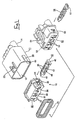
- Figure 1 is a disassembled diagonal view of a waterproof connector of a first embodiment of the present invention.
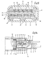
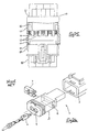
- Figure 2 is a disassembled cross-sectional view of a male housing.
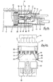
- Figure 3 is a cross-sectional view along the line X-X of Figure 2 showing an inner housing and a retainer.
- Figure 4 is a cross-sectional view along the line Y-Y of Figure 2 showing the inner housing and the retainer.
- Figure 5 is a front view of a female housing.
- Figure 6 is a plan view of the female housing.
- Figure 7 is a cross-sectional view of the female housing.
- Figure 8 is a cross-sectional view along the line Z-Z of Figure 7 showing the retainer in a temporary retaining position.
- Figure 9 is a cross-sectional view along the line Z-Z of Figure 7 showing the retainer in a main retaining position.
- Figure 10 is a cross-sectional view along the line X-X of Figure 2 showing the retainer in the temporary retaining position.
- Figure 11 is a cross-sectional view along the line X-X of Figure 2 showing an inner housing and an outer housing in a fitted state.
- Figure 12 is a cross-sectional view along the line X-X of Figure 2 showing the retainer protruding from a side face of the inner housing.
- Figure 13 is a cross-sectional view along the line X-X of Figure 2 showing the retainer being pushed by the guiding member into the temporary retaining position.
- Figure 14 is a cross-sectional view showing female terminal fittings being inserted into both cavities.
- Figure 15 is a cross-sectional view along the line Y-Y of Figure 2 showing stopping protrusions in a state whereby they are distant from inner cavities.
- Figure 16 is a cross-sectional view showing male terminal fittings being inserted into both cavities.
- Figure 17 is a cross-sectional view along the line X-X of Figure 2 showing the retainer in a state whereby it has been moved into the main retaining position.
- Figure 18 is a cross-sectional view along the line Y-Y of Figure 2 showing the stopping protrusions in a state whereby they have been inserted into the inner cavities.
- Figure 19 is a cross-sectional view of the male terminal fittings retained by the retainer which is in the main retaining position.
- Figure 20 is a partially cut-away plan view showing the male and female housings prior to being fitted together.
- Figure 21 is a partially cut-away plan view showing the male and female housings being fitted together.
- Figure 22 is a partially cut-away plan view showing the male and female housings in a correctly fitted state.
- Figure 23 is a partially cut-away plan view showing male and female housings of the second embodiment of the present invention.
- Figure 24 is a partially cut-away plan view showing a female retainer being pushed into the main retaining position by a second guiding member.
- Figure 25 is a partially cut-away plan view showing male and female housings of the third embodiment of the present invention.
- Figure 26 is a diagonal view of a prior art example.
-
- A first embodiment of the present invention is described below with the aid of Figures 1 to 22. As shown in Figure 1, a waterproof connector is formed from a
male connector housing 10 and a female connector housing 50. Themale housing 10 comprises aninner housing 30 fitting within a cylindricalouter housing 11. - As shown in Figures 1 and 2, the
outer housing 11 has an approximately cylindrical shape and is provided with ahood 12 which is open to the anterior.Terminal housing chambers 14 are formed in the posterior side of theouter housing 11. Theseterminal housing chambers 14 are provided with an upper and lower layer ofouter cavities 13 into which maleterminal fittings 17 can be inserted. The lower layer of the outer cavities has four mutually aligned large chambers, and the upper layer has five mutually aligned small chambers. Thehood 12 is formed so that theinner housing 30 can be fitted therein. As shown in Figure 10, a pair offitting protrusions 15 are formed on innermost sides of inner faces of thehood 12. These fit withfitting members 34 formed on theinner housing 30, thereby maintaining theinner housing 30 in a fitted state with thehood 12. Arubber ring 16 is attached to the immediate anterior of theinner housing 30, this fitting tightly with an inner circumference face of thehood 12. - As shown in Figure 2, the
inner housing 30 is provided with an upper and lower layer ofinner cavities 32, a separatingwall 31 being provided therebetween at an approximately central location relative to the up-down direction of theinner housing 30. As shown in Figure 14, theseinner cavities 32 pass through, at their posterior, to theouter cavities 13 when theinner housing 30 is in a fitted state within theouter housing 11. The maleterminal fittings 17, which have been passed through theouter cavities 13, are housed within theseinner cavities 32. Alance 19, formed on abox member 18 of each male terminal fitting 17, is capable of engaging resiliently with a stoppinggroove 33 formed in an inner face of eachinner cavity 32. Each male terminal fitting 17 is provided with atab 20 and abarrel member 22. Thetab 20 is formed at the anterior side of thebox member 18. Thebarrel member 22 has arubber stopper 21 clamped thereto, an electric wire being attached to thisrubber stopper 21. Therubber stoppers 21 fit tightly with inner circumference faces of theouter cavities 13, thereby waterproofing thecavities - As shown in Figure 3, posterior ends of the side faces of the
inner housing 30 have the pair offitting members 34 formed thereon. Aretainer attachment hole 35, which opens onto both side faces of theinner housing 30, is formed to the anterior of thefitting members 34. Aretainer 40 can be inserted into thisretainer attachment hole 35 from the right side (relative to Figure 3). As shown in Figures 2 and 3, theretainer attachment hole 35 passes through the separatingwall 31 in a width-wise direction thereof, and lower faces of theupper cavities 32 and upper faces of thelower cavities 32 open onto thisretainer attachment hole 35. As shown in Figure 3, atemporary retaining hole 36 and amain retaining hole 37, both being open to the anterior, are formed in a wall portion located towards the anterior side of theretainer attachment hole 35. Thetemporary retaining hole 36 and the main retaininghole 37 are formed in an approximately central location relative to the width-wise direction of the wall portion, and are aligned from right to left relative to Figure 3. A retainingprotrusion 44 of theretainer 40 engages with thetemporary retaining hole 36 or the main retaininghole 37, thereby allowing theretainer 40 to be maintained at either of two separate locations along the width-wise direction of theretainer attachment hole 35. Furthermore, aretainer operating hole 38 is provided to the right (relative to Figure 3) of thetemporary retaining hole 36. A jig or the like can be inserted via thisretainer operating hole 38 in order to operate theretainer 40 within theretainer attachment hole 35. - As shown in Figures 1 and 3, the
retainer 40 is provided with a long and narrow plate-shapedmain body 41. Apressing operating member 42 protrudes towards the anterior from a right edge (relative to Figure 3) of themain body 41. This pressing operatingmember 42 allows a pressing operation while theretainer 40 is attached to theinner housing 30. An arch-shaped bendingmember 43 protrudes from an anterior face of themain body 41 at a location to the left of the pressing operating member 42 (a space remains between the bendingmember 43 and the pressing operating member 42). The retainingprotrusion 44 protrudes from the centre of an anterior face of the bendingmember 43. When theretainer 40 is to be moved within theretainer attachment hole 35, the retainingprotrusion 44 is pressed, thereby bending the centre of the bendingmember 43 in a concave manner (see Figure 12). - As shown in Figure 4, stopping
protrusions 45 protrude from upper and lower faces of themain body 41. Four stoppingprotrusions 45 are formed on the lower face, and five stoppingprotrusions 45 are formed on the upper face, these stoppingprotrusions 45 being formed in locations which correspond to spaces between theinner cavities 32. - The stopping
protrusions 45 engage with the maleterminal fittings 17 which have been inserted into theinner cavities 32. As shown in Figure 10, when theretainer 40 is inside theinner housing 30 and the retainingprotrusion 44 is in a location whereby it engages with thetemporary retaining hole 36, the stoppingprotrusions 45 are distant from the inner cavities 32 (shown in Figure 15). This allows the maleterminal fittings 17 to be inserted into or removed from theinner cavities 32. At this juncture, theretainer 40 is in a temporary retaining position. When theretainer 40 is in this temporary retaining position, an outer side face of thepressing operating member 42 thereof is located so as to form an approximately unified face with a side face of theinner housing 30. - As shown in Figure 17, when the
retainer 40 is inside theinner housing 30 and the retainingprotrusion 44 is in a location whereby it engages with the main retaininghole 37, the stoppingprotrusions 45 come to be located in the inner cavities 32 (see Figure 18) and engage with posterior ends of thebox members 18 of the maleterminal fittings 17. At this juncture, theretainer 40 is in a main retaining position. When theretainer 40 is in this main retaining position, the outer side face of thepressing operating member 42 thereof is located inwards relative to the side face of theinner housing 30. - Next, the
female housing 50 will be explained. As shown in Figure 1, thefemale housing 50 is capable of being fitted within thehood 12 of theouter housing 11. A lockingarm 51 formed on an upper face of thefemale housing 50 is locked by a lockingprotrusion 23 provided on an upper face of theouter housing 11, thereby maintaining thefemale housing 50 in a fitted state with theouter housing 11. An anterior end of thefemale housing 50 is reduced in diameter, having a stepped shape. After thefemale housing 50 has been fitted, therubber ring 16 fits tightly with a circumference face of the reduced diameter portion (see Figure 22). - As shown in Figures 5 and 6, a
rib 52 protrudes outwards from a left side face (relative to Figures 5 and 6) at a posterior end of the reduced diameter portion. Thisrib 52 is provided at an approximately central location, relative to the up-down direction of thefemale housing 50, and extends from an anterior edge of the wider diameter portion to an approximately central location relative to the length-wise direction of thefemale housing 50. An anterior end face of thisrib 52 is tapered. - As shown in Figure 7,
cavities 53 are formed inside thefemale housing 50 at locations which correspond to theinner cavities 32 of themale housing 10. Femaleterminal fittings 54 which have been inserted into thecavities 53 make contact with thetabs 20 of the corresponding maleterminal fittings 17. The femaleterminal fittings 54 have approximately the same configuration as the maleterminal fittings 17, with the difference that they do not havetabs 20. Consequently, a description of the femaleterminal fittings 54 is omitted. Furthermore, the configuration of thecavities 53 is approximately the same as that of the maleinner cavities 32 and of theouter cavities 13, and a description thereof is omitted. - As shown in Figure 1, a
retainer attachment hole 55 opens onto a side face of thefemale housing 50 at the side opposite that provided with therib 52. As is the case with themale housing 10, aretainer 56 can be inserted into thisretainer attachment hole 55. Theretainer 56 has approximately the same configuration as themale retainer 40, and accordingly a description thereof is omitted. As shown in Figure 8, when theretainer 56 is maintained in a temporary retaining position which allows the femaleterminal fittings 54 to be inserted into or removed from thecavities 53, apressing operating member 57 of theretainer 56 protrudes for a specified distance from a side face of thefemale housing 50. - As shown in Figure 9, when the
retainer 56 is maintained in a main retaining position which retains the femaleterminal fittings 54, an outer side face of thepressing operating member 57 forms an approximately unified face with the side face of thefemale housing 50. - As shown in Figure 1, a protruding
member 60 protrudes outwards from thehood 12 of the outer housing 1 of themale housing 10. This protrudingmember 60 is formed at a right side (relative to Figure 1) of thehood 12, at an approximately central location relative to the up-down direction thereof. The protrudingmember 60 extends from the anterior end face of thishood 12 and extends for approximately one third of the entire length thereof. - As shown in Figure 20, a guiding
groove 61, which allows therib 52 of thefemale housing 50 to be inserted, is formed in a concave manner in an inner face of the protrudingmember 60. As shown in Figure 1, this guidinggroove 61 is formed at approximately the same height as therib 52 of thefemale housing 50 and theretainer 40 which is inserted into theinner housing 30. As shown in Figure 12, the guidinggroove 61 allows insertion to take place even if thepressing operating member 42 of theretainer 40 protrudes, to a certain degree, from the side face of theinner housing 30. - A guiding
member 62 joins with the posterior of the guidinggroove 61. This guidingmember 62 forms an inwardly inclining face. The guidingmember 62 has a tapered shape, protruding slightly inwards from a location immediately to the posterior of the guidinggroove 61 to an innermost end of the inner face of the protrudingmember 60. The posterior end thereof joins with a posterior side inner face of thehood 12. An end of thepressing operating member 42 of theretainer 40 which has been inserted into the guidinggroove 61 is capable of making contact with the guidingmember 62, theretainer 40 being pressed inwards by the guidingmember 62 as the insertion operation progresses (see Figure 13). The angle of inclination of the guidingmember 62 corresponds to the angle of inclination of the anterior end face of therib 52 of thefemale housing 50. As shown in Figure 22, the anterior end face of therib 52 makes contact with the guidingmember 62 when thefemale housing 50 has been correctly fitted. When theinner housing 3 is fitted within thehood 12 and therubber ring 16 is in a fitted state, a posterior end of the guidingmember 62 is located in approximately the same location as an anterior face of thisrubber ring 16. - The present embodiment is configured as described above. Next, the order of assembly of the
male housing 10 and the fitting operation of the male andfemale housings retainer 40 is inserted into theinner housing 30 as far as the temporary retaining position, whereby the outer side face of thepressing operating member 42 forms an approximately unified face with a side face of theinner housing 30. Then theinner housing 30 is fitted into thehood 12 of theouter housing 11. Next, as shown in Figure 11, theinner housing 30 is fitted to a depth whereby itsfitting members 34 engage with thefitting protrusions 15 within thehood 12. Then therubber ring 16 is attached to an anterior side of theinner housing 30. - If the
retainer 40 is not inserted to a sufficient depth when it is inserted to this temporary retaining position, thepressing operating member 42 of theretainer 40 protrudes from the side face of the inner housing 30 (shown in Figure 12). If the degree to which theretainer 40 protrudes is sufficient to allow it to be inserted into the guidinggroove 61, and the operator fits theinner housing 30 into theouter housing 11 without noticing that theretainer 40 is protruding, the protruding end of theretainer 40 engages with the guidingmember 62. As shown in Figure 13, the protruding end of theretainer 40 is pushed inwards by the guidingmember 62 while theinner housing 30 is being pushed inwards and, as shown in Figure 11, the side face of thepressing operating member 42 of theretainer 40 forms an approximately unified face with the side face of theinner housing 30. In this manner, the guidingmember 62 automatically moves theretainer 40 into the correct temporary retaining position as the fitting operation of theinner housing 30 progresses. - The
retainer 40, while still being capable of being inserted into the guidinggroove 16, may protrude to such a small extent that it is difficult for the operator to detect visually whether it is protruding prior to the fitting operation. However, as long as theretainer 40 protrudes to the extent that its protruding end makes contact with the anterior end face of thehood 12, the operator can easily detect this protruding state before the fitting operation commences. - As shown in Figure 14, after the
inner housing 30 has been fitted, the maleterminal fittings 17 are inserted into theouter cavities 13 and theinner cavities 32 while these are in a joined state. As shown in Figure 15, theretainer 40 is in the temporary retaining position at this juncture. The stoppingprotrusions 45 are distant from theinner cavities 32 and, as shown in Figure 16, the maleterminal fittings 17 can be inserted as far as a position in which thelances 19 engage with the stoppinggrooves 33. After the maleterminal fittings 17 have been inserted, a jig or the like is inserted into theretainer operating hole 38 from the anterior of thehood 12, and the side face of the bendingmember 43 is pressed, thereby moving theretainer 40 into the main retaining position (see Figure 17). By this means, the stoppingprotrusions 45 engage with the posterior ends of thebox members 18, thereby doubly retaining the male terminal fittings 17 (see Figures 18 and 19). - After the
male housing 10 has been assembled in this manner, thefemale housing 50 is fitted into the hood 12 (see Figure 20). As shown in Figure 21, therib 52 is inserted into the guidinggroove 61 as the male andfemale housings female housing 50 makes contact with the anterior face of therubber ring 16, the lockingarm 51 is locked by the lockingprotrusion 23, thereby maintaining the male andfemale housings - According to the embodiment described above, the guiding
member 62 automatically pushes the protrudingretainer 40 into the correct temporary retaining position while the fitting operation of theinner housing 20 progresses. As a result,retainers 40 which protrude do not need to be moved individually, and the operation can be performed smoothly. Furthermore, the guidingmember 62 is provided immediately inwards from the guidinggroove 61. Consequently, the parts for correcting the movement of theretainer 40 and the parts for guiding the fitting operation of the male andfemale housings - The
male housing 10 is divided into theouter housing 11 and theinner housing 30. As a result, the opening into which theretainer 40 is inserted does not open onto the exterior. - A second embodiment of the present invention is now described below with the aid of Figures 8, 9, 23 and 24. The second embodiment describes a means to correct the movement of the retainer attached to the female housing which is fitted within the male housing.
- As shown in Figure 23, a protruding
member 70 protrudes outwards from ahood 12 of anouter housing 11 of amale housing 10. This protrudingmember 70 is formed at a left side (relative to Figure 23) of thehood 12. That is, it is formed at the same side as aretainer attachment hole 55 into which aretainer 56 of a female housing 50 (which is fitted into the hood 12) is inserted. A guidingmember 71 is formed on an inner face of the protrudingmember 70. This guidingmember 71 forms an inwardly inclining face. The guidingmember 71 is formed at approximately the same height as theretainer 56 which is inserted into theretainer attachment hole 55 of thefemale housing 50. The guidingmember 71 is capable of making contact with theretainer 56 even if thisretainer 56 protrudes from the side face of thefemale housing 50. - Prior to the male and
female housings retainer 56 is inserted to a temporary retaining position in theretainer attachment hole 55 of thefemale housing 50, apressing operating member 57 protruding from the side face of the female housing 50 (see Figure 8). In this state, femaleterminal fittings 54 are inserted intocavities 53. Then theretainer 56 is moved to a main retaining position, in which the outer side face of thepressing operating member 57 of theretainer 56 forms an approximately unified face with the side face of the female housing 50 (see Figure 9), thereby doubly retaining the femaleterminal fittings 54. - In the second embodiment, the main retaining position of the
female retainer 56 corresponds to the correct attachment permitting position of the Claims. - If the
retainer 56 is not inserted to a sufficient depth when it is moved to the main retaining position, thepressing operating member 57 of theretainer 56 may protrude from the side face of the female housing 50 (see Figure 23). If the male andfemale housings pressing operating member 57 of theretainer 56 engages with the guidingmember 71, and this guidingmember 71 pushes theretainer 56 inwards as the fitting progresses (see Figure 24). By this means, theretainer 56 can automatically be moved into the correct main retaining position as the male andfemale housings - The length of the guiding
member 71 in the direction of fitting is such that it is capable of moving theretainer 56 into the main retaining position before the male and femaleterminal fittings terminal fittings 54 make contact with the maleterminal fittings 17 in a state whereby they are doubly retained, and are reliably prevented from being removed. - A third embodiment of the present invention is now described below with the aid of Figure 25. The third embodiment shows a guiding member having a different shape from that of the second embodiment.
- As shown in Figure 25, a guiding
member 72 is formed on the anterior inner face of ahood 12 of anouter hosing 11. This guidingmember 72 is an inwardly inclining face. The guidingmember 72 is formed on the left side (relative to Figure 25) of thehood 12. That is, it is formed on the same side as aretainer attachment hole 55 of afemale housing 50. The guidingmember 72 is formed at approximately the same height as aretainer 56 which is inserted into theretainer attachment hole 55. - The guiding
member 72 is formed in a tapered shape at the anterior inner face of thehood 12. Consequently, the configuration of the connector is simplified. Moreover, the configuration of the other parts, and their operation and effects, is the same as in the second embodiment, and a description thereof is omitted. - The present invention is not limited to the embodiments described above with the aid of figures. For example, the possibilities described below also lie within the technical range of the present invention. In addition, the present invention may be embodied in various other ways without deviating from the scope thereof.
- (1) The second and third embodiments have described a means for moving a retainer into a correct position while male and female connector housings are fitted together. However, the present invention is equally suitable for use in a male connector housing which is not divided into two.
- (2) As a specific example of(1) above, one of the connector housings may be provided with a guiding member and a guiding groove, and the other connector housing with a rib. Accordingly, the retainer may be moved into the correct position by the guiding member while it is being fitted with the other connector housing, and the rib may be inserted into the guiding groove to guide the fitting operation.
- (3) The above embodiment describes a waterproof connector. However,. the present invention is also suitable for other types of connectors.
-
Claims (9)
- An electrical connector comprising three parts: a terminal retaining body (30) having cavities (32) to receive electrical terminals (17); a retainer (40) insertable into said terminal retaining body (30) from a protruding to a non-protruding condition and adapted to retain electrical terminals therein; and a tubular housing (11) to receive the terminal retaining body (30) and retainer (40) therein; wherein a first guiding member (62) is provided on the inner face of said tubular housing (11), the first guiding member (62) being adapted to engage said retainer (40) in a protruding condition, and to urge said retainer (40) to a non-protruding condition as the terminal retaining body (30) is received within said tubular housing (11); wherein said first guiding member comprises a tapered face (62) for engagement with said retainer (40), said tapered face (62) being directed inwardly of the housing with respect to the direction of insertion; characterised in that said tubular housing includes a guiding groove (61) in its inner face of said tubular housing, the guiding groove (61) guiding a protruding retainer (40) to said tapered face (62).
- An electrical connector according to claim 1, and a mating connector (50), the mating connector (50) being receivable in said tubular housing (11), and having a protrusion (52) engageable in said guiding groove (61).
- An electrical connector according to claim 2 wherein said mating connector (50) includes a retainer (56) insertable therein from a protruding to a non-protruding condition, and said tubular housing (11) further includes a second guiding member (71, 72) on the inner face thereof, adapted to engage the retainer (56) of said mating connector (50), and to urge that retainer (56) to a non-protruding condition as the mating connector (50) is received within said tubular housing (11).
- An electrical connector according to claim 3 wherein said second guiding member comprises a tapered face (71, 72).
- An electrical connector according to claim 4 wherein said first and second guiding members (62; 71, 72) are opposite each other on said tubular housing (11).
- An electrical connector according to any preceding claim wherein the retainer (40) of said terminal retaining body (30) is latchable in said body (30) in a non-protruding condition.
- An electrical connector according to any of claims 3-5 wherein the retainer (56) of said mating connector (50) is latchable in said body (50) in protruding and non-protruding conditions.
- An electrical connector according to claim 7 wherein said mating connector (50) is latchable in said tubular housing (11).
- A connector according to any preceding claim wherein said retainer (40) of said terminal retaining body (30) is further movable from a non-protruding temporary state to a non-protruding final state, electrical terminals being insertable into said body (30) in the non-protruding temporary state of said retainer (40), and being latched with respect to said body in the non protruding final state of said retainer (40).
Applications Claiming Priority (2)
| Application Number | Priority Date | Filing Date | Title |
|---|---|---|---|
| JP35303399A JP3463636B2 (en) | 1999-12-13 | 1999-12-13 | connector |
| JP35303399 | 1999-12-13 |
Publications (3)
| Publication Number | Publication Date |
|---|---|
| EP1109263A2 EP1109263A2 (en) | 2001-06-20 |
| EP1109263A3 EP1109263A3 (en) | 2003-03-26 |
| EP1109263B1 true EP1109263B1 (en) | 2005-03-02 |
Family
ID=18428122
Family Applications (1)
| Application Number | Title | Priority Date | Filing Date |
|---|---|---|---|
| EP00310468A Expired - Lifetime EP1109263B1 (en) | 1999-12-13 | 2000-11-24 | Electrical connector |
Country Status (4)
| Country | Link |
|---|---|
| US (1) | US6358102B1 (en) |
| EP (1) | EP1109263B1 (en) |
| JP (1) | JP3463636B2 (en) |
| DE (1) | DE60018363T2 (en) |
Families Citing this family (25)
| Publication number | Priority date | Publication date | Assignee | Title |
|---|---|---|---|---|
| ES1044530Y (en) * | 1999-11-10 | 2000-09-01 | Mecanismos Aux Ind | LOCKING ELEMENT FOR ELECTRICAL CONNECTOR ASSEMBLY. |
| DE10017868B4 (en) * | 2000-04-11 | 2004-03-04 | Leopold Kostal Gmbh & Co. Kg | Electrical connector part |
| JP2002100433A (en) * | 2000-07-17 | 2002-04-05 | Yazaki Corp | Connector with retainer |
| JP4103333B2 (en) * | 2000-12-28 | 2008-06-18 | 住友電装株式会社 | Connector and continuity inspection method in connector |
| JP4349186B2 (en) * | 2004-04-14 | 2009-10-21 | 住友電装株式会社 | connector |
| ITMI20050347A1 (en) * | 2005-03-07 | 2006-09-08 | Ilme Spa | ELECTRIC CONNECTOR ELEMENT FOR CONDUCTORS WITH CRIMPED CONTACTS |
| JP4730237B2 (en) * | 2006-07-20 | 2011-07-20 | 住友電装株式会社 | connector |
| JP4716128B2 (en) * | 2006-09-04 | 2011-07-06 | 住友電装株式会社 | connector |
| EP2325950B1 (en) * | 2007-10-19 | 2014-07-23 | Sumitomo Wiring Systems, Ltd. | A connector |
| JP4636072B2 (en) * | 2007-10-19 | 2011-02-23 | 住友電装株式会社 | connector |
| JP5125408B2 (en) * | 2007-10-26 | 2013-01-23 | 住友電装株式会社 | connector |
| JP5327547B2 (en) * | 2010-01-22 | 2013-10-30 | 住友電装株式会社 | connector |
| US8419485B2 (en) * | 2011-01-27 | 2013-04-16 | Tyco Electronics Corporation | Bulkhead connector assembly |
| KR20160066182A (en) * | 2014-12-02 | 2016-06-10 | 현대자동차주식회사 | Joint connetor |
| JP6535177B2 (en) * | 2015-02-16 | 2019-06-26 | 矢崎総業株式会社 | connector |
| JP5900684B1 (en) * | 2015-04-28 | 2016-04-06 | 第一精工株式会社 | Electrical connector |
| JP6602105B2 (en) * | 2015-08-24 | 2019-11-06 | 矢崎総業株式会社 | connector |
| JP6198793B2 (en) * | 2015-09-16 | 2017-09-20 | 矢崎総業株式会社 | connector |
| JP6944931B2 (en) * | 2016-05-18 | 2021-10-06 | 日本端子株式会社 | connector |
| DE102016217456B3 (en) * | 2016-09-13 | 2017-12-21 | Te Connectivity Germany Gmbh | Arrangement for an electrical connector and plug connector with a contact housing, housing and securing element |
| FR3088491B1 (en) * | 2018-11-12 | 2021-12-03 | Raydiall | CONNECTOR BOX EQUIPPED WITH AN IMPROVED CABLE TERMINAL POSITION ASSURANCE (TPA) DEVICE |
| CN110212357B (en) * | 2018-12-05 | 2021-03-23 | 中航光电科技股份有限公司 | Connector and contact locking piece thereof |
| US10892579B2 (en) * | 2019-02-25 | 2021-01-12 | J.S.T. Corporation | Female terminal position assurance (TPA) device for a connector and method for assembling thereof |
| EP3931912A4 (en) | 2019-02-25 | 2023-02-22 | J.S.T. Corporation | Method for improving clearance and creepage in a high voltage connector assembly using a male or female terminal position assurance (tpa) device |
| CN118266135A (en) | 2021-12-03 | 2024-06-28 | 日本端子株式会社 | Electric connector and pair of electric connectors |
Family Cites Families (12)
| Publication number | Priority date | Publication date | Assignee | Title |
|---|---|---|---|---|
| JP2503320B2 (en) * | 1991-04-04 | 1996-06-05 | 矢崎総業株式会社 | Connector with dual locking mechanism |
| JP2813717B2 (en) * | 1993-04-28 | 1998-10-22 | 矢崎総業株式会社 | Shield connector |
| JPH07211381A (en) * | 1994-01-19 | 1995-08-11 | Yazaki Corp | Locking method and structure for double locking connector |
| JP3120725B2 (en) * | 1996-03-13 | 2000-12-25 | 住友電装株式会社 | Connector with retainer |
| JP3211672B2 (en) * | 1996-07-11 | 2001-09-25 | 住友電装株式会社 | connector |
| US5830013A (en) * | 1997-03-07 | 1998-11-03 | Yazaki Corporation | Electric connector |
| JP3632811B2 (en) | 1997-09-17 | 2005-03-23 | 住友電装株式会社 | Connector with retainer |
| DE69820556T2 (en) * | 1997-09-17 | 2004-09-23 | Sumitomo Wiring Systems, Ltd., Yokkaichi | Connector with holding device |
| US5890935A (en) * | 1997-12-10 | 1999-04-06 | Molex Incorporated | Electrical connector with terminal position assurance device |
| JP3266095B2 (en) * | 1998-03-27 | 2002-03-18 | 住友電装株式会社 | connector |
| US5928038A (en) * | 1998-04-24 | 1999-07-27 | Molex Incorporated | Electrical connector position assurance system |
| JP3864592B2 (en) * | 1998-12-09 | 2007-01-10 | 住友電装株式会社 | Waterproof connector |
-
1999
- 1999-12-13 JP JP35303399A patent/JP3463636B2/en not_active Expired - Fee Related
-
2000
- 2000-11-24 DE DE60018363T patent/DE60018363T2/en not_active Expired - Fee Related
- 2000-11-24 EP EP00310468A patent/EP1109263B1/en not_active Expired - Lifetime
- 2000-12-12 US US09/734,182 patent/US6358102B1/en not_active Expired - Fee Related
Also Published As
| Publication number | Publication date |
|---|---|
| US6358102B1 (en) | 2002-03-19 |
| EP1109263A3 (en) | 2003-03-26 |
| EP1109263A2 (en) | 2001-06-20 |
| DE60018363T2 (en) | 2005-12-29 |
| JP2001167835A (en) | 2001-06-22 |
| JP3463636B2 (en) | 2003-11-05 |
| DE60018363D1 (en) | 2005-04-07 |
Similar Documents
| Publication | Publication Date | Title |
|---|---|---|
| EP1109263B1 (en) | Electrical connector | |
| EP1020958B1 (en) | Connector | |
| EP1187265B1 (en) | Waterproof connector | |
| US4902247A (en) | Electrical connector | |
| US7476133B2 (en) | Connector | |
| US6413105B2 (en) | Lever-type connector | |
| US20020009922A1 (en) | Waterproof connector with sealing member | |
| US9673563B2 (en) | Connector | |
| EP0955697A1 (en) | A waterproof connector | |
| US6655998B1 (en) | Connector | |
| US6575788B2 (en) | Connector | |
| US6659811B2 (en) | Connector | |
| US6520788B2 (en) | Watertight connector and sealing member | |
| EP1049214A1 (en) | Connector | |
| EP1009065B1 (en) | Waterproof connector | |
| EP1033788B1 (en) | Connector with secondary locking | |
| US6461177B1 (en) | Electrical connector | |
| JPH0495368A (en) | Connector with terminal fixture | |
| US6368164B1 (en) | Connector with a retainer | |
| US20010012717A1 (en) | Connector | |
| EP1204171B1 (en) | Electrical connector | |
| EP1204170B1 (en) | Electrical connector | |
| US5588875A (en) | Connector |
Legal Events
| Date | Code | Title | Description |
|---|---|---|---|
| PUAI | Public reference made under article 153(3) epc to a published international application that has entered the european phase |
Free format text: ORIGINAL CODE: 0009012 |
|
| 17P | Request for examination filed |
Effective date: 20001215 |
|
| AK | Designated contracting states |
Kind code of ref document: A2 Designated state(s): AT BE CH CY DE DK ES FI FR GB GR IE IT LI LU MC NL PT SE TR |
|
| AX | Request for extension of the european patent |
Free format text: AL;LT;LV;MK;RO;SI |
|
| PUAL | Search report despatched |
Free format text: ORIGINAL CODE: 0009013 |
|
| AK | Designated contracting states |
Designated state(s): AT BE CH CY DE DK ES FI FR GB GR IE IT LI LU MC NL PT SE TR Kind code of ref document: A3 Designated state(s): AT BE CH CY DE DK ES FI FR GB GR IE IT LI LU MC NL PT SE TR |
|
| AX | Request for extension of the european patent |
Extension state: AL LT LV MK RO SI |
|
| AKX | Designation fees paid |
Designated state(s): DE FR GB IT |
|
| 17Q | First examination report despatched |
Effective date: 20040305 |
|
| GRAP | Despatch of communication of intention to grant a patent |
Free format text: ORIGINAL CODE: EPIDOSNIGR1 |
|
| GRAS | Grant fee paid |
Free format text: ORIGINAL CODE: EPIDOSNIGR3 |
|
| GRAA | (expected) grant |
Free format text: ORIGINAL CODE: 0009210 |
|
| AK | Designated contracting states |
Kind code of ref document: B1 Designated state(s): DE FR GB IT |
|
| PG25 | Lapsed in a contracting state [announced via postgrant information from national office to epo] |
Ref country code: IT Free format text: LAPSE BECAUSE OF FAILURE TO SUBMIT A TRANSLATION OF THE DESCRIPTION OR TO PAY THE FEE WITHIN THE PRESCRIBED TIME-LIMIT;WARNING: LAPSES OF ITALIAN PATENTS WITH EFFECTIVE DATE BEFORE 2007 MAY HAVE OCCURRED AT ANY TIME BEFORE 2007. THE CORRECT EFFECTIVE DATE MAY BE DIFFERENT FROM THE ONE RECORDED. Effective date: 20050302 |
|
| REG | Reference to a national code |
Ref country code: GB Ref legal event code: FG4D |
|
| REG | Reference to a national code |
Ref country code: IE Ref legal event code: FG4D |
|
| REF | Corresponds to: |
Ref document number: 60018363 Country of ref document: DE Date of ref document: 20050407 Kind code of ref document: P |
|
| PG25 | Lapsed in a contracting state [announced via postgrant information from national office to epo] |
Ref country code: GB Free format text: LAPSE BECAUSE OF NON-PAYMENT OF DUE FEES Effective date: 20051124 |
|
| ET | Fr: translation filed | ||
| PLBE | No opposition filed within time limit |
Free format text: ORIGINAL CODE: 0009261 |
|
| STAA | Information on the status of an ep patent application or granted ep patent |
Free format text: STATUS: NO OPPOSITION FILED WITHIN TIME LIMIT |
|
| 26N | No opposition filed |
Effective date: 20051205 |
|
| GBPC | Gb: european patent ceased through non-payment of renewal fee |
Effective date: 20051124 |
|
| PGFP | Annual fee paid to national office [announced via postgrant information from national office to epo] |
Ref country code: DE Payment date: 20071122 Year of fee payment: 8 |
|
| PGFP | Annual fee paid to national office [announced via postgrant information from national office to epo] |
Ref country code: FR Payment date: 20071108 Year of fee payment: 8 |
|
| REG | Reference to a national code |
Ref country code: FR Ref legal event code: ST Effective date: 20090731 |
|
| PG25 | Lapsed in a contracting state [announced via postgrant information from national office to epo] |
Ref country code: DE Free format text: LAPSE BECAUSE OF NON-PAYMENT OF DUE FEES Effective date: 20090603 |
|
| PG25 | Lapsed in a contracting state [announced via postgrant information from national office to epo] |
Ref country code: FR Free format text: LAPSE BECAUSE OF NON-PAYMENT OF DUE FEES Effective date: 20081130 |