EP1109035A2 - Reflecting mirror and rear projection display making use thereof - Google Patents
Reflecting mirror and rear projection display making use thereof Download PDFInfo
- Publication number
- EP1109035A2 EP1109035A2 EP00311321A EP00311321A EP1109035A2 EP 1109035 A2 EP1109035 A2 EP 1109035A2 EP 00311321 A EP00311321 A EP 00311321A EP 00311321 A EP00311321 A EP 00311321A EP 1109035 A2 EP1109035 A2 EP 1109035A2
- Authority
- EP
- European Patent Office
- Prior art keywords
- reflecting mirror
- glass substrate
- rear projection
- projection display
- film
- Prior art date
- Legal status (The legal status is an assumption and is not a legal conclusion. Google has not performed a legal analysis and makes no representation as to the accuracy of the status listed.)
- Withdrawn
Links
- 239000011521 glass Substances 0.000 claims abstract description 29
- 239000000758 substrate Substances 0.000 claims abstract description 29
- 238000005259 measurement Methods 0.000 claims abstract description 15
- XAGFODPZIPBFFR-UHFFFAOYSA-N aluminium Chemical compound [Al] XAGFODPZIPBFFR-UHFFFAOYSA-N 0.000 claims abstract description 7
- 229910052782 aluminium Inorganic materials 0.000 claims abstract description 7
- GWEVSGVZZGPLCZ-UHFFFAOYSA-N Titan oxide Chemical compound O=[Ti]=O GWEVSGVZZGPLCZ-UHFFFAOYSA-N 0.000 claims abstract description 6
- ORUIBWPALBXDOA-UHFFFAOYSA-L magnesium fluoride Chemical compound [F-].[F-].[Mg+2] ORUIBWPALBXDOA-UHFFFAOYSA-L 0.000 claims abstract description 5
- 238000006124 Pilkington process Methods 0.000 claims description 14
- 230000003287 optical effect Effects 0.000 claims description 5
- 238000005498 polishing Methods 0.000 description 9
- 238000000034 method Methods 0.000 description 6
- KWYUFKZDYYNOTN-UHFFFAOYSA-M Potassium hydroxide Chemical compound [OH-].[K+] KWYUFKZDYYNOTN-UHFFFAOYSA-M 0.000 description 3
- 239000004973 liquid crystal related substance Substances 0.000 description 3
- 238000004140 cleaning Methods 0.000 description 2
- 238000001704 evaporation Methods 0.000 description 2
- 238000004519 manufacturing process Methods 0.000 description 2
- 239000000463 material Substances 0.000 description 2
- 238000004544 sputter deposition Methods 0.000 description 2
- 238000004506 ultrasonic cleaning Methods 0.000 description 2
- XLYOFNOQVPJJNP-UHFFFAOYSA-N water Substances O XLYOFNOQVPJJNP-UHFFFAOYSA-N 0.000 description 2
- 206010052128 Glare Diseases 0.000 description 1
- 239000003082 abrasive agent Substances 0.000 description 1
- 229910000420 cerium oxide Inorganic materials 0.000 description 1
- 239000012459 cleaning agent Substances 0.000 description 1
- 230000006866 deterioration Effects 0.000 description 1
- 238000010586 diagram Methods 0.000 description 1
- 238000009792 diffusion process Methods 0.000 description 1
- 230000008020 evaporation Effects 0.000 description 1
- 230000004313 glare Effects 0.000 description 1
- 229910001635 magnesium fluoride Inorganic materials 0.000 description 1
- BMMGVYCKOGBVEV-UHFFFAOYSA-N oxo(oxoceriooxy)cerium Chemical compound [Ce]=O.O=[Ce]=O BMMGVYCKOGBVEV-UHFFFAOYSA-N 0.000 description 1
- 238000007517 polishing process Methods 0.000 description 1
- 238000004439 roughness measurement Methods 0.000 description 1
- 230000003746 surface roughness Effects 0.000 description 1
- 239000004408 titanium dioxide Substances 0.000 description 1
- 238000007738 vacuum evaporation Methods 0.000 description 1
- 238000005406 washing Methods 0.000 description 1
Images


Classifications
-
- G—PHYSICS
- G02—OPTICS
- G02B—OPTICAL ELEMENTS, SYSTEMS OR APPARATUS
- G02B5/00—Optical elements other than lenses
- G02B5/08—Mirrors
- G02B5/0816—Multilayer mirrors, i.e. having two or more reflecting layers
- G02B5/085—Multilayer mirrors, i.e. having two or more reflecting layers at least one of the reflecting layers comprising metal
- G02B5/0858—Multilayer mirrors, i.e. having two or more reflecting layers at least one of the reflecting layers comprising metal the reflecting layers comprising a single metallic layer with one or more dielectric layers
-
- C—CHEMISTRY; METALLURGY
- C03—GLASS; MINERAL OR SLAG WOOL
- C03C—CHEMICAL COMPOSITION OF GLASSES, GLAZES OR VITREOUS ENAMELS; SURFACE TREATMENT OF GLASS; SURFACE TREATMENT OF FIBRES OR FILAMENTS MADE FROM GLASS, MINERALS OR SLAGS; JOINING GLASS TO GLASS OR OTHER MATERIALS
- C03C17/00—Surface treatment of glass, not in the form of fibres or filaments, by coating
- C03C17/34—Surface treatment of glass, not in the form of fibres or filaments, by coating with at least two coatings having different compositions
- C03C17/36—Surface treatment of glass, not in the form of fibres or filaments, by coating with at least two coatings having different compositions at least one coating being a metal
-
- C—CHEMISTRY; METALLURGY
- C03—GLASS; MINERAL OR SLAG WOOL
- C03C—CHEMICAL COMPOSITION OF GLASSES, GLAZES OR VITREOUS ENAMELS; SURFACE TREATMENT OF GLASS; SURFACE TREATMENT OF FIBRES OR FILAMENTS MADE FROM GLASS, MINERALS OR SLAGS; JOINING GLASS TO GLASS OR OTHER MATERIALS
- C03C17/00—Surface treatment of glass, not in the form of fibres or filaments, by coating
- C03C17/34—Surface treatment of glass, not in the form of fibres or filaments, by coating with at least two coatings having different compositions
- C03C17/36—Surface treatment of glass, not in the form of fibres or filaments, by coating with at least two coatings having different compositions at least one coating being a metal
- C03C17/3602—Surface treatment of glass, not in the form of fibres or filaments, by coating with at least two coatings having different compositions at least one coating being a metal the metal being present as a layer
- C03C17/3615—Coatings of the type glass/metal/other inorganic layers, at least one layer being non-metallic
-
- C—CHEMISTRY; METALLURGY
- C03—GLASS; MINERAL OR SLAG WOOL
- C03C—CHEMICAL COMPOSITION OF GLASSES, GLAZES OR VITREOUS ENAMELS; SURFACE TREATMENT OF GLASS; SURFACE TREATMENT OF FIBRES OR FILAMENTS MADE FROM GLASS, MINERALS OR SLAGS; JOINING GLASS TO GLASS OR OTHER MATERIALS
- C03C17/00—Surface treatment of glass, not in the form of fibres or filaments, by coating
- C03C17/34—Surface treatment of glass, not in the form of fibres or filaments, by coating with at least two coatings having different compositions
- C03C17/36—Surface treatment of glass, not in the form of fibres or filaments, by coating with at least two coatings having different compositions at least one coating being a metal
- C03C17/3602—Surface treatment of glass, not in the form of fibres or filaments, by coating with at least two coatings having different compositions at least one coating being a metal the metal being present as a layer
- C03C17/3621—Surface treatment of glass, not in the form of fibres or filaments, by coating with at least two coatings having different compositions at least one coating being a metal the metal being present as a layer one layer at least containing a fluoride
-
- C—CHEMISTRY; METALLURGY
- C03—GLASS; MINERAL OR SLAG WOOL
- C03C—CHEMICAL COMPOSITION OF GLASSES, GLAZES OR VITREOUS ENAMELS; SURFACE TREATMENT OF GLASS; SURFACE TREATMENT OF FIBRES OR FILAMENTS MADE FROM GLASS, MINERALS OR SLAGS; JOINING GLASS TO GLASS OR OTHER MATERIALS
- C03C17/00—Surface treatment of glass, not in the form of fibres or filaments, by coating
- C03C17/34—Surface treatment of glass, not in the form of fibres or filaments, by coating with at least two coatings having different compositions
- C03C17/36—Surface treatment of glass, not in the form of fibres or filaments, by coating with at least two coatings having different compositions at least one coating being a metal
- C03C17/3602—Surface treatment of glass, not in the form of fibres or filaments, by coating with at least two coatings having different compositions at least one coating being a metal the metal being present as a layer
- C03C17/3657—Surface treatment of glass, not in the form of fibres or filaments, by coating with at least two coatings having different compositions at least one coating being a metal the metal being present as a layer the multilayer coating having optical properties
- C03C17/3663—Surface treatment of glass, not in the form of fibres or filaments, by coating with at least two coatings having different compositions at least one coating being a metal the metal being present as a layer the multilayer coating having optical properties specially adapted for use as mirrors
-
- G—PHYSICS
- G02—OPTICS
- G02B—OPTICAL ELEMENTS, SYSTEMS OR APPARATUS
- G02B5/00—Optical elements other than lenses
- G02B5/08—Mirrors
- G02B5/0808—Mirrors having a single reflecting layer
-
- G—PHYSICS
- G03—PHOTOGRAPHY; CINEMATOGRAPHY; ANALOGOUS TECHNIQUES USING WAVES OTHER THAN OPTICAL WAVES; ELECTROGRAPHY; HOLOGRAPHY
- G03B—APPARATUS OR ARRANGEMENTS FOR TAKING PHOTOGRAPHS OR FOR PROJECTING OR VIEWING THEM; APPARATUS OR ARRANGEMENTS EMPLOYING ANALOGOUS TECHNIQUES USING WAVES OTHER THAN OPTICAL WAVES; ACCESSORIES THEREFOR
- G03B21/00—Projectors or projection-type viewers; Accessories therefor
- G03B21/14—Details
- G03B21/28—Reflectors in projection beam
-
- C—CHEMISTRY; METALLURGY
- C03—GLASS; MINERAL OR SLAG WOOL
- C03C—CHEMICAL COMPOSITION OF GLASSES, GLAZES OR VITREOUS ENAMELS; SURFACE TREATMENT OF GLASS; SURFACE TREATMENT OF FIBRES OR FILAMENTS MADE FROM GLASS, MINERALS OR SLAGS; JOINING GLASS TO GLASS OR OTHER MATERIALS
- C03C2218/00—Methods for coating glass
- C03C2218/30—Aspects of methods for coating glass not covered above
- C03C2218/31—Pre-treatment
Definitions
- the present invention relates to a reflecting mirror for use in a display device by which an image to be displayed is enlarged and reflected on a mirror and thereby is projected on a screen, such as that of a rear projection television, and the invention relates to a rear projection display making use thereof.
- a reflecting film of aluminum is formed by an evaporation method or a sputtering method. Also, a glass substrate which is produced by a float process is normally used.
- microcorrugations (around 0.1 ⁇ m - 0.16 ⁇ m on the measurement condition that the cut-off value is 0.8 mm to 8 mm) occur parallel to the transfer direction of the float process in the course of the production.
- Such irregularities inevitably occur on a surface of the glass substrate due to the production process of the glass substrate.
- a reflecting mirror for use in a rear projection display and so on, comprising a glass substrate at least one surface of which is polished to have a predetermined surface waviness, and a reflecting film which is formed on the polished surface of the glass substrate.
- the glass substrate is produced by a float process to have minute irregularities of 0.1 ⁇ m or less on the measurement condition that the cut-off value is 0.8mm to 8 mm.
- the predetermined surface waviness is 0.05 ⁇ m or less on the measurement condition that the cut-off value is 0.8 mm to 8 mm.
- the reflecting film is obtained by film-forming in the order of aluminum (Al), magnesium fluoride (MgF 2 ) and titanium dioxide (TiO 2 ). Formed by this method, it is possible that the reflecting mirror has a reflectance of 94%, while a reflecting mirror formed only of aluminum has a lesser reflectance of 88-90%.
- a rear projection display comprising the reflecting mirror mentioned above, an optical unit, and a screen.
- a glass substrate which is produced by a float process to have a thickness of 3 mm, is cut to be a predetermined size, and thereafter the end surface thereof is chamfered. It is preferable that minute irregularities on the surface of the glass substrate are equal to or less than 0.1 ⁇ m on the measurement condition that the cut-off value is 0.8 mm to 8 mm, taking a surface waviness required for a subsequent polishing process into consideration.
- the surface of the glass substrate is removed by around 3 ⁇ m and minute irregularities thereon are reduced, and thereby the surface waviness thereof is made to be of a predetermined value.
- the predetermined surface waviness is equal to or less than 0.05 ⁇ m on the measurement condition that the cut-off value is 0.8 mm to 8 mm measured, for example, using the SURFCOM 479A manufactured by Tokyo Seimitsu Co., Ltd. as a surface roughness measurement apparatus, taking an image quality required in a case where the reflecting mirror is applied as a mirror of a rear projection display into consideration.
- the predetermined surface waviness is equal to or less than 0.001 ⁇ m on the measurement condition that the cut-off value is 0.8 mm to 8 mm, it takes a longer period of time to carry out the polishing and the cost of producing such a reflecting mirror consequently increases.
- the polished glass substrate is immersed in alkaline cleaning agent including potassium hydroxide and is cleaned with an ultrasonic washing machine, Thereafter, an ultrasonic cleaning with pure water is conducted upon the surface of the glass substrate, thereby making the surface clean.
- alkaline cleaning agent including potassium hydroxide
- an ultrasonic cleaning with pure water is conducted upon the surface of the glass substrate, thereby making the surface clean.
- a well-known method such as a brush cleaning can he used as well as the ultrasonic cleaning.
- a reflecting film 2 is formed by sequential film-forming in the order of aluminum (Al), magnesium fluoride (MgF 2 ) and titanium dioxide (TiO 2 ) by a vacuum evaporation on one surface la of the cleaned glass substrate 1, and thereby a reflecting mirror 3 is obtained.
- the thicknesses of the Al film, the MgF 2 film and the TiO 2 film are respectively within the range of 50 nm to 300 nm.
- the light reflected on the reflecting film 2 is prevented from going in different directions by forming the reflecting film 2 after the one surface la of the glass substrate 1 is polished.
- the above-mentioned reflecting mirror 3 is installed.
- the rear projection display comprises the reflecting mirror 3, an optical unit 4, a screen 5 and so on.
- the distance between the reflecting mirror 3 and the screen 5 is typically within a range of 20-70 cm.
- the optical unit 4 comprises a high-brightness discharge lamp, three sheets of liquid crystal panel each of which corresponds to R (Red), G (Green) and B (Blue), a color filter and a projection lens being of a high caliber.
- the screen 5 comprises a Fresnel lens, a lenticular to which a non-glare treatment is applied, and so on.
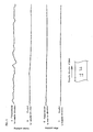
- Fig. 3 shows the results of measurement of the irregularities on the surface of the glass substrate before and after polishing.
- A shows a graph of data of the measurement taken on an axis perpendicular to the transfer direction of the float process before polishing.
- B shows a graph of data of the measurement taken on an axis parallel to the transfer direction of the float process before polishing.
- C shows a graph of data of the measurement taken on an axis perpendicular to the transfer direction of the float process after polishing.
- D shows a graph of data of the measurement taken on an axis parallel to the transfer direction of the float process after polishing.
- the reflecting mirror 3 a back-surface-coated mirror can be used as well as the front-surface-coated mirror shown in Fig. 1.
- the reflecting film can be formed of another material or materials to achieve a reflectance adequate to utilize an image reflected thereby, which is not limited to the aluminum reflecting mirror.
- another method can be used instead of the evaporation or sputtering film-forming method.
- the reflecting mirror 3 according to the present invention can be applied to a rear projection display in which one sheet of liquid crystal panel is used by hologram color filter (film of diffraction grating) as well as a rear projection display which requires three sheets of liquid crystal panel each of which corresponds to R (Red), G (Green) and B (Blue).
- the present invention it is possible to reflect parallel light, which is incident on the reflecting mirror, at a reflection angle equal to the incident angle, and thereby the reflected light is prevented from going in different directions.
- the reflecting mirror is applied as a mirror of a rear projection display.
- the present invention it is possible to sufficiently achieve image quality required in a case where the reflecting mirror is applied as a mirror of the rear projection display, even if the distance between the reflecting mirror and the screen is increased.
Landscapes
- Chemical & Material Sciences (AREA)
- Physics & Mathematics (AREA)
- Materials Engineering (AREA)
- Chemical Kinetics & Catalysis (AREA)
- General Chemical & Material Sciences (AREA)
- Geochemistry & Mineralogy (AREA)
- Life Sciences & Earth Sciences (AREA)
- Organic Chemistry (AREA)
- Engineering & Computer Science (AREA)
- General Physics & Mathematics (AREA)
- Optics & Photonics (AREA)
- Optical Elements Other Than Lenses (AREA)
- Projection Apparatus (AREA)
- Surface Treatment Of Glass (AREA)
- Devices For Indicating Variable Information By Combining Individual Elements (AREA)
Abstract
Description
Claims (5)
- A reflecting mirror (3) for use in a rear projection display and so on, comprising:a glass substrate (1) having at least one polished surface which is polished to have a predetermined surface waviness; anda reflecting film (2) which is formed on said polished surface of said glass substrate,
- A reflecting mirror (3) as defined in claim 1, wherein said glass substrate (1) is produced by a float process to have minute irregularities of 0.1 µm or less on the measurement condition that the cut-off value is 0.8 mm to 8 mm.
- A reflecting mirror (3) as defined in either of claim 1 and claim 2, said predetermined surface waviness being 0.05 µm or less on the measurement condition that the cut-off value is 0.8 mm to 8 mm.
- A reflecting mirror (3) as defined in any one of claim 1 through claim 3, wherein said reflecting film (2) is obtained by film-forming in order of aluminum (Al), magnesium fluoride (MgF2) and titanium dioxide (TiO2).
- A rear projection display, comprising:a reflecting mirror (3) as defined in any one of claim 1 through claim 4;an optical unit (4); anda screen (5).
Applications Claiming Priority (4)
| Application Number | Priority Date | Filing Date | Title |
|---|---|---|---|
| JP35828299 | 1999-12-17 | ||
| JP35828299 | 1999-12-17 | ||
| JP2000281788 | 2000-09-18 | ||
| JP2000281788A JP2001235798A (en) | 1999-12-17 | 2000-09-18 | Reflection mirror and rear projection display using the same |
Publications (2)
| Publication Number | Publication Date |
|---|---|
| EP1109035A2 true EP1109035A2 (en) | 2001-06-20 |
| EP1109035A3 EP1109035A3 (en) | 2001-10-10 |
Family
ID=26580762
Family Applications (1)
| Application Number | Title | Priority Date | Filing Date |
|---|---|---|---|
| EP00311321A Withdrawn EP1109035A3 (en) | 1999-12-17 | 2000-12-18 | Reflecting mirror and rear projection display making use thereof |
Country Status (4)
| Country | Link |
|---|---|
| US (1) | US6543903B2 (en) |
| EP (1) | EP1109035A3 (en) |
| JP (1) | JP2001235798A (en) |
| CN (1) | CN1150418C (en) |
Cited By (1)
| Publication number | Priority date | Publication date | Assignee | Title |
|---|---|---|---|---|
| EP1643304A4 (en) * | 2003-07-03 | 2010-09-01 | Kimoto Kk | Transmission screen |
Families Citing this family (16)
| Publication number | Priority date | Publication date | Assignee | Title |
|---|---|---|---|---|
| JP2004325694A (en) | 2003-04-24 | 2004-11-18 | Hitachi Ltd | Rear reflector and rear projection type video display device using the same |
| JP4443515B2 (en) * | 2003-10-17 | 2010-03-31 | 三菱樹脂株式会社 | Reflective film |
| JP2005326434A (en) * | 2004-05-12 | 2005-11-24 | Hitachi Ltd | Reflective mirror and rear projection image display device using the same |
| US7276289B2 (en) * | 2004-09-21 | 2007-10-02 | Guardian Industries Corp. | First surface mirror with metal oxide nucleation layer |
| US7678459B2 (en) * | 2004-09-21 | 2010-03-16 | Guardian Industries Corp. | First surface mirror with silicon-metal oxide nucleation layer |
| KR100664318B1 (en) * | 2005-01-07 | 2007-01-04 | 삼성전자주식회사 | Projection tv |
| JP2006337770A (en) * | 2005-06-02 | 2006-12-14 | Central Glass Co Ltd | Surface mirror |
| WO2008001954A1 (en) * | 2006-06-30 | 2008-01-03 | Nippon Sheet Glass Company, Limited | Glass substrate for reflecting mirror, reflecting mirror having the glass substrate, glass substrate for liquid crystal panel, and liquid crystal panel having the glass substrate |
| EP2157456A4 (en) * | 2007-06-08 | 2011-11-02 | Toyo Kohan Co Ltd | Light reflecting plate, method of manufacturing the same, and light reflecting device |
| KR20090063622A (en) * | 2007-12-14 | 2009-06-18 | 삼성전자주식회사 | Projection type display device and display method thereof |
| JPWO2009107453A1 (en) * | 2008-02-29 | 2011-06-30 | 日本板硝子株式会社 | Glass substrate for display device, liquid crystal display panel, and liquid crystal display device |
| CN102514295A (en) * | 2011-12-02 | 2012-06-27 | 上海安美特铝业有限公司 | Ultrahigh-reflectivity composite material and preparation method thereof |
| NL2010625C2 (en) * | 2013-04-11 | 2014-10-14 | Aviat Glass & Technology B V | MIRROR, AND METHOD FOR MANUFACTURING SUCH MIRROR |
| KR102088148B1 (en) | 2013-07-31 | 2020-03-13 | 삼성디스플레이 주식회사 | Display device |
| GB201614208D0 (en) | 2016-08-19 | 2016-10-05 | Pilkington Group Ltd | Switchable glazing unit |
| US11341456B2 (en) * | 2020-08-25 | 2022-05-24 | Datalogic Usa, Inc. | Compact and low-power shelf monitoring system |
Family Cites Families (10)
| Publication number | Priority date | Publication date | Assignee | Title |
|---|---|---|---|---|
| US4072541A (en) * | 1975-11-21 | 1978-02-07 | Communications Satellite Corporation | Radiation hardened P-I-N and N-I-P solar cells |
| CH600354A5 (en) * | 1976-11-04 | 1978-06-15 | Siemens Ag Albis | Mirror with aluminium substrate |
| US4456336A (en) * | 1981-10-06 | 1984-06-26 | Minnesota Mining And Manufacturing Company | High brightness internal reflector for liquid crystal displays and its method of fabrication |
| US4928301A (en) * | 1988-12-30 | 1990-05-22 | Bell Communications Research, Inc. | Teleconferencing terminal with camera behind display screen |
| US5358776A (en) * | 1992-01-31 | 1994-10-25 | The United States Of America As Represented By The Secretary Of The Air Force | Lightweight aerogel reflector |
| AU655119B2 (en) * | 1992-07-11 | 1994-12-01 | Pilkington Glass Limited | Coatings on glass |
| JP3206852B2 (en) * | 1993-06-21 | 2001-09-10 | セントラル硝子株式会社 | mirror |
| US5447208A (en) * | 1993-11-22 | 1995-09-05 | Baker Hughes Incorporated | Superhard cutting element having reduced surface roughness and method of modifying |
| JP2910546B2 (en) * | 1993-12-28 | 1999-06-23 | 日本電気株式会社 | Manufacturing method of reflector |
| JPH086023A (en) * | 1994-04-22 | 1996-01-12 | Matsushita Electric Ind Co Ltd | Liquid crystal display device and liquid crystal projection device |
-
2000
- 2000-09-18 JP JP2000281788A patent/JP2001235798A/en active Pending
- 2000-12-11 US US09/734,081 patent/US6543903B2/en not_active Expired - Fee Related
- 2000-12-16 CN CNB001307827A patent/CN1150418C/en not_active Expired - Fee Related
- 2000-12-18 EP EP00311321A patent/EP1109035A3/en not_active Withdrawn
Cited By (1)
| Publication number | Priority date | Publication date | Assignee | Title |
|---|---|---|---|---|
| EP1643304A4 (en) * | 2003-07-03 | 2010-09-01 | Kimoto Kk | Transmission screen |
Also Published As
| Publication number | Publication date |
|---|---|
| US20010004283A1 (en) | 2001-06-21 |
| CN1150418C (en) | 2004-05-19 |
| JP2001235798A (en) | 2001-08-31 |
| US6543903B2 (en) | 2003-04-08 |
| EP1109035A3 (en) | 2001-10-10 |
| CN1300952A (en) | 2001-06-27 |
Similar Documents
| Publication | Publication Date | Title |
|---|---|---|
| US6543903B2 (en) | Reflecting mirror and rear projection display making use thereof | |
| JP2023504611A (en) | Light-directing optics with complementary coated partial reflectors and light-directing optics with reduced light scattering | |
| CN100440029C (en) | Projection-type display apparatus | |
| EP0829739B1 (en) | Polarized light separator, method of manufacturing the same, and projection display | |
| EP1517174B1 (en) | Projection screen and projection display device | |
| US5691844A (en) | Reflection mirror | |
| JP6258087B2 (en) | Lens assembly | |
| JPH11143404A (en) | Reflection type liquid crystal display device and projection type liquid crystal display device using the same | |
| CN100405216C (en) | Transmissive projection screen and transmissive projection display device using the projection screen | |
| US9958726B2 (en) | Highly-reflective liquid crystal on silicon panel comprising a continuous reflective coating covering pixel electrodes and an inter-pixel coating | |
| JP4421142B2 (en) | Optical device and method for manufacturing optical device | |
| US20060139757A1 (en) | Anti-reflective coating for optical windows and elements | |
| US20050190442A1 (en) | Display screens | |
| EP0462146A1 (en) | Anti-glare filter with improved viewing area | |
| JP2002067806A (en) | Mirror with vehicle monitor | |
| JPH0915420A (en) | Color filter for color liquid crystal projector and manufacturing method thereof | |
| JP6593201B2 (en) | Screen, video display device | |
| US20100245772A1 (en) | Optical filter, projection display, and method for manufacturing optical filter | |
| JPH05341385A (en) | Lens sheet | |
| JPH04248501A (en) | Fresnel lens and mold for its manufacture | |
| JP2002189253A (en) | screen | |
| JP2004151177A (en) | Display device | |
| JP2022035209A (en) | Screen and video display device | |
| WO2012126365A1 (en) | Reverse coating method for antireflection film | |
| JP2537857Y2 (en) | Color separation prism and camera using the same |
Legal Events
| Date | Code | Title | Description |
|---|---|---|---|
| PUAI | Public reference made under article 153(3) epc to a published international application that has entered the european phase |
Free format text: ORIGINAL CODE: 0009012 |
|
| AK | Designated contracting states |
Kind code of ref document: A2 Designated state(s): AT BE CH CY DE DK ES FI FR GB GR IE IT LI LU MC NL PT SE TR |
|
| AX | Request for extension of the european patent |
Free format text: AL;LT;LV;MK;RO;SI |
|
| PUAL | Search report despatched |
Free format text: ORIGINAL CODE: 0009013 |
|
| AK | Designated contracting states |
Kind code of ref document: A3 Designated state(s): AT BE CH CY DE DK ES FI FR GB GR IE IT LI LU MC NL PT SE TR |
|
| AX | Request for extension of the european patent |
Free format text: AL;LT;LV;MK;RO;SI |
|
| RIC1 | Information provided on ipc code assigned before grant |
Free format text: 7G 02B 5/08 A, 7H 04N 9/31 B, 7G 03B 21/28 B |
|
| AKX | Designation fees paid | ||
| REG | Reference to a national code |
Ref country code: DE Ref legal event code: 8566 |
|
| STAA | Information on the status of an ep patent application or granted ep patent |
Free format text: STATUS: THE APPLICATION IS DEEMED TO BE WITHDRAWN |
|
| 18D | Application deemed to be withdrawn |
Effective date: 20020417 |