EP1108954A1 - Oxy-burner having a back-up firing system and method of operation. - Google Patents
Oxy-burner having a back-up firing system and method of operation. Download PDFInfo
- Publication number
- EP1108954A1 EP1108954A1 EP00403468A EP00403468A EP1108954A1 EP 1108954 A1 EP1108954 A1 EP 1108954A1 EP 00403468 A EP00403468 A EP 00403468A EP 00403468 A EP00403468 A EP 00403468A EP 1108954 A1 EP1108954 A1 EP 1108954A1
- Authority
- EP
- European Patent Office
- Prior art keywords
- burner
- oxy
- air
- motive fluid
- supplying
- Prior art date
- Legal status (The legal status is an assumption and is not a legal conclusion. Google has not performed a legal analysis and makes no representation as to the accuracy of the status listed.)
- Granted
Links
- 238000010304 firing Methods 0.000 title claims abstract description 36
- 238000000034 method Methods 0.000 title claims description 32
- 239000003570 air Substances 0.000 claims abstract description 105
- 239000012530 fluid Substances 0.000 claims abstract description 73
- QVGXLLKOCUKJST-UHFFFAOYSA-N atomic oxygen Chemical compound [O] QVGXLLKOCUKJST-UHFFFAOYSA-N 0.000 claims abstract description 62
- 239000001301 oxygen Substances 0.000 claims abstract description 62
- 229910052760 oxygen Inorganic materials 0.000 claims abstract description 62
- 239000007800 oxidant agent Substances 0.000 claims abstract description 41
- 230000001590 oxidative effect Effects 0.000 claims abstract description 39
- 239000012080 ambient air Substances 0.000 claims abstract description 24
- 238000001816 cooling Methods 0.000 claims abstract description 14
- IJGRMHOSHXDMSA-UHFFFAOYSA-N Atomic nitrogen Chemical compound N#N IJGRMHOSHXDMSA-UHFFFAOYSA-N 0.000 claims description 33
- 239000000446 fuel Substances 0.000 claims description 26
- 229910052757 nitrogen Inorganic materials 0.000 claims description 16
- MYMOFIZGZYHOMD-UHFFFAOYSA-N Dioxygen Chemical compound O=O MYMOFIZGZYHOMD-UHFFFAOYSA-N 0.000 claims description 13
- 230000008878 coupling Effects 0.000 claims description 6
- 238000010168 coupling process Methods 0.000 claims description 6
- 238000005859 coupling reaction Methods 0.000 claims description 6
- 230000003647 oxidation Effects 0.000 claims description 4
- 238000007254 oxidation reaction Methods 0.000 claims description 4
- 230000003213 activating effect Effects 0.000 claims 3
- 230000006698 induction Effects 0.000 claims 1
- 230000032258 transport Effects 0.000 abstract 1
- 238000002485 combustion reaction Methods 0.000 description 10
- 239000000203 mixture Substances 0.000 description 4
- 230000008569 process Effects 0.000 description 4
- 230000003321 amplification Effects 0.000 description 3
- 239000007789 gas Substances 0.000 description 3
- 238000002347 injection Methods 0.000 description 3
- 239000007924 injection Substances 0.000 description 3
- 238000004519 manufacturing process Methods 0.000 description 3
- 238000002844 melting Methods 0.000 description 3
- 230000008018 melting Effects 0.000 description 3
- 238000003199 nucleic acid amplification method Methods 0.000 description 3
- XEEYBQQBJWHFJM-UHFFFAOYSA-N Iron Chemical compound [Fe] XEEYBQQBJWHFJM-UHFFFAOYSA-N 0.000 description 2
- ATUOYWHBWRKTHZ-UHFFFAOYSA-N Propane Chemical compound CCC ATUOYWHBWRKTHZ-UHFFFAOYSA-N 0.000 description 2
- 230000008901 benefit Effects 0.000 description 2
- 230000006378 damage Effects 0.000 description 2
- 238000001514 detection method Methods 0.000 description 2
- 238000010586 diagram Methods 0.000 description 2
- 230000000694 effects Effects 0.000 description 2
- VNWKTOKETHGBQD-UHFFFAOYSA-N methane Chemical compound C VNWKTOKETHGBQD-UHFFFAOYSA-N 0.000 description 2
- 230000004048 modification Effects 0.000 description 2
- 238000012986 modification Methods 0.000 description 2
- 238000010926 purge Methods 0.000 description 2
- 238000003860 storage Methods 0.000 description 2
- XLYOFNOQVPJJNP-UHFFFAOYSA-N water Substances O XLYOFNOQVPJJNP-UHFFFAOYSA-N 0.000 description 2
- 229910000831 Steel Inorganic materials 0.000 description 1
- 238000010521 absorption reaction Methods 0.000 description 1
- 230000009471 action Effects 0.000 description 1
- 230000004913 activation Effects 0.000 description 1
- 230000009286 beneficial effect Effects 0.000 description 1
- 230000008859 change Effects 0.000 description 1
- 239000003034 coal gas Substances 0.000 description 1
- 238000011109 contamination Methods 0.000 description 1
- 239000012809 cooling fluid Substances 0.000 description 1
- 238000005260 corrosion Methods 0.000 description 1
- 230000007797 corrosion Effects 0.000 description 1
- 238000001704 evaporation Methods 0.000 description 1
- 230000008020 evaporation Effects 0.000 description 1
- 239000002737 fuel gas Substances 0.000 description 1
- 239000004519 grease Substances 0.000 description 1
- 238000010438 heat treatment Methods 0.000 description 1
- 238000009434 installation Methods 0.000 description 1
- 229910052742 iron Inorganic materials 0.000 description 1
- 239000007788 liquid Substances 0.000 description 1
- 230000001050 lubricating effect Effects 0.000 description 1
- 239000003345 natural gas Substances 0.000 description 1
- 239000010742 number 1 fuel oil Substances 0.000 description 1
- 239000003921 oil Substances 0.000 description 1
- 239000013618 particulate matter Substances 0.000 description 1
- 239000001294 propane Substances 0.000 description 1
- 230000005855 radiation Effects 0.000 description 1
- 230000009467 reduction Effects 0.000 description 1
- 238000000926 separation method Methods 0.000 description 1
- 239000007787 solid Substances 0.000 description 1
- -1 steam Substances 0.000 description 1
- 239000010959 steel Substances 0.000 description 1
- 239000000126 substance Substances 0.000 description 1
- 230000003685 thermal hair damage Effects 0.000 description 1
Images

Classifications
-
- F—MECHANICAL ENGINEERING; LIGHTING; HEATING; WEAPONS; BLASTING
- F23—COMBUSTION APPARATUS; COMBUSTION PROCESSES
- F23D—BURNERS
- F23D14/00—Burners for combustion of a gas, e.g. of a gas stored under pressure as a liquid
- F23D14/20—Non-premix gas burners, i.e. in which gaseous fuel is mixed with combustion air on arrival at the combustion zone
- F23D14/22—Non-premix gas burners, i.e. in which gaseous fuel is mixed with combustion air on arrival at the combustion zone with separate air and gas feed ducts, e.g. with ducts running parallel or crossing each other
-
- F—MECHANICAL ENGINEERING; LIGHTING; HEATING; WEAPONS; BLASTING
- F23—COMBUSTION APPARATUS; COMBUSTION PROCESSES
- F23D—BURNERS
- F23D14/00—Burners for combustion of a gas, e.g. of a gas stored under pressure as a liquid
- F23D14/32—Burners for combustion of a gas, e.g. of a gas stored under pressure as a liquid using a mixture of gaseous fuel and pure oxygen or oxygen-enriched air
-
- F—MECHANICAL ENGINEERING; LIGHTING; HEATING; WEAPONS; BLASTING
- F23—COMBUSTION APPARATUS; COMBUSTION PROCESSES
- F23L—SUPPLYING AIR OR NON-COMBUSTIBLE LIQUIDS OR GASES TO COMBUSTION APPARATUS IN GENERAL ; VALVES OR DAMPERS SPECIALLY ADAPTED FOR CONTROLLING AIR SUPPLY OR DRAUGHT IN COMBUSTION APPARATUS; INDUCING DRAUGHT IN COMBUSTION APPARATUS; TOPS FOR CHIMNEYS OR VENTILATING SHAFTS; TERMINALS FOR FLUES
- F23L7/00—Supplying non-combustible liquids or gases, other than air, to the fire, e.g. oxygen, steam
-
- F—MECHANICAL ENGINEERING; LIGHTING; HEATING; WEAPONS; BLASTING
- F23—COMBUSTION APPARATUS; COMBUSTION PROCESSES
- F23L—SUPPLYING AIR OR NON-COMBUSTIBLE LIQUIDS OR GASES TO COMBUSTION APPARATUS IN GENERAL ; VALVES OR DAMPERS SPECIALLY ADAPTED FOR CONTROLLING AIR SUPPLY OR DRAUGHT IN COMBUSTION APPARATUS; INDUCING DRAUGHT IN COMBUSTION APPARATUS; TOPS FOR CHIMNEYS OR VENTILATING SHAFTS; TERMINALS FOR FLUES
- F23L2900/00—Special arrangements for supplying or treating air or oxidant for combustion; Injecting inert gas, water or steam into the combustion chamber
- F23L2900/07002—Injecting inert gas, other than steam or evaporated water, into the combustion chambers
-
- F—MECHANICAL ENGINEERING; LIGHTING; HEATING; WEAPONS; BLASTING
- F23—COMBUSTION APPARATUS; COMBUSTION PROCESSES
- F23L—SUPPLYING AIR OR NON-COMBUSTIBLE LIQUIDS OR GASES TO COMBUSTION APPARATUS IN GENERAL ; VALVES OR DAMPERS SPECIALLY ADAPTED FOR CONTROLLING AIR SUPPLY OR DRAUGHT IN COMBUSTION APPARATUS; INDUCING DRAUGHT IN COMBUSTION APPARATUS; TOPS FOR CHIMNEYS OR VENTILATING SHAFTS; TERMINALS FOR FLUES
- F23L2900/00—Special arrangements for supplying or treating air or oxidant for combustion; Injecting inert gas, water or steam into the combustion chamber
- F23L2900/07009—Injection of steam into the combustion chamber
-
- F—MECHANICAL ENGINEERING; LIGHTING; HEATING; WEAPONS; BLASTING
- F23—COMBUSTION APPARATUS; COMBUSTION PROCESSES
- F23M—CASINGS, LININGS, WALLS OR DOORS SPECIALLY ADAPTED FOR COMBUSTION CHAMBERS, e.g. FIREBRIDGES; DEVICES FOR DEFLECTING AIR, FLAMES OR COMBUSTION PRODUCTS IN COMBUSTION CHAMBERS; SAFETY ARRANGEMENTS SPECIALLY ADAPTED FOR COMBUSTION APPARATUS; DETAILS OF COMBUSTION CHAMBERS, NOT OTHERWISE PROVIDED FOR
- F23M2900/00—Special features of, or arrangements for combustion chambers
- F23M2900/05021—Wall blocks adapted for burner openings
Definitions
- This invention relates, in general, to oxy-burner systems for simultaneously burning gaseous or liquid fuels in the presence of oxygen or oxygen-enriched air, and more particularly, to an oxy-burner and back-up firing system and method of operation for continuously operating the oxy-burner in the event of a disruption in the oxidant supply.
- Oxy-burners are compact and produce typically small flames with a high power output.
- fuels such as natural gas, propane, coal gas, oil, and the like
- substantially pure oxygen generally 80% oxygen or higher
- the high flame temperatures can rapidly heat or melt the furnace charge. Rapid melting is particularly beneficial in the manufacture of iron and steel.
- oxy-burners are widely used in various metallurgical plants to reduce melting time and the total energy necessary to bring the metallurgical charge to a molten state.
- an oxy-burner necessarily requires that a supply of oxygen is readily available to operate the burner.
- an on-site oxy generation plant such as vacuum or pressure swing absorption units, or cryogenic air separation units are maintained in proximity to the oxy-burner.
- a continuous, uninterrupted supply of oxygen is necessary to avoid production losses and potential damage to the burner system if the supply of oxygen is interrupted.
- metallic parts can be damaged by furnace radiation unless the burner is pulled out of service, or cooled with auxiliary cooling air or water that is circulated to the burner nozzles.
- metallurgical plant operations typically provide a liquid oxygen supply tank to serve as a back-up oxygen supply.
- the liquid oxygen supply requires continuous replenishing to compensate for evaporation losses.
- many metallurgical operations fail to store sufficient back-up oxygen to meet their entire needs during a disruption in the primary oxygen supply.
- back-up oxygen supply tanks may not hold enough oxygen to operate the burner for the required operation.
- An alternative to on-site oxygen storage is to provide a back-up air supply system.
- the oxy-burner can be operated as an air-fuel burner.
- the air must be free of lubricating grease, oils, and other contamination to avoid damaging the oxy-burner.
- the requirement for an extremely clean back-up air supply limits the back-up air supply system to the use of dedicated air lines and delivery equipment.
- the need to use dedicated equipment, such as compressors, blowers, piping performance, flow controls, and the like increases the overall capital cost of the furnace combustion system.
- the dedicated air supply equipment requires that a relatively large amount of space be available for the installation of equipment that is used only intermittently.
- the oxy-burner must be removed from the furnace and thoroughly cleaned to ensure that the burner has not been contaminated by air operation.
- oxy-burners offer a convenient means of obtaining high flame temperatures for operation of metallurgical furnaces
- economic operation of the furnace requires a reliable and economic method of operation in the event of a loss in the primary oxygen supply.
- the economic and safety considerations in the operation of a metallurgical furnace require that a back-up firing system be safe, fast, functional and cost effective. Accordingly, a need exists for an improved back-up oxy-burner firing system and method of operation.
- the present invention is for an oxy-burner having a back-up firing system and method of operation.
- the back-up firing system can be used for supplying air for burner operation or for cooling burner components in the event of a disruption in the primary oxygen supply.
- the burner includes a fuel conduit coupled to a fuel injector nozzle, and an oxidant conduit having an oxidant injector nozzle either adjacent to or circumferential with the fuel conduit.
- An auxiliary air ejector is coupled to the oxidant conduit.
- the auxiliary air ejector is configured to receive a motive fluid and to entrain air and to force the entrained air into the oxidant conduit.
- the back-up oxy-burner firing system can use a variety of motive fluids, such as oxygen, nitrogen, steam, compressed air, and the like.
- the auxiliary air ejector can be coupled to the oxidant conduit by a quick disconnect fitting. Accordingly, the auxiliary air ejector can be rapidly connected to the oxy-burner in the event of a loss in the primary oxygen supply.
- the auxiliary air ejector can be put into operation to entrain ambient air and force the entrained ambient air into the oxidant conduit.
- the auxiliary air ejector is designed to receive motive fluid at a pressure of about 50 psig to about 150 psig, and to provide about 5 standard cubic feet per hour to about 20 standard cubic feet per hour of air for every standard cubic foot per hour of motive fluid.
- the auxiliary air ejector can provide an air flow rate of about 300 standard cubic feet per hour to about 500 standard cubic feet per hour.
- the flow rate of air is obtained with a volumetric flow rate motive fluid that is about 10 to about 40% of the primary oxygen flow rate that is used by the oxy-burner during normal operation.
- the oxy-burner with a back-up firing system and method of operation of the present invention provide an economical and effective means for rapidly dealing with a potentially catastrophic loss of the primary oxygen supply to an oxy-burner. Since the back-up firing system and method of the invention entrains ambient air and forces the air into the oxy-burner, extensive equipment and facilities are not required for emergency burner operation and cooling. As described below, the ejector system of the invention can be operated with a number of motive fluids that are readily available at a metallurgical plant. Additionally, the air ejector operates with a motive fluid supplied at a pressure and flow rate that is commonly available on-site at metallurgical operating facilities. Accordingly, upon detection of a failure in the primary oxygen supply, the back-up oxy-firing system can be quickly brought on line and economically operated to either continue furnace operations, or alternatively, to supply cooling air to burner components.
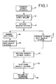
- a method for operating a back-up oxy-burner firing system is generally illustrated in the flow diagram of FIG. 1.
- a standard burner operation of a metallurgical furnace is indicated at step 10.
- the back-up oxy-burner system is activated at step 14.
- the burner can be either shut down at step 16, or alternatively, the operator can continue burner operation with the back-up system at step 18. If the burner is shut down at step 16, cooling fluid is supplied by the back-up system at step 20.
- the back-up system is shut down at step 24 and the burner is returned to standard operation at step 26.
- a varying degree of automation can be incorporated to activate and de-activate the back-up system and to return the burner to standard operation.
- flow sensors, temperature detectors, and solenoid valves can be integrated in a control system for automatic activation and de-activation of the back-up system.
- the back-up system can be manually activated by installing an air ejector in a receptacle designed to receive the air ejector using a standard quick disconnect fitting. This method is particularly advantageous if the metallurgical plant maintains a back-up liquid oxygen or nitrogen tank. The burner can then be manually activated to continue combustion operations, or alternatively, cooled by the flow of air and motive fluids from the back-up system.
- FIG. 2 A cross-sectional view of a back-up oxy-burner firing system in accordance with one embodiment of the invention is illustrated in FIG. 2.
- a motive fluid such as liquid oxygen, nitrogen, steam, air, and the like is provided through a fluid nozzle 30 at an inlet 32.
- Auxiliary air ejector 28 includes a funnel portion 34 coupled to a throat region 36.
- Throat region 36 is coupled to an oxidant conduit 38 by a coupling 40.
- Coupling 40 can be any of a variety of standard tube couplings, and in particular, coupling 40 can be a quick disconnect fitting.
- oxidant conduit 38 is positioned in proximity to a fuel conduit 52. Both oxidant conduit 38 and fuel conduit 42 are inserted into a burner block 44. In normal operation, primary oxygen flows through oxidant conduit 38 from an inlet region 46 and is injected into burner block 44 at an oxidant nozzle 48. Correspondingly, fuel enters an inlet region 50 of fuel conduit 42 and is injected into burner block 44 at fuel nozzle 52.
- auxiliary air ejector 28 entrains ambient air through an annular opening 56 and channels the ambient air to throat region 36.
- a high velocity motive fuel jet exiting fluid nozzle 30 creates a negative pressure region 60 in throat region 36.
- the negative pressure draws ambient air 54 through annular opening 56 and combines with motive fluid jet 58 to form a gas mixture 62.
- Gas mixture 62 is forced into oxidant conduit 38 and is injected into burner block 44 at oxidant nozzle 48.
- the ambient air entrainment process is put in action by slow moving ambient air molecules colliding with the fast moving motive fluid molecules.
- the bumping of slow-moving air molecules with the fast moving fluid molecules creates a bulk movement of the overall mixture.
- the net effect is a reduction in pressure in negative pressure region 60 (the venturi effect) that results in continuous entrainment of ambient air.
- Auxiliary air ejector 28 effectively "pumps" ambient air into oxy-conduit 38 by the pressure difference between annular opening 56 and throat region 36.
- motive fluid is preferably injected at a high velocity into throat region 36.
- the motive fluid such as oxygen, nitrogen, compressed air, and the like is supplied at inlet 32 of fluid nozzle 30 at a pressure of about 50 psig to about 150 psig.
- the ambient air entrainment process can be carried out by supplying clean, dry steam at a pressure of about 90 psig to about 100 psig.
- sufficient ambient air can be entrained by auxiliary air ejector 28 with a motive fluid flow rate of about 300 scfh to about 500 scfh.
- throat region 36 has an overall length of about 6 to about 12 times the diameter of throat region 36.
- the length of throat region 36 is particularly selected to take advantage of motive fluid 58 for the creation of vacuum pressure at negative pressure region 60. Additionally, the length requirements of throat region 36 provide for a fully developed motive fluid jet upon injection into oxidant conduit 38. Further, to maintain a high rate of ambient air flow, the outside diameter of annular opening 56 is preferably about 2 to about 6 times the diameter of throat region 36.
- the back-up oxy-firing system of the invention can provide combustion air in a theoretically correct stoichiometric ratio for operation of commercial oxy-burners.
- the entrainment efficiency of ambient air can be measured by determining an amplification ratio. This is the ratio of the amount of entrained air for one cubic foot of motive fluid that is injected by auxiliary air ejector 28.
- auxiliary air ejector 28 will have an amplification ratio of about 5 to about 20 depending upon the particular motive fluid and the supply pressure. For example, using liquid oxygen as a motive fluid supplied at a pressure of about 100 psig, an amplification ratio of about 10 to about 20 can be obtained.
- FIG. 2 illustrates an oxy-burner having a dedicated pipe for oxidants and a dedicated pipe for fuel
- FIG. 3 Fuel conduit 42 is partially surrounded by oxidant conduit 38.
- oxidants are injected from an annular nozzle 64 and fuel is injected from fuel nozzle 52.
- Auxiliary air ejector 28 can be attached to oxidant conduit 38 in a manner similar to that described above.
- injector designs in an oxy-burner can be dictated by parameters, such as firing capacity, flame stability, flame temperature, and the like.
- the back-up oxy-burner firing system of the invention can be operated with any type of injector configuration.
- the lock-up firing system can be used with other configurations, such as multiple injection nozzle configurations, and the like.
- An important aspect of the invention is the ability to operate an oxy-burner using auxiliary air ejector 28, while supplying motive fluid at a fraction of the primary oxygen flow required for standard operations.
- auxiliary air ejector 28 it is possible to fire up to about 40% of the rated oxy-fuel firing capacity using ambient combustion air for air-fuel combustion.
- the capacity limitation is a result of reduced flame stability caused by the higher flow velocities of the entrained ambient air through the oxidant nozzle.
- the higher flow rates cause the flame in burner block 44 to blow off, which limits the firing capacity for tube-in-tube oxy-burners, such as illustrated in FIG. 3.
- firing capacities of greater than about 40% can be obtained using ambient air.
- the greater firing capacity is due, in part, to the much lower average fuel and combustion air velocities, which increase flame stability.
- Operation of an oxy-burner using the back-up system of the invention can produce a firing rate of up to about 50 to about 60% of the normal oxy-fuel firing rate. This high firing rate is obtained by using liquid oxygen or oxygen-enriched air as the motive fluid.
- the back-up system of the invention can be operated with as little as about 18% by volume of the primary oxygen flow needed for standard operation.
- the motive fluid flow rate requirement is equivalent to about 25% by volume of the primary oxygen flow rate during standard operations.
- the furnace can be fired by the oxy-burner without interruption.
- the back-up oxy-burner firing system of the invention offers a fast, safe, reliable, and cost effective method of operating an oxy-burner during a primary oxygen failure.
- the choice of a particular motive fluid will depend on numerous parameters, such as price, availability, plant facilities, and storage availability, and the like. Examples of operating parameters for a back-up oxy-burner firing system of the invention using oxygen or nitrogen as a motive fluid are shown in Table I.
- the performance parameters set forth in Table I are for a 2MMBtuHr pipe-in-pipe oxy-burner.
- the data in Table I show that a back-up oxy-burner can be operated using the system of the invention with oxygen as a motive fluid at a flow rate of about 18% by volume of the primary oxygen flow rate.
- the total combustion gasses injected by the oxy-burner have an enrichment level of about 0.246%.
- the flow rate requirement is equivalent to about 25% of the primary oxygen flow rate.
- the overall oxygen concentration of the oxidant gas is about 0.20%.
- nitrogen operation is sufficient to entrain necessary combustion air for operation of an oxy-burner in the event of a primary oxygen failure.
- the operation of the back-up oxy-burner firing system of the invention using either oxygen or nitrogen permits operation of the oxy-burner without interruption of a high firing capacity.
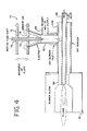
- FIG. 4 An alternative embodiment of the invention is illustrated, in cross-section, in FIG. 4.
- a primary oxygen supply line 66 is coupled to an annular oxidant conduit 68.
- An auxiliary air ejector 70 is coupled to primary oxygen supply line 66 by a standard coupling, which can be a quick disconnect fitting.
- a top plate 72 can be adjusted in a vertical direction for regulation of the quantity of ambient air entering an annular opening 74.
- a bearing 76 permits top plate 72 to vertically slide against motive fluid tube 78.
- Motive fluid is injected by fluid tube 78 into a throat region 80 of auxiliary air ejector 70. Entrained ambient air and motive fluid is forced into oxidant conduit 68 and injected into a burner block 82 at nozzle 84. Fuel is injected into burner block 82 through a fuel conduit 86.
- auxiliary air ejector 70 can be equipped with a solenoid valve (not shown) to control charging of the motive fluid. Electrical circuitry (not shown) can be incorporated to activate the motive fluid supply when a primary oxygen failure is detected. Additionally, top plate 72 can be either manually or automatically activated to adjust the amount of ambient air entrainment during operation of auxiliary air ejector 70.
- FIGS. 2-4 can be used to either continue operation of an oxy-burner, or alternatively, to provide cooling air to an oxy-burner that has been abruptly shut down.
- Supplying cooling air is crucial if the oxy-burner is self-cooled.
- Cooling air sufficient to prevent thermal damage to the oxy-burner can be provided by either auxiliary air ejector 28 or auxiliary air ejector 70 at a rate of about 300 scfh to about 500 scfh for each oxy-burner that is fitted with an auxiliary air ejector.
- the back-up oxy-burner system In addition to providing cooling air the back-up oxy-burner system also provides necessary purge air to keep process gasses within the furnace and volatile particulate matter away from the burner nozzles.
- the injection of purge air during oxy-burner shut down can prevent chemical corrosion and oxidation of the burner nozzles by gaseous species present in the furnace.
Landscapes
- Engineering & Computer Science (AREA)
- Chemical & Material Sciences (AREA)
- Combustion & Propulsion (AREA)
- Mechanical Engineering (AREA)
- General Engineering & Computer Science (AREA)
- Pre-Mixing And Non-Premixing Gas Burner (AREA)
- Air Supply (AREA)
- Ignition Installations For Internal Combustion Engines (AREA)
- Electrical Control Of Ignition Timing (AREA)
Abstract
Description
- This invention relates, in general, to oxy-burner systems for simultaneously burning gaseous or liquid fuels in the presence of oxygen or oxygen-enriched air, and more particularly, to an oxy-burner and back-up firing system and method of operation for continuously operating the oxy-burner in the event of a disruption in the oxidant supply.
- Recently, burners have been developed that use oxygen or oxygen-enriched air to support combustion of a fuel in a burner known as an oxy-burner. Oxy-burners are compact and produce typically small flames with a high power output. In conventional heating and melting operations, several different types of fuels, such as natural gas, propane, coal gas, oil, and the like, can be used to obtain the high temperatures necessary to change the furnace charge from a solid to a pre-heated or molten state. In an oxy-burner, substantially pure oxygen, generally 80% oxygen or higher, is mixed with the fuel gas to produce extremely high flame temperatures. The high flame temperatures can rapidly heat or melt the furnace charge. Rapid melting is particularly beneficial in the manufacture of iron and steel. Additionally, oxy-burners are widely used in various metallurgical plants to reduce melting time and the total energy necessary to bring the metallurgical charge to a molten state.
- Operation of an oxy-burner necessarily requires that a supply of oxygen is readily available to operate the burner. Typically, an on-site oxy generation plant, such as vacuum or pressure swing absorption units, or cryogenic air separation units are maintained in proximity to the oxy-burner. During burner operation, a continuous, uninterrupted supply of oxygen is necessary to avoid production losses and potential damage to the burner system if the supply of oxygen is interrupted. In certain non-water cooled oxy-burners, metallic parts can be damaged by furnace radiation unless the burner is pulled out of service, or cooled with auxiliary cooling air or water that is circulated to the burner nozzles.
- To limit the possibility of production losses and burner damage, metallurgical plant operations typically provide a liquid oxygen supply tank to serve as a back-up oxygen supply. The liquid oxygen supply requires continuous replenishing to compensate for evaporation losses. Because of the relatively high cost of maintaining a liquid oxygen back-up supply, many metallurgical operations fail to store sufficient back-up oxygen to meet their entire needs during a disruption in the primary oxygen supply. Additionally, because of space limitations, back-up oxygen supply tanks may not hold enough oxygen to operate the burner for the required operation.
- An alternative to on-site oxygen storage is to provide a back-up air supply system. In the event of a disruption in the oxygen supply, the oxy-burner can be operated as an air-fuel burner. Although the operation of an oxy-burner with a back-up air supply system maintains burner operation, the air must be free of lubricating grease, oils, and other contamination to avoid damaging the oxy-burner. The requirement for an extremely clean back-up air supply limits the back-up air supply system to the use of dedicated air lines and delivery equipment. The need to use dedicated equipment, such as compressors, blowers, piping performance, flow controls, and the like increases the overall capital cost of the furnace combustion system. Further, the dedicated air supply equipment requires that a relatively large amount of space be available for the installation of equipment that is used only intermittently. Moreover, after operating an oxy-burner from a back-up air system, the oxy-burner must be removed from the furnace and thoroughly cleaned to ensure that the burner has not been contaminated by air operation.
- Although oxy-burners offer a convenient means of obtaining high flame temperatures for operation of metallurgical furnaces, economic operation of the furnace requires a reliable and economic method of operation in the event of a loss in the primary oxygen supply. The economic and safety considerations in the operation of a metallurgical furnace require that a back-up firing system be safe, fast, functional and cost effective. Accordingly, a need exists for an improved back-up oxy-burner firing system and method of operation.
- The present invention is for an oxy-burner having a back-up firing system and method of operation. The back-up firing system can be used for supplying air for burner operation or for cooling burner components in the event of a disruption in the primary oxygen supply. The burner includes a fuel conduit coupled to a fuel injector nozzle, and an oxidant conduit having an oxidant injector nozzle either adjacent to or circumferential with the fuel conduit. An auxiliary air ejector is coupled to the oxidant conduit. The auxiliary air ejector is configured to receive a motive fluid and to entrain air and to force the entrained air into the oxidant conduit.
- The back-up oxy-burner firing system can use a variety of motive fluids, such as oxygen, nitrogen, steam, compressed air, and the like. Additionally, the auxiliary air ejector can be coupled to the oxidant conduit by a quick disconnect fitting. Accordingly, the auxiliary air ejector can be rapidly connected to the oxy-burner in the event of a loss in the primary oxygen supply.
- In the event of a disruption in the primary oxygen supply, the auxiliary air ejector can be put into operation to entrain ambient air and force the entrained ambient air into the oxidant conduit. The auxiliary air ejector is designed to receive motive fluid at a pressure of about 50 psig to about 150 psig, and to provide about 5 standard cubic feet per hour to about 20 standard cubic feet per hour of air for every standard cubic foot per hour of motive fluid. In operation, the auxiliary air ejector can provide an air flow rate of about 300 standard cubic feet per hour to about 500 standard cubic feet per hour. The flow rate of air is obtained with a volumetric flow rate motive fluid that is about 10 to about 40% of the primary oxygen flow rate that is used by the oxy-burner during normal operation.
-
- FIG. 1 is a schematic diagram of a method for operating a back-up oxy-burner firing system in accordance with the invention;
- FIG. 2 illustrates, in cross-section, a back-up oxy-burner firing system in accordance with one embodiment of the invention;
- FIG. 3 illustrates, in cross-section, an alternative conduit configuration; and
- FIG. 4 illustrates, in cross-section, a back-up oxy-burner firing system arranged in accordance with another embodiment of the invention.
-
- The oxy-burner with a back-up firing system and method of operation of the present invention provide an economical and effective means for rapidly dealing with a potentially catastrophic loss of the primary oxygen supply to an oxy-burner. Since the back-up firing system and method of the invention entrains ambient air and forces the air into the oxy-burner, extensive equipment and facilities are not required for emergency burner operation and cooling. As described below, the ejector system of the invention can be operated with a number of motive fluids that are readily available at a metallurgical plant. Additionally, the air ejector operates with a motive fluid supplied at a pressure and flow rate that is commonly available on-site at metallurgical operating facilities. Accordingly, upon detection of a failure in the primary oxygen supply, the back-up oxy-firing system can be quickly brought on line and economically operated to either continue furnace operations, or alternatively, to supply cooling air to burner components.
- A method for operating a back-up oxy-burner firing system is generally illustrated in the flow diagram of FIG. 1. A standard burner operation of a metallurgical furnace is indicated at step 10. Upon detection of a primary oxygen supply failure at
step 12, the back-up oxy-burner system is activated atstep 14. In accordance with the invention, the burner can be either shut down atstep 16, or alternatively, the operator can continue burner operation with the back-up system atstep 18. If the burner is shut down atstep 16, cooling fluid is supplied by the back-up system at step 20. Upon restoring the primary oxygen supply atstep 22, the back-up system is shut down atstep 24 and the burner is returned to standard operation atstep 26. - Those skilled in the art will appreciate that a varying degree of automation can be incorporated to activate and de-activate the back-up system and to return the burner to standard operation. For example, flow sensors, temperature detectors, and solenoid valves can be integrated in a control system for automatic activation and de-activation of the back-up system. Alternatively, the back-up system can be manually activated by installing an air ejector in a receptacle designed to receive the air ejector using a standard quick disconnect fitting. This method is particularly advantageous if the metallurgical plant maintains a back-up liquid oxygen or nitrogen tank. The burner can then be manually activated to continue combustion operations, or alternatively, cooled by the flow of air and motive fluids from the back-up system.
- A cross-sectional view of a back-up oxy-burner firing system in accordance with one embodiment of the invention is illustrated in FIG. 2. A motive fluid, such as liquid oxygen, nitrogen, steam, air, and the like is provided through a
fluid nozzle 30 at aninlet 32.Auxiliary air ejector 28 includes afunnel portion 34 coupled to athroat region 36.Throat region 36 is coupled to anoxidant conduit 38 by acoupling 40.Coupling 40 can be any of a variety of standard tube couplings, and in particular, coupling 40 can be a quick disconnect fitting. - In the embodiment illustrated in FIG. 2,
oxidant conduit 38 is positioned in proximity to afuel conduit 52. Bothoxidant conduit 38 andfuel conduit 42 are inserted into aburner block 44. In normal operation, primary oxygen flows throughoxidant conduit 38 from aninlet region 46 and is injected intoburner block 44 at anoxidant nozzle 48. Correspondingly, fuel enters aninlet region 50 offuel conduit 42 and is injected intoburner block 44 atfuel nozzle 52. - In operation,
auxiliary air ejector 28 entrains ambient air through anannular opening 56 and channels the ambient air tothroat region 36. A high velocity motive fuel jet exitingfluid nozzle 30 creates anegative pressure region 60 inthroat region 36. The negative pressure drawsambient air 54 throughannular opening 56 and combines withmotive fluid jet 58 to form agas mixture 62.Gas mixture 62 is forced intooxidant conduit 38 and is injected intoburner block 44 atoxidant nozzle 48. - The ambient air entrainment process is put in action by slow moving ambient air molecules colliding with the fast moving motive fluid molecules. The bumping of slow-moving air molecules with the fast moving fluid molecules creates a bulk movement of the overall mixture. The net effect is a reduction in pressure in negative pressure region 60 (the venturi effect) that results in continuous entrainment of ambient air.
Auxiliary air ejector 28 effectively "pumps" ambient air into oxy-conduit 38 by the pressure difference betweenannular opening 56 andthroat region 36. - To create the ambient air entrainment process, motive fluid is preferably injected at a high velocity into
throat region 36. Preferably, the motive fluid, such as oxygen, nitrogen, compressed air, and the like is supplied atinlet 32 offluid nozzle 30 at a pressure of about 50 psig to about 150 psig. Alternatively, the ambient air entrainment process can be carried out by supplying clean, dry steam at a pressure of about 90 psig to about 100 psig. Additionally, sufficient ambient air can be entrained byauxiliary air ejector 28 with a motive fluid flow rate of about 300 scfh to about 500 scfh. Those skilled in the art will appreciate that the particular values of supply pressure and motive fluid flow rate will depend upon factors, such as the particular motive fluid, the geometric characteristics of the auxiliary air ejector, the required firing rate of the particular furnace, required flame temperatures, and the like. - In a preferred embodiment of the invention,
throat region 36 has an overall length of about 6 to about 12 times the diameter ofthroat region 36. The length ofthroat region 36 is particularly selected to take advantage ofmotive fluid 58 for the creation of vacuum pressure atnegative pressure region 60. Additionally, the length requirements ofthroat region 36 provide for a fully developed motive fluid jet upon injection intooxidant conduit 38. Further, to maintain a high rate of ambient air flow, the outside diameter ofannular opening 56 is preferably about 2 to about 6 times the diameter ofthroat region 36. - The back-up oxy-firing system of the invention can provide combustion air in a theoretically correct stoichiometric ratio for operation of commercial oxy-burners. The entrainment efficiency of ambient air can be measured by determining an amplification ratio. This is the ratio of the amount of entrained air for one cubic foot of motive fluid that is injected by
auxiliary air ejector 28. In operation,auxiliary air ejector 28 will have an amplification ratio of about 5 to about 20 depending upon the particular motive fluid and the supply pressure. For example, using liquid oxygen as a motive fluid supplied at a pressure of about 100 psig, an amplification ratio of about 10 to about 20 can be obtained. - Those skilled in the art will appreciate that various types of burner injector arrangements are commonly used in commercial oxy-burners. While FIG. 2 illustrates an oxy-burner having a dedicated pipe for oxidants and a dedicated pipe for fuel, an alternative design is illustrated in FIG. 3.
Fuel conduit 42 is partially surrounded byoxidant conduit 38. Inburner block 44, oxidants are injected from anannular nozzle 64 and fuel is injected fromfuel nozzle 52.Auxiliary air ejector 28 can be attached tooxidant conduit 38 in a manner similar to that described above. Those skilled in the art will appreciate that different injector designs in an oxy-burner can be dictated by parameters, such as firing capacity, flame stability, flame temperature, and the like. The back-up oxy-burner firing system of the invention can be operated with any type of injector configuration. In addition to those illustrated in FIGS. 2 and 3, the lock-up firing system can be used with other configurations, such as multiple injection nozzle configurations, and the like. - An important aspect of the invention is the ability to operate an oxy-burner using
auxiliary air ejector 28, while supplying motive fluid at a fraction of the primary oxygen flow required for standard operations. In many oxy-burners, it is possible to fire up to about 40% of the rated oxy-fuel firing capacity using ambient combustion air for air-fuel combustion. The capacity limitation is a result of reduced flame stability caused by the higher flow velocities of the entrained ambient air through the oxidant nozzle. The higher flow rates cause the flame inburner block 44 to blow off, which limits the firing capacity for tube-in-tube oxy-burners, such as illustrated in FIG. 3. In oxy-burner designs having multiple fuel and oxidant conduits, firing capacities of greater than about 40% can be obtained using ambient air. The greater firing capacity is due, in part, to the much lower average fuel and combustion air velocities, which increase flame stability. Operation of an oxy-burner using the back-up system of the invention can produce a firing rate of up to about 50 to about 60% of the normal oxy-fuel firing rate. This high firing rate is obtained by using liquid oxygen or oxygen-enriched air as the motive fluid. In addition to higher firing rates, the back-up system of the invention can be operated with as little as about 18% by volume of the primary oxygen flow needed for standard operation. Correspondingly, where nitrogen is used as the motive fluid, the motive fluid flow rate requirement is equivalent to about 25% by volume of the primary oxygen flow rate during standard operations. Importantly, while using liquid oxygen, nitrogen, or other motive fluid, the furnace can be fired by the oxy-burner without interruption. Regardless of the particular motive fluid used, the back-up oxy-burner firing system of the invention offers a fast, safe, reliable, and cost effective method of operating an oxy-burner during a primary oxygen failure. The choice of a particular motive fluid will depend on numerous parameters, such as price, availability, plant facilities, and storage availability, and the like. Examples of operating parameters for a back-up oxy-burner firing system of the invention using oxygen or nitrogen as a motive fluid are shown in Table I.Ejector Performance Parameters Motive Fluid Burner Firing Rate (MM Btu/Hr) NG Flow Rate (scfh) Primary Oxygen Flow Rate (scfh) Entrained Combustion Air Flow Requirement (scfh) Motive Fluid Supply Pressure (psig) Motive Fluid Flow Rate (scfh) Oxygen Conc. In Oxidant Mixture Amp. Ratio of the Ejector Oxygen 2.00 2,000 4,000 15,500 100 750 0.246 20 Nitrogen 2.00 2,000 4,000 22,000 100 1,100 0.20 20 - The performance parameters set forth in Table I are for a 2MMBtuHr pipe-in-pipe oxy-burner. The data in Table I show that a back-up oxy-burner can be operated using the system of the invention with oxygen as a motive fluid at a flow rate of about 18% by volume of the primary oxygen flow rate.
- The total combustion gasses injected by the oxy-burner have an enrichment level of about 0.246%. Correspondingly, where nitrogen is used as a motive fluid, the flow rate requirement is equivalent to about 25% of the primary oxygen flow rate. With the use of nitrogen, the overall oxygen concentration of the oxidant gas is about 0.20%. In many cases, nitrogen operation is sufficient to entrain necessary combustion air for operation of an oxy-burner in the event of a primary oxygen failure. The operation of the back-up oxy-burner firing system of the invention using either oxygen or nitrogen permits operation of the oxy-burner without interruption of a high firing capacity.
- An alternative embodiment of the invention is illustrated, in cross-section, in FIG. 4. A primary
oxygen supply line 66 is coupled to anannular oxidant conduit 68. Anauxiliary air ejector 70 is coupled to primaryoxygen supply line 66 by a standard coupling, which can be a quick disconnect fitting. Atop plate 72 can be adjusted in a vertical direction for regulation of the quantity of ambient air entering anannular opening 74. A bearing 76 permits topplate 72 to vertically slide againstmotive fluid tube 78. Motive fluid is injected byfluid tube 78 into athroat region 80 ofauxiliary air ejector 70. Entrained ambient air and motive fluid is forced intooxidant conduit 68 and injected into aburner block 82 atnozzle 84. Fuel is injected intoburner block 82 through afuel conduit 86. - For automated operation,
auxiliary air ejector 70 can be equipped with a solenoid valve (not shown) to control charging of the motive fluid. Electrical circuitry (not shown) can be incorporated to activate the motive fluid supply when a primary oxygen failure is detected. Additionally,top plate 72 can be either manually or automatically activated to adjust the amount of ambient air entrainment during operation ofauxiliary air ejector 70. - It is important to note that the embodiments of the invention illustrated in FIGS. 2-4 can be used to either continue operation of an oxy-burner, or alternatively, to provide cooling air to an oxy-burner that has been abruptly shut down. Supplying cooling air is crucial if the oxy-burner is self-cooled. Cooling air sufficient to prevent thermal damage to the oxy-burner can be provided by either
auxiliary air ejector 28 orauxiliary air ejector 70 at a rate of about 300 scfh to about 500 scfh for each oxy-burner that is fitted with an auxiliary air ejector. In addition to providing cooling air the back-up oxy-burner system also provides necessary purge air to keep process gasses within the furnace and volatile particulate matter away from the burner nozzles. The injection of purge air during oxy-burner shut down can prevent chemical corrosion and oxidation of the burner nozzles by gaseous species present in the furnace. - Thus it is apparent that there has been described an oxy-burner having a back-up firing system and method of operation that fully provides the advantages set forth above. Those skilled in the art will recognize that numerous modifications can be made without departing from the spirit of the invention. For example, numerous geometric variations of the auxiliary air ejectors illustrated herein can be made to perform the function of supplying air for burner operation and for cooling. Accordingly, all such variations and modifications are within the scope of the appended claims and equivalents thereof.
Claims (20)
- An oxy-burner having a back-up firing system for supplying air for oxidation and for cooling to the oxy-burner in the event of a disruption in the primary oxygen supply, the oxy-burner comprising:a fuel conduit coupled to a fuel injector nozzle;an oxygen induction apparatus, including an oxidant conduit coupled to an oxidant injector nozzle and a primary oxygen line coupled to the oxidant conduit for transporting oxygen into the oxidant conduit; andan auxiliary air ejector coupled to the oxidant conduit,wherein the auxiliary air ejector is configured to receive a motive fluid and to entrain air and to force the entrained air into the oxidant conduit.
- The oxy-burner of claim 1, wherein the motive fluid is selected from the group consisting of liquid oxygen, nitrogen, steam, and compressed air.
- The oxy-burner of claim 1, wherein the oxygen conduit is configured to transport substantially pure oxygen.
- The oxy-burner of claim 1, wherein the auxiliary air ejector is coupled to a primary oxygen inlet line by a coupling comprising a quick disconnect fitting.
- The oxy-burner of claim 1, wherein the auxiliary air ejection comprises an inlet having a first diameter and a throat region having a second diameter, and wherein the first diameter is about 2 to about 4 times larger than the second diameter.
- The oxy-burner of claim 5, wherein the auxiliary air ejector further comprises a mixing tube coupled to the throat, wherein the mixing tube is characterized by a length and by a diameter, and wherein the ratio of the length to the diameter is about 6 to about 12.
- A method for supplying air for oxidation and for cooling to an oxy-burner in the event of a disruption in the primary oxygen supply, the method comprising:providing an auxiliary air ejector coupled to an oxidant conduit, wherein the auxiliary air ejector is configured to receive a motive fluid and to entrain ambient air and to force the entrained ambient air into the oxidant conduit;upon detecting a disruption in the primary oxygen, supplying a motive fluid to the auxiliary air ejector; andflowing air into the oxy-burner.
- The method of claim 7, wherein the step of supplying a motive fluid comprises supplying a fluid selected from the group consisting of liquid oxygen, nitrogen, steam and compressed air.
- The method of claim 7, wherein the primary oxygen is supplied at a predetermined flow rate, and wherein the step of supplying a motive fluid comprises flowing the motive fluid at a flow rate of about 10 to about 40% by volume of the predetermined flow rate.
- The method of claim 7, wherein the step of supplying a motive fluid comprises supplying motive fluid at a pressure of about 50 to about 150 psig.
- The method of claim 7, wherein the steps of supplying a motive fluid and flowing air comprise flowing about 5 to about 20 scfh of air for every scfh of motive fluid.
- The method of claim 7, wherein the step of flowing air comprises flowing air at a flow rate of about 300 scfh to about 500 scfh.
- The method of claim 9, wherein the step of supplying a motive fluid comprises flowing oxygen at a flow rate of about 18% by volume of the predetermined flow rate.
- The method of claim 7, wherein the step of supplying motive fluid comprises flowing nitrogen at a flow rate of about 27% by volume of the predetermined flow rate.
- A method for supplying a fluid for oxidation and for cooling to an oxy-burner in the event of a disruption in the primary oxygen supply, the method comprising:providing an auxiliary air system coupled to an oxidant conduit wherein the auxiliary air system is configured to receive a motive fluid and to entrain air and to force the entrained air into the oxidant conduit;activating the auxiliary air system upon detecting a disruption in the primary oxygen supply; andflowing motive fluid and entrained air into the oxy-burner.
- The method of claim 15, wherein the step of activating the auxiliary air system comprises the steps of:supplying motive fluid at a pressure of about 50 to about 150 psig; andoperating the oxy-burner using the entrained air and motive supplied by the auxiliary air system.
- The method of claim 16, wherein the step of supplying motive fluid comprises supplying a fluid selected from the group consisting of liquid oxygen, nitrogen, steam, and compressed air.
- The method of claim 17, wherein the primary oxygen is supplied at a predetermined flow rate, and wherein the step of supplying a motive fluid comprises supplying the motive fluid at a flow rate of about 10 to about 40% by volume of the predetermined flow rate.
- The method of claim 15, wherein the step of activating the auxiliary air system comprises the steps of:supplying a motive fluid selected from the group consisting of nitrogen and air;discontinuing the operation of the oxy-burner; andcooling the oxy-burner using the entrained air and the motive fluid supplied by the auxiliary air system.
- The method of claim 19, wherein the step of supplying a motive fluid comprises supplying motive fluid at a flow rate of about 300 scfh to about 500 scfh.
Applications Claiming Priority (2)
| Application Number | Priority Date | Filing Date | Title |
|---|---|---|---|
| US09/464,921 US6155818A (en) | 1999-12-16 | 1999-12-16 | Oxy-burner having a back-up firing system and method of operation |
| US464921 | 1999-12-16 |
Publications (2)
| Publication Number | Publication Date |
|---|---|
| EP1108954A1 true EP1108954A1 (en) | 2001-06-20 |
| EP1108954B1 EP1108954B1 (en) | 2004-06-16 |
Family
ID=23845803
Family Applications (1)
| Application Number | Title | Priority Date | Filing Date |
|---|---|---|---|
| EP00403468A Expired - Lifetime EP1108954B1 (en) | 1999-12-16 | 2000-12-11 | Oxy-burner having a back-up firing system and method of operation. |
Country Status (7)
| Country | Link |
|---|---|
| US (1) | US6155818A (en) |
| EP (1) | EP1108954B1 (en) |
| JP (1) | JP4800475B2 (en) |
| AT (1) | ATE269513T1 (en) |
| DE (1) | DE60011558T2 (en) |
| ES (1) | ES2222167T3 (en) |
| ID (1) | ID28676A (en) |
Cited By (2)
| Publication number | Priority date | Publication date | Assignee | Title |
|---|---|---|---|---|
| DE102008058420A1 (en) * | 2008-11-21 | 2010-05-27 | Air Liquide Deutschland Gmbh | Method for heating component, involves operating atmospheric heating burner with fuel and gas mixture containing oxygen |
| WO2022006012A1 (en) * | 2020-06-30 | 2022-01-06 | Applied Materials, Inc. | Gas entrainment during jetting of fluid for temperature control in chemical mechanical polishing |
Families Citing this family (12)
| Publication number | Priority date | Publication date | Assignee | Title |
|---|---|---|---|---|
| US6155818A (en) * | 1999-12-16 | 2000-12-05 | L'air Liquide, Societe Anonyme Pour L'etude Et, L'exploitation Des Procedes, Georges Claude | Oxy-burner having a back-up firing system and method of operation |
| US7096671B2 (en) * | 2003-10-14 | 2006-08-29 | Siemens Westinghouse Power Corporation | Catalytic combustion system and method |
| US7581948B2 (en) * | 2005-12-21 | 2009-09-01 | Johns Manville | Burner apparatus and methods for making inorganic fibers |
| US7802452B2 (en) | 2005-12-21 | 2010-09-28 | Johns Manville | Processes for making inorganic fibers |
| DE102006010237A1 (en) * | 2006-03-02 | 2007-09-13 | Otto Huthmann | Combustion method and fuel boiler assembly therefor |
| JP4910449B2 (en) * | 2006-03-29 | 2012-04-04 | 株式会社Ihi | Regenerative burner, heating furnace and soaking furnace |
| RU2515928C2 (en) * | 2008-06-05 | 2014-05-20 | Агк Гласс Юроп | Glass melting furnace |
| JP5451455B2 (en) * | 2010-03-01 | 2014-03-26 | 大陽日酸株式会社 | Burner burning method |
| EP2487439B1 (en) * | 2011-02-14 | 2019-05-08 | General Electric Technology GmbH | Method and system for milling a fuel for an oxy-fuel combustion burner |
| US9574770B2 (en) * | 2012-04-17 | 2017-02-21 | Alter Nrg Corp. | Start-up torch |
| CH711812A1 (en) * | 2015-11-26 | 2017-05-31 | Carboforce Sàrl | Burner. |
| CA3199871A1 (en) * | 2020-11-20 | 2022-05-27 | Kevin EICHHORN | Radio frequency moisture-removal |
Citations (6)
| Publication number | Priority date | Publication date | Assignee | Title |
|---|---|---|---|---|
| GB405285A (en) * | 1932-07-25 | 1934-01-25 | Paul Bornkessel | A method and apparatus for producing gas-air-oxygen mixtures |
| US4443183A (en) * | 1981-07-21 | 1984-04-17 | Osaka Gas Company Limited | Combustion apparatus |
| US5145361A (en) * | 1984-12-04 | 1992-09-08 | Combustion Research, Inc. | Burner and method for metallurgical heating and melting |
| US5865206A (en) * | 1997-05-09 | 1999-02-02 | Praxair Technology, Inc. | Process and apparatus for backing-up or supplementing a gas supply system |
| FR2783595A1 (en) * | 1998-09-22 | 2000-03-24 | Air Liquide | METHOD FOR HEATING AN OVEN |
| US6155818A (en) * | 1999-12-16 | 2000-12-05 | L'air Liquide, Societe Anonyme Pour L'etude Et, L'exploitation Des Procedes, Georges Claude | Oxy-burner having a back-up firing system and method of operation |
Family Cites Families (16)
| Publication number | Priority date | Publication date | Assignee | Title |
|---|---|---|---|---|
| CH532752A (en) * | 1971-02-25 | 1973-01-15 | Finterm Spa | Combustion head for burners |
| US4130388A (en) * | 1976-09-15 | 1978-12-19 | Flynn Burner Corporation | Non-contaminating fuel burner |
| EP0085925A3 (en) * | 1982-02-09 | 1983-10-12 | Charles Richard Gerlach | Burner with variable air controller |
| BR8405390A (en) * | 1983-10-21 | 1985-09-03 | Air Prod & Chem | HEATING APPLIANCE |
| USH19H (en) * | 1983-12-21 | 1986-02-04 | The United States Of America As Represented By The United States Department Of Energy | Fuel injection device and method |
| US4547150A (en) * | 1984-05-10 | 1985-10-15 | Midland-Ross Corporation | Control system for oxygen enriched air burner |
| DE3666625D1 (en) * | 1985-02-21 | 1989-11-30 | Tauranca Ltd | Fluid fuel fired burner |
| SE450731B (en) * | 1985-11-22 | 1987-07-20 | Aga Ab | VALVE DEVICE FOR ENCOURAGING A GAS, EX COMBUSTION AIR, WITH ANOTHER GAS EXV OXYGEN |
| US4874310A (en) * | 1988-02-25 | 1989-10-17 | Selas Corporation Of America | Low NOX burner |
| US4954076A (en) * | 1989-07-28 | 1990-09-04 | Air Products And Chemicals, Inc. | Flame stabilized oxy-fuel recirculating burner |
| US5199866A (en) * | 1992-03-30 | 1993-04-06 | Air Products And Chemicals, Inc. | Adjustable momentum self-cooled oxy/fuel burner for heating in high temperature environments |
| US5518395A (en) * | 1993-04-30 | 1996-05-21 | General Electric Company | Entrainment fuel nozzle for partial premixing of gaseous fuel and air to reduce emissions |
| US5516279A (en) * | 1994-07-06 | 1996-05-14 | The Boc Group, Inc. | Oxy-fuel burner system designed for alternate fuel usage |
| US5567141A (en) * | 1994-12-30 | 1996-10-22 | Combustion Tec, Inc. | Oxy-liquid fuel combustion process and apparatus |
| JP3380409B2 (en) * | 1996-12-05 | 2003-02-24 | 東京瓦斯株式会社 | Oxygen-enriched combustion burner |
| FR2771798B1 (en) * | 1997-12-02 | 1999-12-31 | Air Liquide | OXY-FUEL BURNER |
-
1999
- 1999-12-16 US US09/464,921 patent/US6155818A/en not_active Expired - Lifetime
-
2000
- 2000-12-11 EP EP00403468A patent/EP1108954B1/en not_active Expired - Lifetime
- 2000-12-11 ES ES00403468T patent/ES2222167T3/en not_active Expired - Lifetime
- 2000-12-11 AT AT00403468T patent/ATE269513T1/en not_active IP Right Cessation
- 2000-12-11 DE DE60011558T patent/DE60011558T2/en not_active Expired - Lifetime
- 2000-12-15 ID IDP20001091D patent/ID28676A/en unknown
- 2000-12-18 JP JP2000383525A patent/JP4800475B2/en not_active Expired - Fee Related
Patent Citations (6)
| Publication number | Priority date | Publication date | Assignee | Title |
|---|---|---|---|---|
| GB405285A (en) * | 1932-07-25 | 1934-01-25 | Paul Bornkessel | A method and apparatus for producing gas-air-oxygen mixtures |
| US4443183A (en) * | 1981-07-21 | 1984-04-17 | Osaka Gas Company Limited | Combustion apparatus |
| US5145361A (en) * | 1984-12-04 | 1992-09-08 | Combustion Research, Inc. | Burner and method for metallurgical heating and melting |
| US5865206A (en) * | 1997-05-09 | 1999-02-02 | Praxair Technology, Inc. | Process and apparatus for backing-up or supplementing a gas supply system |
| FR2783595A1 (en) * | 1998-09-22 | 2000-03-24 | Air Liquide | METHOD FOR HEATING AN OVEN |
| US6155818A (en) * | 1999-12-16 | 2000-12-05 | L'air Liquide, Societe Anonyme Pour L'etude Et, L'exploitation Des Procedes, Georges Claude | Oxy-burner having a back-up firing system and method of operation |
Cited By (7)
| Publication number | Priority date | Publication date | Assignee | Title |
|---|---|---|---|---|
| DE102008058420A1 (en) * | 2008-11-21 | 2010-05-27 | Air Liquide Deutschland Gmbh | Method for heating component, involves operating atmospheric heating burner with fuel and gas mixture containing oxygen |
| WO2022006012A1 (en) * | 2020-06-30 | 2022-01-06 | Applied Materials, Inc. | Gas entrainment during jetting of fluid for temperature control in chemical mechanical polishing |
| US11577358B2 (en) | 2020-06-30 | 2023-02-14 | Applied Materials, Inc. | Gas entrainment during jetting of fluid for temperature control in chemical mechanical polishing |
| TWI797659B (en) * | 2020-06-30 | 2023-04-01 | 美商應用材料股份有限公司 | Gas entrainment during jetting of fluid for temperature control in chemical mechanical polishing |
| TWI851044B (en) * | 2020-06-30 | 2024-08-01 | 美商應用材料股份有限公司 | Chemical mechanical polishing system |
| TWI896215B (en) * | 2020-06-30 | 2025-09-01 | 美商應用材料股份有限公司 | Chemical mechanical polishing system |
| US12528151B2 (en) | 2020-06-30 | 2026-01-20 | Applied Materials, Inc. | Gas entrainment during jetting of fluid for temperature control in chemical mechanical polishing |
Also Published As
| Publication number | Publication date |
|---|---|
| DE60011558D1 (en) | 2004-07-22 |
| ATE269513T1 (en) | 2004-07-15 |
| EP1108954B1 (en) | 2004-06-16 |
| JP2001193923A (en) | 2001-07-17 |
| US6155818A (en) | 2000-12-05 |
| ES2222167T3 (en) | 2005-02-01 |
| JP4800475B2 (en) | 2011-10-26 |
| ID28676A (en) | 2001-06-21 |
| DE60011558T2 (en) | 2005-08-18 |
Similar Documents
| Publication | Publication Date | Title |
|---|---|---|
| US6155818A (en) | Oxy-burner having a back-up firing system and method of operation | |
| JP3527471B2 (en) | Furnace high temperature maintenance method | |
| RU2492389C2 (en) | Multi-mode device for realisation of combustion and method of this device usage | |
| US8967995B1 (en) | High-efficiency dual flare system | |
| KR101768717B1 (en) | Primary oxidant feed to oxy-fired circulating fluidized bed | |
| US20060057517A1 (en) | Oxidant injection method | |
| KR20010039760A (en) | FUEL DILUTION METHODS AND APPARATUS FOR NOx REDUCTION | |
| KR900006242B1 (en) | Primary air exchanger of pulverized coal burner and its replacement method | |
| US4083398A (en) | Waste heat recovery system | |
| US3169161A (en) | Oxygen-fuel probe | |
| US4180128A (en) | Multiple furnace waste heat recovery system | |
| US20020026997A1 (en) | Heat recovery type heat storage apparatus | |
| US7249946B2 (en) | Thermal generator and combustion method for limiting nitrogen oxides emissions by re-combustion of fumes | |
| CN88101247A (en) | Be used for the gasifier burner cools system of under hyperbaric environment, working | |
| CN101198821B (en) | Circulating fluidized bed device with oxygen combustion furnace | |
| DK166923B1 (en) | PROCEDURE FOR REGULATING A PFBC INSTALLATION BY OPERATING PREVENTION IN THE GAS TURBINE UNIT AND A PFBC INSTALLATION WITH EQUIPMENT FOR SUCH REGULATION | |
| CN109737438B (en) | Cooling device and cooling method for high-temperature flue gas | |
| JP4503612B2 (en) | Gas turbine equipment, low calorie gas supply equipment, and method for suppressing calorie rise of the gas | |
| US20170074590A1 (en) | Change-out system for submerged combustion melting burner | |
| EP3339730B1 (en) | Staged combustion installation and method | |
| JP4546482B2 (en) | Gas turbine equipment, low calorie gas supply equipment, and method for suppressing calorie rise of the gas | |
| WO1994020414A1 (en) | Sulfur dioxide generation using granulated or emulsoid sulfur feedstock | |
| US8317897B2 (en) | Method for supersonically injecting oxygen into a furnace | |
| JP5389335B2 (en) | Gasifier | |
| KR100865239B1 (en) | Pulverized coal blower for dual cooling and complete combustion of fines |
Legal Events
| Date | Code | Title | Description |
|---|---|---|---|
| PUAI | Public reference made under article 153(3) epc to a published international application that has entered the european phase |
Free format text: ORIGINAL CODE: 0009012 |
|
| AK | Designated contracting states |
Kind code of ref document: A1 Designated state(s): AT BE CH CY DE DK ES FI FR GB GR IE IT LI LU MC NL PT SE TR |
|
| AX | Request for extension of the european patent |
Free format text: AL;LT;LV;MK;RO;SI |
|
| 17P | Request for examination filed |
Effective date: 20011220 |
|
| AKX | Designation fees paid |
Free format text: AT BE CH CY DE DK ES FI FR GB GR IE IT LI LU MC NL PT SE TR |
|
| RAP1 | Party data changed (applicant data changed or rights of an application transferred) |
Owner name: L'AIR LIQUIDE, S.A. A DIRECTOIRE ET CONSEIL DE SUR |
|
| 17Q | First examination report despatched |
Effective date: 20030409 |
|
| GRAP | Despatch of communication of intention to grant a patent |
Free format text: ORIGINAL CODE: EPIDOSNIGR1 |
|
| GRAS | Grant fee paid |
Free format text: ORIGINAL CODE: EPIDOSNIGR3 |
|
| GRAA | (expected) grant |
Free format text: ORIGINAL CODE: 0009210 |
|
| AK | Designated contracting states |
Kind code of ref document: B1 Designated state(s): AT BE CH CY DE DK ES FI FR GB GR IE IT LI LU MC NL PT SE TR |
|
| PG25 | Lapsed in a contracting state [announced via postgrant information from national office to epo] |
Ref country code: CH Free format text: LAPSE BECAUSE OF FAILURE TO SUBMIT A TRANSLATION OF THE DESCRIPTION OR TO PAY THE FEE WITHIN THE PRESCRIBED TIME-LIMIT Effective date: 20040616 Ref country code: FI Free format text: LAPSE BECAUSE OF FAILURE TO SUBMIT A TRANSLATION OF THE DESCRIPTION OR TO PAY THE FEE WITHIN THE PRESCRIBED TIME-LIMIT Effective date: 20040616 Ref country code: CY Free format text: LAPSE BECAUSE OF FAILURE TO SUBMIT A TRANSLATION OF THE DESCRIPTION OR TO PAY THE FEE WITHIN THE PRESCRIBED TIME-LIMIT Effective date: 20040616 Ref country code: AT Free format text: LAPSE BECAUSE OF FAILURE TO SUBMIT A TRANSLATION OF THE DESCRIPTION OR TO PAY THE FEE WITHIN THE PRESCRIBED TIME-LIMIT Effective date: 20040616 Ref country code: TR Free format text: LAPSE BECAUSE OF FAILURE TO SUBMIT A TRANSLATION OF THE DESCRIPTION OR TO PAY THE FEE WITHIN THE PRESCRIBED TIME-LIMIT Effective date: 20040616 Ref country code: LI Free format text: LAPSE BECAUSE OF FAILURE TO SUBMIT A TRANSLATION OF THE DESCRIPTION OR TO PAY THE FEE WITHIN THE PRESCRIBED TIME-LIMIT Effective date: 20040616 |
|
| REG | Reference to a national code |
Ref country code: GB Ref legal event code: FG4D |
|
| REG | Reference to a national code |
Ref country code: CH Ref legal event code: EP |
|
| REF | Corresponds to: |
Ref document number: 60011558 Country of ref document: DE Date of ref document: 20040722 Kind code of ref document: P |
|
| REG | Reference to a national code |
Ref country code: IE Ref legal event code: FG4D |
|
| PG25 | Lapsed in a contracting state [announced via postgrant information from national office to epo] |
Ref country code: GR Free format text: LAPSE BECAUSE OF FAILURE TO SUBMIT A TRANSLATION OF THE DESCRIPTION OR TO PAY THE FEE WITHIN THE PRESCRIBED TIME-LIMIT Effective date: 20040916 Ref country code: SE Free format text: LAPSE BECAUSE OF FAILURE TO SUBMIT A TRANSLATION OF THE DESCRIPTION OR TO PAY THE FEE WITHIN THE PRESCRIBED TIME-LIMIT Effective date: 20040916 Ref country code: DK Free format text: LAPSE BECAUSE OF FAILURE TO SUBMIT A TRANSLATION OF THE DESCRIPTION OR TO PAY THE FEE WITHIN THE PRESCRIBED TIME-LIMIT Effective date: 20040916 |
|
| PG25 | Lapsed in a contracting state [announced via postgrant information from national office to epo] |
Ref country code: LU Free format text: LAPSE BECAUSE OF NON-PAYMENT OF DUE FEES Effective date: 20041211 |
|
| PG25 | Lapsed in a contracting state [announced via postgrant information from national office to epo] |
Ref country code: IE Free format text: LAPSE BECAUSE OF NON-PAYMENT OF DUE FEES Effective date: 20041213 |
|
| PG25 | Lapsed in a contracting state [announced via postgrant information from national office to epo] |
Ref country code: MC Free format text: LAPSE BECAUSE OF NON-PAYMENT OF DUE FEES Effective date: 20041231 |
|
| REG | Reference to a national code |
Ref country code: CH Ref legal event code: PL |
|
| REG | Reference to a national code |
Ref country code: ES Ref legal event code: FG2A Ref document number: 2222167 Country of ref document: ES Kind code of ref document: T3 |
|
| ET | Fr: translation filed | ||
| PLBE | No opposition filed within time limit |
Free format text: ORIGINAL CODE: 0009261 |
|
| STAA | Information on the status of an ep patent application or granted ep patent |
Free format text: STATUS: NO OPPOSITION FILED WITHIN TIME LIMIT |
|
| 26N | No opposition filed |
Effective date: 20050317 |
|
| REG | Reference to a national code |
Ref country code: IE Ref legal event code: MM4A |
|
| PG25 | Lapsed in a contracting state [announced via postgrant information from national office to epo] |
Ref country code: PT Free format text: LAPSE BECAUSE OF NON-PAYMENT OF DUE FEES Effective date: 20041116 |
|
| PGFP | Annual fee paid to national office [announced via postgrant information from national office to epo] |
Ref country code: GB Payment date: 20131219 Year of fee payment: 14 Ref country code: DE Payment date: 20131220 Year of fee payment: 14 |
|
| PGFP | Annual fee paid to national office [announced via postgrant information from national office to epo] |
Ref country code: NL Payment date: 20131219 Year of fee payment: 14 Ref country code: ES Payment date: 20131220 Year of fee payment: 14 Ref country code: IT Payment date: 20131217 Year of fee payment: 14 |
|
| PGFP | Annual fee paid to national office [announced via postgrant information from national office to epo] |
Ref country code: BE Payment date: 20131219 Year of fee payment: 14 |
|
| PGFP | Annual fee paid to national office [announced via postgrant information from national office to epo] |
Ref country code: FR Payment date: 20131220 Year of fee payment: 14 |
|
| PG25 | Lapsed in a contracting state [announced via postgrant information from national office to epo] |
Ref country code: BE Free format text: LAPSE BECAUSE OF NON-PAYMENT OF DUE FEES Effective date: 20141231 |
|
| REG | Reference to a national code |
Ref country code: DE Ref legal event code: R119 Ref document number: 60011558 Country of ref document: DE |
|
| REG | Reference to a national code |
Ref country code: NL Ref legal event code: V1 Effective date: 20150701 |
|
| REG | Reference to a national code |
Ref country code: NL Ref legal event code: V1 Effective date: 20150701 |
|
| GBPC | Gb: european patent ceased through non-payment of renewal fee |
Effective date: 20141211 |
|
| REG | Reference to a national code |
Ref country code: FR Ref legal event code: ST Effective date: 20150831 |
|
| PG25 | Lapsed in a contracting state [announced via postgrant information from national office to epo] |
Ref country code: NL Free format text: LAPSE BECAUSE OF NON-PAYMENT OF DUE FEES Effective date: 20150701 |
|
| PG25 | Lapsed in a contracting state [announced via postgrant information from national office to epo] |
Ref country code: GB Free format text: LAPSE BECAUSE OF NON-PAYMENT OF DUE FEES Effective date: 20141211 Ref country code: DE Free format text: LAPSE BECAUSE OF NON-PAYMENT OF DUE FEES Effective date: 20150701 |
|
| PG25 | Lapsed in a contracting state [announced via postgrant information from national office to epo] |
Ref country code: FR Free format text: LAPSE BECAUSE OF NON-PAYMENT OF DUE FEES Effective date: 20141231 |
|
| PG25 | Lapsed in a contracting state [announced via postgrant information from national office to epo] |
Ref country code: IT Free format text: LAPSE BECAUSE OF NON-PAYMENT OF DUE FEES Effective date: 20141211 |
|
| REG | Reference to a national code |
Ref country code: ES Ref legal event code: FD2A Effective date: 20160128 |
|
| PG25 | Lapsed in a contracting state [announced via postgrant information from national office to epo] |
Ref country code: ES Free format text: LAPSE BECAUSE OF NON-PAYMENT OF DUE FEES Effective date: 20141212 |