EP1108884A2 - Threaded filter housing to retain water separator bowl - Google Patents
Threaded filter housing to retain water separator bowl Download PDFInfo
- Publication number
- EP1108884A2 EP1108884A2 EP00125631A EP00125631A EP1108884A2 EP 1108884 A2 EP1108884 A2 EP 1108884A2 EP 00125631 A EP00125631 A EP 00125631A EP 00125631 A EP00125631 A EP 00125631A EP 1108884 A2 EP1108884 A2 EP 1108884A2
- Authority
- EP
- European Patent Office
- Prior art keywords
- water separator
- fuel filter
- filter assembly
- separator bowl
- filter housing
- Prior art date
- Legal status (The legal status is an assumption and is not a legal conclusion. Google has not performed a legal analysis and makes no representation as to the accuracy of the status listed.)
- Withdrawn
Links
- XLYOFNOQVPJJNP-UHFFFAOYSA-N water Substances O XLYOFNOQVPJJNP-UHFFFAOYSA-N 0.000 title claims abstract description 42
- 239000000446 fuel Substances 0.000 claims abstract description 43
- 239000002184 metal Substances 0.000 claims description 4
- 229920000642 polymer Polymers 0.000 claims description 3
- 239000004677 Nylon Substances 0.000 claims description 2
- 229910000831 Steel Inorganic materials 0.000 claims description 2
- 239000004433 Thermoplastic polyurethane Substances 0.000 claims description 2
- 229920001778 nylon Polymers 0.000 claims description 2
- 239000010959 steel Substances 0.000 claims description 2
- 229920002725 thermoplastic elastomer Polymers 0.000 claims description 2
- 229920002803 thermoplastic polyurethane Polymers 0.000 claims description 2
- KZTYYGOKRVBIMI-UHFFFAOYSA-N diphenyl sulfone Chemical compound C=1C=CC=CC=1S(=O)(=O)C1=CC=CC=C1 KZTYYGOKRVBIMI-UHFFFAOYSA-N 0.000 claims 1
- 229920001971 elastomer Polymers 0.000 claims 1
- 239000000806 elastomer Substances 0.000 claims 1
- 238000003466 welding Methods 0.000 description 4
- 239000002828 fuel tank Substances 0.000 description 3
- 238000000034 method Methods 0.000 description 3
- 239000013536 elastomeric material Substances 0.000 description 2
- 238000004519 manufacturing process Methods 0.000 description 2
- 239000000203 mixture Substances 0.000 description 2
- -1 poly(phenylsulfone) Polymers 0.000 description 2
- 238000000071 blow moulding Methods 0.000 description 1
- 238000000748 compression moulding Methods 0.000 description 1
- 238000009833 condensation Methods 0.000 description 1
- 230000005494 condensation Effects 0.000 description 1
- 238000010276 construction Methods 0.000 description 1
- 238000001746 injection moulding Methods 0.000 description 1
- JEIPFZHSYJVQDO-UHFFFAOYSA-N iron(III) oxide Inorganic materials O=[Fe]O[Fe]=O JEIPFZHSYJVQDO-UHFFFAOYSA-N 0.000 description 1
- 238000000465 moulding Methods 0.000 description 1
- 238000007789 sealing Methods 0.000 description 1
- 239000002904 solvent Substances 0.000 description 1
- 239000000126 substance Substances 0.000 description 1
- 238000003856 thermoforming Methods 0.000 description 1
Images
Classifications
-
- B—PERFORMING OPERATIONS; TRANSPORTING
- B01—PHYSICAL OR CHEMICAL PROCESSES OR APPARATUS IN GENERAL
- B01D—SEPARATION
- B01D36/00—Filter circuits or combinations of filters with other separating devices
- B01D36/003—Filters in combination with devices for the removal of liquids
-
- F—MECHANICAL ENGINEERING; LIGHTING; HEATING; WEAPONS; BLASTING
- F02—COMBUSTION ENGINES; HOT-GAS OR COMBUSTION-PRODUCT ENGINE PLANTS
- F02M—SUPPLYING COMBUSTION ENGINES IN GENERAL WITH COMBUSTIBLE MIXTURES OR CONSTITUENTS THEREOF
- F02M37/00—Apparatus or systems for feeding liquid fuel from storage containers to carburettors or fuel-injection apparatus; Arrangements for purifying liquid fuel specially adapted for, or arranged on, internal-combustion engines
- F02M37/22—Arrangements for purifying liquid fuel specially adapted for, or arranged on, internal-combustion engines, e.g. arrangements in the feeding system
- F02M37/24—Arrangements for purifying liquid fuel specially adapted for, or arranged on, internal-combustion engines, e.g. arrangements in the feeding system characterised by water separating means
- F02M37/26—Arrangements for purifying liquid fuel specially adapted for, or arranged on, internal-combustion engines, e.g. arrangements in the feeding system characterised by water separating means with water detection means
-
- F—MECHANICAL ENGINEERING; LIGHTING; HEATING; WEAPONS; BLASTING
- F02—COMBUSTION ENGINES; HOT-GAS OR COMBUSTION-PRODUCT ENGINE PLANTS
- F02M—SUPPLYING COMBUSTION ENGINES IN GENERAL WITH COMBUSTIBLE MIXTURES OR CONSTITUENTS THEREOF
- F02M37/00—Apparatus or systems for feeding liquid fuel from storage containers to carburettors or fuel-injection apparatus; Arrangements for purifying liquid fuel specially adapted for, or arranged on, internal-combustion engines
- F02M37/22—Arrangements for purifying liquid fuel specially adapted for, or arranged on, internal-combustion engines, e.g. arrangements in the feeding system
- F02M37/32—Arrangements for purifying liquid fuel specially adapted for, or arranged on, internal-combustion engines, e.g. arrangements in the feeding system characterised by filters or filter arrangements
Definitions
- the present invention relates generally to a fuel filter assembly with a filter housing, having a rolled thread for attaching a water separator bowl directly to the filter housing.
- This invention relates generally to a fuel filter assembly, preferably for use on a vehicle.
- fuel tanks for earthmoving vehicles are of substantial capacity, it is general practice to add fuel to the tanks from large drums or cans stored at the work site.
- these drums are usually stored outdoors so that rain water collects on the drums and can inadvertently mix with the fuel. Condensation also adds moisture as the tank is warmed and cooled with temperature fluctuations.
- water can get into the fuel in the tank.
- the water and fuel are agitated so that a fuel and water mixture is fed to the engine's fuel system. This causes engine operating problems, and excessive wear of moving parts particularly in the fuel system.
- the water in the tank and associated passages produces rust, which in turn is fed into the fuel supply system and results in clogging and/or greater rates of engine wear.
- prior water separators generally caused leakage past the threads on the drain valve as the operator drained the collected water from the bowl. This allows water and fuel to leak out during draining getting the operators hands dirty and spilling fuel to the ground.
- a fuel filter assembly having an annular filter housing with a rolled thread to attach directly to a threaded water separator bowl.
- a seal member is interposed the annular filter housing and the threaded water separator bowl.
- a fuel filter assembly 2 of the present invention is depicted.
- a top plate 3 is shown in Fig. 1 assembled within an annular fuel filter housing 4.
- the annular fuel filter housing 4 more particularly a canister, has a first end portion 5 and a second end portion 6.
- the second end portion 6 has a rolled thread 10, preferably formed integrally thereon.
- the annual fuel filter housing 4 is preferably made from a metal, more preferably steel.
- a threaded water separator bowl 12 is supported by the second end portion 6 of the annular fuel filter housing 4 and is releasably engaged therewith.
- the threaded water separator bowl 12 is preferably made from, but not limited to, a polymer, more preferably a rigid polymer with temperature and chemical resistance, such as amorphous nylon, poly(phenylsulfone), thermoplastic polyurethane and the like.
- the threaded water separator bowl 12 is made of metal.
- the threaded water separator bowl 12 may be of unitary construction or may be constructed from two individually molded parts which are then unified.
- the threaded water separator bowl 12 is preferably formed integrally from two individually molded parts by ultrasonic welding. It is contemplated that several molding processes may be utilized to form the two individually molded parts, including, but not limited to, injection molding, blow molding, compression molding, and thermoforming.
- the processes include, but are not limiting to, ultrasonic welding, rotational welding, and solvent welding.
- a drain valve assembly 14 for draining the water collected in the threaded water separator bowl 12 includes a drain valve 18 and a drain port 16.
- the drain valve 18 is preferably constructed of a thermoplastic elastomer. The elastomeric material allows a slight interference fit, which prevents the passage of fuel past the thread. It also allows the valve to be rotated during opening with little effort unlike a hard valve with interference fit. There are also two radial seals on the drain valve 18 which are molded directly into the drain valve 18.
- a seal member 20 is interposed between the fuel filter housing 4 and the threaded water separator bowl 12 for sealing the assembly.
- a water sensor port 22 in the fuel filter assembly 2 for a water sensor.
- the rolled thread 10 is produced integrally with the second end portion 6 of the annular filter housing 4.
- the drain valve assembly 14, including the drain valve 18 and the drain port 16, may be included in the fuel filter assembly 2.
- the drain valve 18 in Fig. 2 is preferably made of an elastomeric material to give a slight interference fit. This prevents the passage of fuel past the thread during draining.
- a integral rolled thread 10 of the second end portion 6 of the annular filter housing 4 is provided that eliminates the need for a threaded adapter collar for attaching the threaded water separator bowl 12. This eliminates the adapter piece which adds additional cost and manufacturing efficiency.
Landscapes
- Engineering & Computer Science (AREA)
- Chemical & Material Sciences (AREA)
- Combustion & Propulsion (AREA)
- Mechanical Engineering (AREA)
- General Engineering & Computer Science (AREA)
- Chemical Kinetics & Catalysis (AREA)
- Filtration Of Liquid (AREA)
Abstract
Description
- The present invention relates generally to a fuel filter assembly with a filter housing, having a rolled thread for attaching a water separator bowl directly to the filter housing.
- This invention relates generally to a fuel filter assembly, preferably for use on a vehicle. While fuel tanks for earthmoving vehicles are of substantial capacity, it is general practice to add fuel to the tanks from large drums or cans stored at the work site. Unfortunately, these drums are usually stored outdoors so that rain water collects on the drums and can inadvertently mix with the fuel. Condensation also adds moisture as the tank is warmed and cooled with temperature fluctuations. As a consequence of these outdoor conditions, such as the necessity of filling the fuel tanks in rainy weather, water can get into the fuel in the tank. During subsequent operation of the vehicle the water and fuel are agitated so that a fuel and water mixture is fed to the engine's fuel system. This causes engine operating problems, and excessive wear of moving parts particularly in the fuel system. In addition, the water in the tank and associated passages produces rust, which in turn is fed into the fuel supply system and results in clogging and/or greater rates of engine wear.
- Many attempts have been proposed for removing water from the fuel tank, such as a water separator installed in a suitable position in the fuel supply system. The prior art utilized a water separator bowl, a filter housing, and a threaded adapter collar for attaching the water separator bowl to the filter housing.
- One example is U.S. Pat. No. 5,904,844, issued 18 May 1999, and assigned to Parker Intangibles Inc., which utilized a threaded adapter ring to attach the water separator bowl and the filter housing. The threaded adapter ring was applied by adhering the ring to the filter housing. The additional adapter piece adds additional cost and reduces manufacturing efficiency.
- Moreover, prior water separators generally caused leakage past the threads on the drain valve as the operator drained the collected water from the bowl. This allows water and fuel to leak out during draining getting the operators hands dirty and spilling fuel to the ground.
- In one aspect of the invention, a fuel filter assembly is provided having an annular filter housing with a rolled thread to attach directly to a threaded water separator bowl. A seal member is interposed the annular filter housing and the threaded water separator bowl.
-
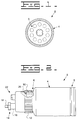
- Fig. 1 is a top view of the fuel filter assembly; and
- Fig. 2 is a side view of the fuel filter assembly.
-
- Turning to the drawings, a
fuel filter assembly 2 of the present invention is depicted. Atop plate 3 is shown in Fig. 1 assembled within an annularfuel filter housing 4. - The annular fuel filter housing 4, more particularly a canister, has a
first end portion 5 and asecond end portion 6. Thesecond end portion 6 has a rolledthread 10, preferably formed integrally thereon. The annualfuel filter housing 4 is preferably made from a metal, more preferably steel. - A threaded water separator bowl 12 is supported by the
second end portion 6 of the annularfuel filter housing 4 and is releasably engaged therewith. The threaded water separator bowl 12 is preferably made from, but not limited to, a polymer, more preferably a rigid polymer with temperature and chemical resistance, such as amorphous nylon, poly(phenylsulfone), thermoplastic polyurethane and the like. In an alternate embodiment, the threaded water separator bowl 12 is made of metal. - The threaded water separator bowl 12 may be of unitary construction or may be constructed from two individually molded parts which are then unified. The threaded water separator bowl 12 is preferably formed integrally from two individually molded parts by ultrasonic welding. It is contemplated that several molding processes may be utilized to form the two individually molded parts, including, but not limited to, injection molding, blow molding, compression molding, and thermoforming.
- It is also contemplated that several processes may be utilized to attach the two individually molded parts to integrally form the threaded water separator bowl 12. The processes include, but are not limiting to, ultrasonic welding, rotational welding, and solvent welding.
- In one embodiment of the present invention, a
drain valve assembly 14 for draining the water collected in the threaded water separator bowl 12 includes adrain valve 18 and adrain port 16. Thedrain valve 18 is preferably constructed of a thermoplastic elastomer. The elastomeric material allows a slight interference fit, which prevents the passage of fuel past the thread. It also allows the valve to be rotated during opening with little effort unlike a hard valve with interference fit. There are also two radial seals on thedrain valve 18 which are molded directly into thedrain valve 18. - A
seal member 20 is interposed between thefuel filter housing 4 and the threaded water separator bowl 12 for sealing the assembly. - As shown in Fig. 2, in one embodiment, there is also a
water sensor port 22 in thefuel filter assembly 2 for a water sensor. - During use of the
fuel filter assembly 2 as set forth in Figs. 1 and 2, the integral rolled thread of thesecond end portion 6 of theannular filter housing 4 attaches directly to the threaded water separator bowl 12. - As illustrated in Fig. 2, during the making of the
annual filter housing 4, the rolledthread 10 is produced integrally with thesecond end portion 6 of theannular filter housing 4. - As shown in Fig. 2, the
drain valve assembly 14, including thedrain valve 18 and thedrain port 16, may be included in thefuel filter assembly 2. Thedrain valve 18 in Fig. 2 is preferably made of an elastomeric material to give a slight interference fit. This prevents the passage of fuel past the thread during draining.
In view of the above, it is readily apparent that a integral rolledthread 10 of thesecond end portion 6 of theannular filter housing 4 is provided that eliminates the need for a threaded adapter collar for attaching the threaded water separator bowl 12. This eliminates the adapter piece which adds additional cost and manufacturing efficiency. - Other aspects, objects and advantages of this invention can be obtained from a study of the drawings, the disclosure and the appended claims.
Claims (15)
- A fuel filter assembly (2) comprising:a top plate (3);an annular filter housing (4) having a first end portion (5) and a second end portion (6), said second end portion (6) having a rolled thread (10) being formed integrally therewith;a threaded water separator bowl (12) supported by said second end portion (6) and releasably engaged therewith; anda seal member (20) interposed said annular filter housing (4) and said threaded water separator bowl (12).
- The fuel filter assembly (2) as in claim 1, wherein said filter housing (4) is metal.
- The fuel filter assembly (2) as in claim 2, wherein said filter housing (4) is steel.
- The fuel filter assembly (2) as in claim 2, wherein said filter housing (4) is a canister.
- The fuel filter assembly (2) as in claim 1, wherein said rolled thread (10) is an external thread.
- The fuel filter assembly (2) as in claim 1, wherein said threaded water separator bowl (12) includes a drain valve assembly (14) for draining said threaded water separator bowl (12).
- The fuel filter assembly (2) as in claim 6, wherein said drain valve assembly (14) includes a drain valve (18) and a drain (16).
- The fuel filter assembly (2) as in claim 1, wherein said threaded water separator bowl (12) is a polymer.
- The fuel filter assembly (2) as in claim 8, wherein said threaded water separator bowl (12) is nylon.
- The fuel filter assembly (2) as in claim 8, wherein said threaded water separator bowl (12) is poly (phenylsulfone).
- The fuel filter assembly (2) as in claim 8, wherein said threaded water separator bowl (12) is thermoplastic polyurethane.
- The fuel filter assembly (2) as in claim 1, wherein said threaded water separator bowl (12) is metal.
- The fuel filter assembly (2) as in claim 1, wherein said drain valve (18) is an elastomer.
- The fuel filter assembly (2) as in claim 1, wherein said drain valve (18) is a thermoplastic elastomer.
- The fuel filter assembly (2) as in claim 1, wherein said threaded water separator bowl (12) includes a water sensor port (22).
Applications Claiming Priority (2)
| Application Number | Priority Date | Filing Date | Title |
|---|---|---|---|
| US46075299A | 1999-12-14 | 1999-12-14 | |
| US460752 | 1999-12-14 |
Publications (2)
| Publication Number | Publication Date |
|---|---|
| EP1108884A2 true EP1108884A2 (en) | 2001-06-20 |
| EP1108884A3 EP1108884A3 (en) | 2001-12-12 |
Family
ID=23829943
Family Applications (1)
| Application Number | Title | Priority Date | Filing Date |
|---|---|---|---|
| EP00125631A Withdrawn EP1108884A3 (en) | 1999-12-14 | 2000-11-23 | Threaded filter housing to retain water separator bowl |
Country Status (2)
| Country | Link |
|---|---|
| EP (1) | EP1108884A3 (en) |
| JP (1) | JP2001190909A (en) |
Cited By (2)
| Publication number | Priority date | Publication date | Assignee | Title |
|---|---|---|---|---|
| WO2013056942A1 (en) * | 2011-10-21 | 2013-04-25 | Land Rover | Apparatus for mounting on a rotatable portion of a diesel filter |
| US11028807B2 (en) | 2016-10-21 | 2021-06-08 | Cummins Filtration Ip, Inc. | Bowl for filter assemblies |
Citations (1)
| Publication number | Priority date | Publication date | Assignee | Title |
|---|---|---|---|---|
| US5904844A (en) | 1985-05-14 | 1999-05-18 | Parker Intangibles Inc. | Fuel filter element |
Family Cites Families (4)
| Publication number | Priority date | Publication date | Assignee | Title |
|---|---|---|---|---|
| US4624779A (en) * | 1985-09-10 | 1986-11-25 | Hurner Erwin E | Fuel treatment apparatus |
| US4724074A (en) * | 1985-10-07 | 1988-02-09 | Parker Hannifin Corporation | Self-venting drain assembly |
| DE3701259A1 (en) * | 1986-01-29 | 1987-07-30 | Volkswagen Ag | DEVICE FOR REMOVING WATER FROM THE FUEL PIPING SYSTEM OF AN INTERNAL COMBUSTION ENGINE |
| US4933093A (en) * | 1989-04-20 | 1990-06-12 | Keller Russel D | Fuel filter |
-
2000
- 2000-11-23 EP EP00125631A patent/EP1108884A3/en not_active Withdrawn
- 2000-12-13 JP JP2000378658A patent/JP2001190909A/en not_active Withdrawn
Patent Citations (1)
| Publication number | Priority date | Publication date | Assignee | Title |
|---|---|---|---|---|
| US5904844A (en) | 1985-05-14 | 1999-05-18 | Parker Intangibles Inc. | Fuel filter element |
Cited By (5)
| Publication number | Priority date | Publication date | Assignee | Title |
|---|---|---|---|---|
| WO2013056942A1 (en) * | 2011-10-21 | 2013-04-25 | Land Rover | Apparatus for mounting on a rotatable portion of a diesel filter |
| GB2492426B (en) * | 2011-10-21 | 2015-04-08 | Jaguar Land Rover Ltd | A finger grip wheel |
| US10001096B2 (en) | 2011-10-21 | 2018-06-19 | Jaguar Land Rover Limited | Apparatus for mounting on a rotatable portion of a diesel filter |
| US11028807B2 (en) | 2016-10-21 | 2021-06-08 | Cummins Filtration Ip, Inc. | Bowl for filter assemblies |
| US11781512B2 (en) | 2016-10-21 | 2023-10-10 | Cummins Filtration Ip, Inc | Bowl for filter assemblies |
Also Published As
| Publication number | Publication date |
|---|---|
| JP2001190909A (en) | 2001-07-17 |
| EP1108884A3 (en) | 2001-12-12 |
Similar Documents
| Publication | Publication Date | Title |
|---|---|---|
| US4593714A (en) | Manhole assembly with water barrier | |
| EP0381925B1 (en) | Self-venting drain valve assembly | |
| US20080000724A1 (en) | Drain Valve | |
| US5765612A (en) | Quick-connect engine oil drainage system | |
| US20050109685A1 (en) | Fuel tank | |
| US5630451A (en) | Oil change apparatus | |
| US5857503A (en) | Apparatus and method for changing fluid in a motor vehicle | |
| JP2006205952A (en) | Fuel tank breather equipment | |
| US8940165B2 (en) | Oil-filter device | |
| US6585889B2 (en) | Transmission oil pan module having filter with integrated drain plug | |
| SE459644B (en) | FILTER DEVICE | |
| EP1108884A2 (en) | Threaded filter housing to retain water separator bowl | |
| US6769516B2 (en) | Oil containment boot and method of using same | |
| MX2007000950A (en) | Oil sump especially for an internal combustion engine. | |
| US5819822A (en) | Fluid filler tool for a spin-on fluid filter | |
| US9162564B2 (en) | Fuel tank | |
| US5100443A (en) | Air filter assembly | |
| US6810759B2 (en) | Engine starter | |
| JPH0515922Y2 (en) | ||
| US7727390B2 (en) | Oil filter device for an internal combustion engine | |
| EP1777407A1 (en) | Diesel filter | |
| EP1731725A2 (en) | Oil pan for automotive engines and method of making same | |
| CN114608225A (en) | Closing plug for a collector of a refrigerant circuit | |
| US20040226878A1 (en) | Overflow-catching shell for an oil or fuel filter | |
| US20090090720A1 (en) | Retaining cap |
Legal Events
| Date | Code | Title | Description |
|---|---|---|---|
| PUAI | Public reference made under article 153(3) epc to a published international application that has entered the european phase |
Free format text: ORIGINAL CODE: 0009012 |
|
| AK | Designated contracting states |
Kind code of ref document: A2 Designated state(s): AT BE CH CY DE DK ES FI FR GB GR IE IT LI LU MC NL PT SE TR Kind code of ref document: A2 Designated state(s): DE GB IT |
|
| AX | Request for extension of the european patent |
Free format text: AL;LT;LV;MK;RO;SI |
|
| PUAL | Search report despatched |
Free format text: ORIGINAL CODE: 0009013 |
|
| AK | Designated contracting states |
Kind code of ref document: A3 Designated state(s): AT BE CH CY DE DK ES FI FR GB GR IE IT LI LU MC NL PT SE TR |
|
| AX | Request for extension of the european patent |
Free format text: AL;LT;LV;MK;RO;SI |
|
| AKX | Designation fees paid |
Free format text: DE GB IT |
|
| STAA | Information on the status of an ep patent application or granted ep patent |
Free format text: STATUS: THE APPLICATION IS DEEMED TO BE WITHDRAWN |
|
| 18D | Application deemed to be withdrawn |
Effective date: 20020613 |