EP1108542A1 - Continuous ink jet system having non-circular orifices - Google Patents
Continuous ink jet system having non-circular orifices Download PDFInfo
- Publication number
- EP1108542A1 EP1108542A1 EP00204311A EP00204311A EP1108542A1 EP 1108542 A1 EP1108542 A1 EP 1108542A1 EP 00204311 A EP00204311 A EP 00204311A EP 00204311 A EP00204311 A EP 00204311A EP 1108542 A1 EP1108542 A1 EP 1108542A1
- Authority
- EP
- European Patent Office
- Prior art keywords
- nozzle bore
- heater
- orifice
- long axis
- ink
- Prior art date
- Legal status (The legal status is an assumption and is not a legal conclusion. Google has not performed a legal analysis and makes no representation as to the accuracy of the status listed.)
- Granted
Links
Images


Classifications
-
- B—PERFORMING OPERATIONS; TRANSPORTING
- B41—PRINTING; LINING MACHINES; TYPEWRITERS; STAMPS
- B41J—TYPEWRITERS; SELECTIVE PRINTING MECHANISMS, i.e. MECHANISMS PRINTING OTHERWISE THAN FROM A FORME; CORRECTION OF TYPOGRAPHICAL ERRORS
- B41J2/00—Typewriters or selective printing mechanisms characterised by the printing or marking process for which they are designed
- B41J2/005—Typewriters or selective printing mechanisms characterised by the printing or marking process for which they are designed characterised by bringing liquid or particles selectively into contact with a printing material
- B41J2/01—Ink jet
- B41J2/015—Ink jet characterised by the jet generation process
- B41J2/02—Ink jet characterised by the jet generation process generating a continuous ink jet
- B41J2/03—Ink jet characterised by the jet generation process generating a continuous ink jet by pressure
-
- B—PERFORMING OPERATIONS; TRANSPORTING
- B41—PRINTING; LINING MACHINES; TYPEWRITERS; STAMPS
- B41J—TYPEWRITERS; SELECTIVE PRINTING MECHANISMS, i.e. MECHANISMS PRINTING OTHERWISE THAN FROM A FORME; CORRECTION OF TYPOGRAPHICAL ERRORS
- B41J2/00—Typewriters or selective printing mechanisms characterised by the printing or marking process for which they are designed
- B41J2/005—Typewriters or selective printing mechanisms characterised by the printing or marking process for which they are designed characterised by bringing liquid or particles selectively into contact with a printing material
- B41J2/01—Ink jet
- B41J2/07—Ink jet characterised by jet control
- B41J2/105—Ink jet characterised by jet control for binary-valued deflection
-
- B—PERFORMING OPERATIONS; TRANSPORTING
- B41—PRINTING; LINING MACHINES; TYPEWRITERS; STAMPS
- B41J—TYPEWRITERS; SELECTIVE PRINTING MECHANISMS, i.e. MECHANISMS PRINTING OTHERWISE THAN FROM A FORME; CORRECTION OF TYPOGRAPHICAL ERRORS
- B41J2/00—Typewriters or selective printing mechanisms characterised by the printing or marking process for which they are designed
- B41J2/005—Typewriters or selective printing mechanisms characterised by the printing or marking process for which they are designed characterised by bringing liquid or particles selectively into contact with a printing material
- B41J2/01—Ink jet
- B41J2/015—Ink jet characterised by the jet generation process
- B41J2/02—Ink jet characterised by the jet generation process generating a continuous ink jet
- B41J2/03—Ink jet characterised by the jet generation process generating a continuous ink jet by pressure
- B41J2002/032—Deflection by heater around the nozzle
-
- B—PERFORMING OPERATIONS; TRANSPORTING
- B41—PRINTING; LINING MACHINES; TYPEWRITERS; STAMPS
- B41J—TYPEWRITERS; SELECTIVE PRINTING MECHANISMS, i.e. MECHANISMS PRINTING OTHERWISE THAN FROM A FORME; CORRECTION OF TYPOGRAPHICAL ERRORS
- B41J2/00—Typewriters or selective printing mechanisms characterised by the printing or marking process for which they are designed
- B41J2/005—Typewriters or selective printing mechanisms characterised by the printing or marking process for which they are designed characterised by bringing liquid or particles selectively into contact with a printing material
- B41J2/01—Ink jet
- B41J2/135—Nozzles
- B41J2/14—Structure thereof only for on-demand ink jet heads
- B41J2002/14475—Structure thereof only for on-demand ink jet heads characterised by nozzle shapes or number of orifices per chamber
-
- B—PERFORMING OPERATIONS; TRANSPORTING
- B41—PRINTING; LINING MACHINES; TYPEWRITERS; STAMPS
- B41J—TYPEWRITERS; SELECTIVE PRINTING MECHANISMS, i.e. MECHANISMS PRINTING OTHERWISE THAN FROM A FORME; CORRECTION OF TYPOGRAPHICAL ERRORS
- B41J2202/00—Embodiments of or processes related to ink-jet or thermal heads
- B41J2202/01—Embodiments of or processes related to ink-jet heads
- B41J2202/16—Nozzle heaters
Definitions
- This invention relates generally to the field of digitally controlled printing devices, and in particular to continuous ink jet print heads which integrate multiple nozzles on a single substrate and in which the breakup of a liquid ink stream into droplets is caused by a periodic disturbance of the liquid ink stream.
- Ink jet printing has become recognized as a prominent contender in the digitally controlled, electronic printing arena because of, e.g., its non-impact, low-noise characteristics, its use of plain paper and its avoidance of toner transfers and fixing.
- Ink jet printing mechanisms can be categorized as either continuous ink jet or drop-on-demand ink jet. Continuous ink jet printing dates back to at least 1929. See U.S. Patent No. 1,941,001 to Hansell.
- U.K. Patent Application GB 2 041 831A discloses a mechanism in which a deflector steers an ink jet by the Coanda (wall attachment) effect.
- the degree of deflection can be varied by moving the position of the deflector or by changing the amplitude of perturbations in the jet.
- Another ink jet printer includes a delivery channel for pressurized ink to establish a continuous flow of ink in a stream flowing from a nozzle bore.
- a heater having a selectively-actuated section associated with only a portion of the nozzle bore perimeter causes the stream to break up into a plurality of droplets at a position spaced from the heater. Actuation of the heater section produces an asymmetric application of heat to the stream to control the direction of the stream between a print direction and a non-print direction. Also by, using semiconductor VLSI fabrication processes and equipment, and by incorporating addressing and driving circuits on the same silicon substrate as the nozzles, a dense linear array of nozzles can be produced.
- inkjet printers may contain multiple arrays, all of which may be located on the same silicon substrate. Each array could then emit a different color ink. Full-width and full-color ink jet printers can thus be manufactured, which can print at high speeds and produce high-quality color prints.
- an object of the present invention is to provide an improved digitally controlled printing system capable of producing high-quality color images at a high speed and low cost, using standard paper.
- an apparatus for controlling ink in a continuous ink jet printer including an ink delivery channel; a nozzle bore which opens into the ink delivery channel to establish a continuous flow of ink in a stream; a heater having a plurality of selectively independently actuated sections which are positioned along respectively different portions of the nozzle bore's perimeter.
- An actuator selectively activates none, one, or a plurality of the heater sections such that actuation of heater sections associated with only a portion of the entire nozzle bore perimeter produces an asymmetric application of heat to the stream to control the direction of the stream between a print direction and a non-print direction. Simultaneous actuation of different numbers of heater sections associated with only a portion of the entire nozzle bore perimeter produces a corresponding different asymmetric application of heat to the stream to thereby control the direction of the stream between one print direction and another print direction.
- the nozzle bore preferably has an opening with an aspect ratio greater than unity.
- the aspect ratio is a ratio of the long axis to the short axis of the nozzle bore.
- Any non-circular nozzle bore is contemplated, however, it is preferred that reflection symmetry exists about the nozzle bore's long axis. It is also contemplated that reflection symmetry may exist about the nozzle bore's short axis in conjunction with reflection symmetry about the nozzle bore's long axis.
- FIG. 1 through FIG. 7 the apparatus generally shown in FIG. 1 through FIG. 7. It will be appreciated that the apparatus may vary as to configuration and as to details of the parts without departing from the basic concepts as disclosed herein.
- a continuous ink jet printer system includes an image source 10 such as a scanner or computer which provides raster image data, outline image data in the form of a page description language, or other forms of digital image data.
- This image data is converted to multi-level, half-toned bitmap image data by an image processing unit 12 which also stores the image data in memory.
- a plurality of heater control circuits 14 read data from the image memory and apply time-varying electrical pulses to a set of nozzle heaters 50 that are part of a print head 16. These pulses are applied at an appropriate time, and to the appropriate nozzle, so that drops formed from a continuous ink jet stream will form spots on a recording medium 18 in the appropriate position designated by the data in the image memory.
- Recording medium 18 is moved relative to print head 16 by a recording medium transport system 20, which is electronically controlled by a recording medium transport control system 22, and which in turn is controlled by a micro-controller 24.
- the recording medium transport system shown in FIG. 1 is a schematic only, and many different mechanical configurations are possible.
- a transfer roller could be used as recording medium transport system 20 to facilitate transfer of the ink drops to recording medium 18.
- Such transfer roller technology is well known in the art.
- page-width print heads it is most convenient to move recording medium 18 past a stationary print head.
- scanning print systems it is usually most convenient to move the print head along one axis (the sub-scanning direction) and the recording medium along an orthogonal axis (the main scanning direction) in a relative raster motion.
- Ink is contained in an ink reservoir 28 under pressure.
- continuous ink jet drop streams are unable to reach recording medium 18 due to an ink gutter 17 that blocks the stream and which may allow a portion of the ink to be recycled by an ink recycling unit 19.
- the ink recycling unit reconditions the ink and feeds it back to reservoir 28.
- Such ink recycling units are well known in the art.
- the ink pressure suitable for optimal operation will depend on a number of factors, including geometry and thermal properties of the nozzles and thermal properties of the ink.
- a constant ink pressure can be achieved by applying pressure to ink reservoir 28 under the control of ink pressure regulator 26.
- the ink is distributed to the back surface of print head 16 by an ink channel device 30.
- the ink preferably flows through slots and/or holes etched through a silicon substrate of print head 16 to its front surface, where a plurality of nozzles and heaters 50 are situated.
- print head 16 fabricated from silicon, it is possible to integrate heater control circuits 14 with print head 16.
- FIG. 2 a cross-sectional view of one nozzle of an array of such nozzles that form continuous ink jet print head 16 of FIG. 1, according to a preferred embodiment of the preferred invention.
- An ink delivery channel 40, along with a plurality of nozzle bores 46 are etched in a substrate 42, which is silicon in this example.
- Delivery channel 40 and nozzle bores 46 may be formed by anisotropic wet etching of silicon, using a p+ etch stop layer to form nozzle bores 46.
- Ink 70 in delivery channel 40 is pressurized above atmospheric pressure, and forms a stream 60. At a distance above nozzle bore 46, stream 60 breaks into a plurality of drops 66 due to a periodic heat pulse supplied by a heater 50.
- Heater 50 is separated from substrate 42 by thermal and insulating layers 56 to minimize heat loss to substrate.
- Nozzle bore 46 may be etched allowing the nozzle exit orifice to be defined by insulating layers 56.
- heater 50 has two sections 58a and 58b, each covering approximately one-half of the perimeter of nozzle bore 46.
- the power connections 72a and 72b and the ground connections 74a and 74b from the drive circuitry to heater 50 are also shown.
- Stream 60 may be deflected by an asymmetric application of heat by supplying electrical current to one, but not both, of heater sections 58a and 58b.
- This technology is distinct from that of prior systems of electrostatic continuous-stream deflection printers, which rely upon deflection of charged drops previously separated from their respective streams.
- drops 66 shown in FIG. 2
- drops 66 may be blocked from reaching recording medium 18 by a cut-off device such as an ink gutter 17.
- ink gutter 17 may be placed to block deflected drops 66 so that un-deflected drops 67 will be allowed to reach recording medium 18.
- an important system parameter is the angle at which the ink fluid deflects.
- This angle denoted by ⁇ , is shown in FIG. 2. It is the angle formed between a line connecting the deflected drops to the center of nozzle bore 46 on the surface of electrical insulating layers 56 and a line normal to the electrical insulating layers 56 centered at nozzle bore 46. Greater drop deflection results in a more robust system.
- the larger the deflection angle ⁇ the closer ink gutter 17 may be placed relative to printhead 16, and hence, printhead 16 can be placed closer to recording medium 18.
- This distance D is shown in FIG. 2. In general, shorter drop travel distance D will result in lower drop placement errors, which will result in higher image quality.
- larger deflection angles ⁇ result in larger deflected drop 66 to ink gutter 17 spacing, shown as S in FIG. 2.
- a larger deflected drop 66 to ink gutter 17 spacing would allow a larger ink gutter 17 to printhead 16 alignment tolerance.
- Larger deflection angles ⁇ also allow for larger amounts of (unintended) undeflected drop 67 misdirection. Undeflected drop misdirection may occur, for instance, due to fabrication non-uniformity from nozzle to nozzle or due to dirt, debris, deposits, or the like, that may form in or around nozzle bore 46.
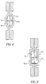
- Nozzle bore 76 and 78 may be of any non-circular shape, however, it is preferred that reflection symmetry exists about its long axis, depicted by "a”. It is also contemplated that reflection symmetry may exist about the nozzle bore's short axis, depicted by "b", in conjunction with reflection symmetry about the nozzle bore's long axis. Non-circular orifices yield improved deflection angles ⁇ for fluid stream 60 exiting therefrom.
- Nozzle bore 76 and 78 has an opening with an aspect ratio greater than 1.0, and preferably, an aspect ratio greater than or equal to approximately 2.0.
- nozzle bore 76 and 78 may be mathematically described generally by the equation: a / b > 1.0, however a preferred embodiment of nozzle bore 76 and 78 may be mathematically described generally by the equation: a/ b > 2.0.
- the aspect ratio is defined as the ratio of the length of the long axis, "a", to the length of the short axis, "b".
- nozzle bore 76 may be elliptical, as shown in FIG. 4, or nozzle bore 78 may be rectangular, as shown in FIG. 5.
- Heater 50' has sections 80a and 80b, each conforming to approximately one-half of the perimeter of nozzle bore 76 along its long axis "a", about which reflection symmetry lies. Similarly, heater 50" has sections 82a and 82b, each conforming to approximately one-half of the perimeter of nozzle bore 78 along its long axis "a", about which reflection symmetry lies.
- Heater 84 is shown in FIG. 6 in conjunction with elliptical bore 76
- heater 86 is shown in FIG. 7 in conjunction with rectangular bore 78.
- Heater 84 and 86 has a single section that conforms to a majority of the perimeter of nozzle bore 76 and 78, respectively.
- the section of heater 84 and 86 is non-continuous around the perimeter of nozzle bore 76 and 78, respectively, wherein heater 84 and 86 incorporates a single gap 88 and 90, respectively, defined within the heater section.
- Gap 88 and 90 is disposed adjacent one side of nozzle bore 76 and 78, respectively, along the long axis "a".
- electrical current is supplied to heater 84 and 86, the fluid stream exiting from nozzle bore 76 and 78 deflects toward gap 88 and 90, respectively.
Abstract
Description
- This invention relates generally to the field of digitally controlled printing devices, and in particular to continuous ink jet print heads which integrate multiple nozzles on a single substrate and in which the breakup of a liquid ink stream into droplets is caused by a periodic disturbance of the liquid ink stream.
- Many different types of digitally controlled printing systems have been invented, and many types are currently in production. These printing systems use a variety of actuation mechanisms, a variety of marking materials, and a variety of recording media. Examples of digital printing systems in current use include: laser electrophotographic printers; LED electrophotographic printers; dot matrix impact printers; thermal paper printers; film recorders; thermal wax printers; dye diffusion thermal transfer printers; and ink jet printers. However, at present, such electronic printing systems have not significantly replaced mechanical printing presses, even though this conventional method requires very expensive setup and is seldom commercially viable unless a few thousand copies of a particular page are to be printed. Thus, there is a need for improved digitally controlled printing systems, for example, being able to produce high-quality color images at a high speed and low cost, using standard paper.
- Ink jet printing has become recognized as a prominent contender in the digitally controlled, electronic printing arena because of, e.g., its non-impact, low-noise characteristics, its use of plain paper and its avoidance of toner transfers and fixing. Ink jet printing mechanisms can be categorized as either continuous ink jet or drop-on-demand ink jet. Continuous ink jet printing dates back to at least 1929. See U.S. Patent No. 1,941,001 to Hansell.
- Conventional continuous ink jet printing utilizes electrostatic charging tunnels that are placed close to the point where the drops are formed in a stream. In this manner individual drops may be charged. The charged drops may be deflected downstream by the presence of deflector plates that have a large potential difference between them. A gutter (sometimes referred to as a "catcher") may be used to intercept the charged drops, while the uncharged drops are free to strike the recording medium. U.S. Patent No. 3,878,519, which issued to Eaton in 1974, discloses a method and apparatus for synchronizing droplet formation in a liquid stream using electrostatic deflection by a charging tunnel and deflection plates.
- U.K. Patent Application GB 2 041 831A discloses a mechanism in which a deflector steers an ink jet by the Coanda (wall attachment) effect. The degree of deflection can be varied by moving the position of the deflector or by changing the amplitude of perturbations in the jet.
- Another ink jet printer includes a delivery channel for pressurized ink to establish a continuous flow of ink in a stream flowing from a nozzle bore. A heater having a selectively-actuated section associated with only a portion of the nozzle bore perimeter causes the stream to break up into a plurality of droplets at a position spaced from the heater. Actuation of the heater section produces an asymmetric application of heat to the stream to control the direction of the stream between a print direction and a non-print direction. Also by, using semiconductor VLSI fabrication processes and equipment, and by incorporating addressing and driving circuits on the same silicon substrate as the nozzles, a dense linear array of nozzles can be produced. Such arrays can be many inches long and contain thousands of nozzles, thus eliminating the need to scan the print head across the page. In addition, inkjet printers may contain multiple arrays, all of which may be located on the same silicon substrate. Each array could then emit a different color ink. Full-width and full-color ink jet printers can thus be manufactured, which can print at high speeds and produce high-quality color prints.
- Therefore, an object of the present invention is to provide an improved digitally controlled printing system capable of producing high-quality color images at a high speed and low cost, using standard paper.
- In graphic arts printing systems it is required that the droplets land extremely accurately on the specified locations, because of the high-quality images expected from such systems. Many factors influence drop placement, such as air turbulence or non-uniform air currents between the print head and the receiver, varying resistance of the heaters or other manufacturing defects that affect droplet deflection. Such systems may include elimination of turbulence and more uniform air currents, higher-velocity drops, more uniform heater resistance, etc.
- With the above object in view, the present invention is defined by the several claims appended hereto.
- Accordingly, it is a feature of the present invention to provide an apparatus for controlling ink in a continuous ink jet printer including an ink delivery channel; a nozzle bore which opens into the ink delivery channel to establish a continuous flow of ink in a stream; a heater having a plurality of selectively independently actuated sections which are positioned along respectively different portions of the nozzle bore's perimeter. An actuator selectively activates none, one, or a plurality of the heater sections such that actuation of heater sections associated with only a portion of the entire nozzle bore perimeter produces an asymmetric application of heat to the stream to control the direction of the stream between a print direction and a non-print direction. Simultaneous actuation of different numbers of heater sections associated with only a portion of the entire nozzle bore perimeter produces a corresponding different asymmetric application of heat to the stream to thereby control the direction of the stream between one print direction and another print direction.
- The nozzle bore preferably has an opening with an aspect ratio greater than unity. The aspect ratio is a ratio of the long axis to the short axis of the nozzle bore. Any non-circular nozzle bore is contemplated, however, it is preferred that reflection symmetry exists about the nozzle bore's long axis. It is also contemplated that reflection symmetry may exist about the nozzle bore's short axis in conjunction with reflection symmetry about the nozzle bore's long axis.
- It is another feature of the present invention to provide a print head that has a single actuated section which is positioned along the perimeter of the nozzle bore such that a gap is defined along a portion of the nozzle bore's perimeter. Actuation of the heater section causes fluid stream deflection towards the gap.
- In the detailed description of the preferred embodiments of the invention presented below, reference is made to the accompanying drawings, in which:
- FIG. 1 shows a simplified block schematic diagram of one exemplary printing apparatus according to the present invention;
- FIG. 2 shows a cross-section of a nozzle bore with asymmetric heating deflection;
- FIG. 3 is a top view of a circular nozzle bore with asymmetric heating deflection, shown with a heater having two opposing sections;
- FIG. 4 is a top view of an elliptical nozzle bore with asymmetric heating deflection, shown with a heater having two opposing sections;
- FIG. 5 is a top view of a rectangular nozzle bore with asymmetric heating deflection, shown with a heater having two opposing sections;
- FIG. 6 is a top view of an elliptical nozzle bore with asymmetric heating deflection, shown with a heater having a single section; and
- FIG. 7 is a top view of a rectangular nozzle bore with asymmetric heating deflection, shown with a heater having a single section.
-
- Referring more specifically to the drawings, for illustrative purposes the present invention is embodied in the apparatus generally shown in FIG. 1 through FIG. 7. It will be appreciated that the apparatus may vary as to configuration and as to details of the parts without departing from the basic concepts as disclosed herein.
- Referring to FIG. 1, a continuous ink jet printer system includes an
image source 10 such as a scanner or computer which provides raster image data, outline image data in the form of a page description language, or other forms of digital image data. This image data is converted to multi-level, half-toned bitmap image data by animage processing unit 12 which also stores the image data in memory. A plurality ofheater control circuits 14 read data from the image memory and apply time-varying electrical pulses to a set ofnozzle heaters 50 that are part of aprint head 16. These pulses are applied at an appropriate time, and to the appropriate nozzle, so that drops formed from a continuous ink jet stream will form spots on arecording medium 18 in the appropriate position designated by the data in the image memory. -
Recording medium 18 is moved relative toprint head 16 by a recordingmedium transport system 20, which is electronically controlled by a recording mediumtransport control system 22, and which in turn is controlled by a micro-controller 24. The recording medium transport system shown in FIG. 1 is a schematic only, and many different mechanical configurations are possible. For example, a transfer roller could be used as recordingmedium transport system 20 to facilitate transfer of the ink drops to recordingmedium 18. Such transfer roller technology is well known in the art. In the case of page-width print heads, it is most convenient to move recordingmedium 18 past a stationary print head. However, in the case of scanning print systems, it is usually most convenient to move the print head along one axis (the sub-scanning direction) and the recording medium along an orthogonal axis (the main scanning direction) in a relative raster motion. - Ink is contained in an
ink reservoir 28 under pressure. In the non-printing state, continuous ink jet drop streams are unable to reach recordingmedium 18 due to anink gutter 17 that blocks the stream and which may allow a portion of the ink to be recycled by anink recycling unit 19. The ink recycling unit reconditions the ink and feeds it back toreservoir 28. Such ink recycling units are well known in the art. The ink pressure suitable for optimal operation will depend on a number of factors, including geometry and thermal properties of the nozzles and thermal properties of the ink. A constant ink pressure can be achieved by applying pressure toink reservoir 28 under the control ofink pressure regulator 26. - The ink is distributed to the back surface of
print head 16 by anink channel device 30. The ink preferably flows through slots and/or holes etched through a silicon substrate ofprint head 16 to its front surface, where a plurality of nozzles andheaters 50 are situated. Withprint head 16 fabricated from silicon, it is possible to integrateheater control circuits 14 withprint head 16. - Referring also to FIG. 2, a cross-sectional view of one nozzle of an array of such nozzles that form continuous ink
jet print head 16 of FIG. 1, according to a preferred embodiment of the preferred invention. Anink delivery channel 40, along with a plurality of nozzle bores 46 are etched in asubstrate 42, which is silicon in this example.Delivery channel 40 and nozzle bores 46 may be formed by anisotropic wet etching of silicon, using a p+ etch stop layer to form nozzle bores 46.Ink 70 indelivery channel 40 is pressurized above atmospheric pressure, and forms astream 60. At a distance above nozzle bore 46,stream 60 breaks into a plurality ofdrops 66 due to a periodic heat pulse supplied by aheater 50.Heater 50 is separated fromsubstrate 42 by thermal and insulatinglayers 56 to minimize heat loss to substrate. Nozzle bore 46 may be etched allowing the nozzle exit orifice to be defined by insulatinglayers 56. - Referring also to FIG. 3,
heater 50 has twosections power connections 72a and 72b and the ground connections 74a and 74b from the drive circuitry toheater 50 are also shown.Stream 60 may be deflected by an asymmetric application of heat by supplying electrical current to one, but not both, ofheater sections stream 60 being undeflected, drops 66, shown in FIG. 2, may be blocked from reachingrecording medium 18 by a cut-off device such as anink gutter 17. In an alternate printing scheme,ink gutter 17 may be placed to block deflected drops 66 so that un-deflected drops 67 will be allowed to reachrecording medium 18. - In either printing scheme, an important system parameter is the angle at which the ink fluid deflects. This angle, denoted by , is shown in FIG. 2. It is the angle formed between a line connecting the deflected drops to the center of nozzle bore 46 on the surface of electrical insulating
layers 56 and a line normal to the electrical insulatinglayers 56 centered at nozzle bore 46. Greater drop deflection results in a more robust system. The larger the deflection angle , thecloser ink gutter 17 may be placed relative toprinthead 16, and hence,printhead 16 can be placed closer to recordingmedium 18. This distance D is shown in FIG. 2. In general, shorter drop travel distance D will result in lower drop placement errors, which will result in higher image quality. Also, for aparticular ink gutter 17 toprinthead 16 distance, larger deflection angles result in larger deflecteddrop 66 toink gutter 17 spacing, shown as S in FIG. 2. A larger deflecteddrop 66 toink gutter 17 spacing would allow alarger ink gutter 17 toprinthead 16 alignment tolerance. Larger deflection angles also allow for larger amounts of (unintended)undeflected drop 67 misdirection. Undeflected drop misdirection may occur, for instance, due to fabrication non-uniformity from nozzle to nozzle or due to dirt, debris, deposits, or the like, that may form in or around nozzle bore 46. - Referring also to FIG. 4 and FIG. 5, preferred embodiments of nozzle bore 76 and 78, in accordance with the present invention, are generally shown. Nozzle bore 76 and 78 may be of any non-circular shape, however, it is preferred that reflection symmetry exists about its long axis, depicted by "a". It is also contemplated that reflection symmetry may exist about the nozzle bore's short axis, depicted by "b", in conjunction with reflection symmetry about the nozzle bore's long axis. Non-circular orifices yield improved deflection angles for
fluid stream 60 exiting therefrom. Nozzle bore 76 and 78 has an opening with an aspect ratio greater than 1.0, and preferably, an aspect ratio greater than or equal to approximately 2.0. Hence, the opening of nozzle bore 76 and 78 may be mathematically described generally by the equation: a/b > 1.0, however a preferred embodiment of nozzle bore 76 and 78 may be mathematically described generally by the equation: a/b > 2.0. The aspect ratio is defined as the ratio of the length of the long axis, "a", to the length of the short axis, "b". For example, nozzle bore 76 may be elliptical, as shown in FIG. 4, or nozzle bore 78 may be rectangular, as shown in FIG. 5. - Heater 50' has
sections heater 50" hassections - Referring to FIG. 6 and FIG. 7, an alternate embodiment of
heater Heater 84 is shown in FIG. 6 in conjunction withelliptical bore 76, andheater 86 is shown in FIG. 7 in conjunction withrectangular bore 78.Heater heater heater single gap Gap heater gap
Claims (7)
- A continuous fluid-directing apparatus, comprising:(a) a non-circular (76, 78) orifice for discharging a fluid stream (60) therethrough, said orifice including a long axis and a short axis, wherein a ratio of said long axis to said short axis is greater than unity; and(b) an asymmetrical heater (50', 50"), said heater conforming to said orifice such that heating occurs along said long axis of said orifice.
- An apparatus as recited in claim 1, wherein reflection symmetry exists about said long axis of said orifice.
- An apparatus as recited in claim 2, wherein reflection symmetry also exists about said short axis of said orifice.
- An apparatus as recited in claim 1, wherein a ratio of said long axis to said short axis is approximately greater than or equal to 2.
- An apparatus as recited in claim 1, wherein said asymmetrical heater comprises two sections (58a/b), each said section covering approximately one-half of the perimeter of said orifice along its long axis.
- An apparatus as recited in claim 1, wherein said asymmetrical heater comprises:(a) a single section disposed along a majority of the perimeter of said orifice; and(b) a gap (88, 90) interrupting said single section, said gap disposed adjacent one side of said orifice along said long axis.
- An apparatus as recited in claim 1, wherein said orifice is elliptically shaped.
Applications Claiming Priority (2)
| Application Number | Priority Date | Filing Date | Title |
|---|---|---|---|
| US466346 | 1999-12-17 | ||
| US09/466,346 US6203145B1 (en) | 1999-12-17 | 1999-12-17 | Continuous ink jet system having non-circular orifices |
Publications (2)
| Publication Number | Publication Date |
|---|---|
| EP1108542A1 true EP1108542A1 (en) | 2001-06-20 |
| EP1108542B1 EP1108542B1 (en) | 2006-02-15 |
Family
ID=23851413
Family Applications (1)
| Application Number | Title | Priority Date | Filing Date |
|---|---|---|---|
| EP00204311A Expired - Lifetime EP1108542B1 (en) | 1999-12-17 | 2000-12-04 | Continuous ink jet system having non-circular orifices |
Country Status (4)
| Country | Link |
|---|---|
| US (1) | US6203145B1 (en) |
| EP (1) | EP1108542B1 (en) |
| JP (1) | JP4592178B2 (en) |
| DE (1) | DE60025987T2 (en) |
Cited By (1)
| Publication number | Priority date | Publication date | Assignee | Title |
|---|---|---|---|---|
| KR100695120B1 (en) * | 2001-08-02 | 2007-03-14 | 삼성전자주식회사 | Bubble-jet type ink-jet print head and heater |
Families Citing this family (35)
| Publication number | Priority date | Publication date | Assignee | Title |
|---|---|---|---|---|
| US6491376B2 (en) * | 2001-02-22 | 2002-12-10 | Eastman Kodak Company | Continuous ink jet printhead with thin membrane nozzle plate |
| US6863384B2 (en) * | 2002-02-01 | 2005-03-08 | Eastman Kodak Company | Continuous ink jet method and apparatus |
| US7290860B2 (en) * | 2004-08-25 | 2007-11-06 | Lexmark International, Inc. | Methods of fabricating nozzle plates |
| US7540593B2 (en) * | 2005-04-26 | 2009-06-02 | Hewlett-Packard Development Company, L.P. | Fluid ejection assembly |
| AU2005337419B2 (en) | 2005-10-10 | 2009-12-10 | Memjet Technology Limited | Printhead with elongate nozzles |
| US7445317B2 (en) * | 2005-10-11 | 2008-11-04 | Silverbrook Research Pty Ltd | Inkjet printhead with droplet stem anchor |
| US7845765B2 (en) * | 2005-10-11 | 2010-12-07 | Silverbrook Research Pty Ltd | Inkjet printers with elongate chambers, nozzles and heaters |
| US7857428B2 (en) * | 2005-10-11 | 2010-12-28 | Silverbrook Research Pty Ltd | Printhead with side entry ink chamber |
| US7597425B2 (en) * | 2005-10-11 | 2009-10-06 | Silverbrook Research Pty Ltd | Inkjet printhead with multiple heater elements in parallel |
| US7661800B2 (en) * | 2005-10-11 | 2010-02-16 | Silverbrook Research Pty Ltd | Inkjet printhead with multiple heater elements and cross bracing |
| US7712876B2 (en) * | 2005-10-11 | 2010-05-11 | Silverbrook Research Pty Ltd | Inkjet printhead with opposing actuator electrode polarities |
| US7712884B2 (en) * | 2005-10-11 | 2010-05-11 | Silverbrook Research Pty Ltd | High density thermal ink jet printhead |
| US7735971B2 (en) * | 2005-10-11 | 2010-06-15 | Silverbrook Research Pty Ltd | Printhead with elongate nozzles |
| US7322681B2 (en) * | 2005-10-11 | 2008-01-29 | Silverbrook Research Pty Ltd | Printhead with ink feed to chamber via adjacent chamber |
| US7645026B2 (en) * | 2005-10-11 | 2010-01-12 | Silverbrook Research Pty Ltd | Inkjet printhead with multi-nozzle chambers |
| US7712869B2 (en) * | 2005-10-11 | 2010-05-11 | Silverbrook Research Pty Ltd | Inkjet printhead with controlled drop misdirection |
| US7708387B2 (en) * | 2005-10-11 | 2010-05-04 | Silverbrook Research Pty Ltd | Printhead with multiple actuators in each chamber |
| US7753496B2 (en) * | 2005-10-11 | 2010-07-13 | Silverbrook Research Pty Ltd | Inkjet printhead with multiple chambers and multiple nozzles for each drive circuit |
| US7549735B2 (en) * | 2005-10-11 | 2009-06-23 | Silverbrook Research Pty Ltd | Inkjet printhead with quadrupole actuators |
| US7465032B2 (en) | 2005-10-11 | 2008-12-16 | Silverbrook Research Pty Ltd. | Printhead with inlet filter for ink chamber |
| US7401890B2 (en) * | 2005-10-11 | 2008-07-22 | Silverbrook Research Pty Ltd | Intercolour surface barriers in multi colour inkjet printhead |
| US7744195B2 (en) * | 2005-10-11 | 2010-06-29 | Silverbrook Research Pty Ltd | Low loss electrode connection for inkjet printhead |
| US7470010B2 (en) * | 2005-10-11 | 2008-12-30 | Silverbrook Research Pty Ltd | Inkjet printhead with multiple ink inlet flow paths |
| US7465041B2 (en) * | 2005-10-11 | 2008-12-16 | Silverbrook Research Pty Ltd | Inkjet printhead with inlet priming feature |
| TWI276548B (en) * | 2006-05-19 | 2007-03-21 | Int United Technology Co Ltd | Inkjet printhead |
| EP2173561B1 (en) * | 2007-07-30 | 2013-03-27 | Zamtec Limited | Inkjet printhead with opposing actuator electrode polarities |
| US7735981B2 (en) * | 2007-07-31 | 2010-06-15 | Eastman Kodak Company | Continuous ink-jet printing with jet straightness correction |
| US8303082B2 (en) * | 2009-02-27 | 2012-11-06 | Fujifilm Corporation | Nozzle shape for fluid droplet ejection |
| KR20100135596A (en) * | 2009-06-17 | 2010-12-27 | 삼성전기주식회사 | Inkjet head |
| US8267501B2 (en) * | 2009-08-20 | 2012-09-18 | Eastman Kodak Company | Drop ejector having multi-lobed nozzle |
| US8205338B2 (en) * | 2009-08-20 | 2012-06-26 | Eastman Kodak Company | Method of making a multi-lobed nozzle |
| US20110043555A1 (en) * | 2009-08-20 | 2011-02-24 | Yonglin Xie | Drop ejection method through multi-lobed nozzle |
| WO2011123120A1 (en) * | 2010-03-31 | 2011-10-06 | Hewlett-Packard Development Company, L.P. | Noncircular inkjet nozzle |
| US10717278B2 (en) | 2010-03-31 | 2020-07-21 | Hewlett-Packard Development Company, L.P. | Noncircular inkjet nozzle |
| US8944549B2 (en) | 2013-06-24 | 2015-02-03 | Hewlett-Packard Development Company, L.P. | Nozzle layouts for printheads |
Citations (6)
| Publication number | Priority date | Publication date | Assignee | Title |
|---|---|---|---|---|
| US1941001A (en) | 1929-01-19 | 1933-12-26 | Rca Corp | Recorder |
| US3878519A (en) | 1974-01-31 | 1975-04-15 | Ibm | Method and apparatus for synchronizing droplet formation in a liquid stream |
| GB2041831A (en) | 1979-02-14 | 1980-09-17 | Marconi Co Ltd | Improvements in or Relating to Arrangements for Steering Fluid Jets |
| EP0770487A1 (en) * | 1995-10-25 | 1997-05-02 | Hewlett-Packard Company | Non-circular printhead orifice |
| EP0867293A2 (en) * | 1997-03-27 | 1998-09-30 | Lexmark International, Inc. | Process for joining a flexible circuit to a polymeric container and for forming a barrier layer over sections of the flexible circuit and other elements using an encapsulant material |
| EP0911168A2 (en) * | 1997-10-17 | 1999-04-28 | Eastman Kodak Company | Continuous ink jet printer with asymmetric heating drop deflection |
Family Cites Families (6)
| Publication number | Priority date | Publication date | Assignee | Title |
|---|---|---|---|---|
| AU657930B2 (en) * | 1991-01-30 | 1995-03-30 | Canon Kabushiki Kaisha | Nozzle structures for bubblejet print devices |
| JPH0577476A (en) | 1991-09-20 | 1993-03-30 | Brother Ind Ltd | Image forming device |
| JP3044863B2 (en) * | 1991-09-27 | 2000-05-22 | セイコーエプソン株式会社 | Inkjet head |
| US5984446A (en) * | 1995-04-12 | 1999-11-16 | Eastman Kodak Company | Color office printer with a high capacity digital page image store |
| DE69600779T2 (en) | 1995-07-18 | 1999-05-27 | Agfa Gevaert Nv | Print head structure for use in a direct electrostatic printing device (DEP) |
| US5966154A (en) * | 1997-10-17 | 1999-10-12 | Eastman Kodak Company | Graphic arts printing plate production by a continuous jet drop printing with asymmetric heating drop deflection |
-
1999
- 1999-12-17 US US09/466,346 patent/US6203145B1/en not_active Expired - Lifetime
-
2000
- 2000-12-04 EP EP00204311A patent/EP1108542B1/en not_active Expired - Lifetime
- 2000-12-04 DE DE60025987T patent/DE60025987T2/en not_active Expired - Lifetime
- 2000-12-13 JP JP2000378284A patent/JP4592178B2/en not_active Expired - Fee Related
Patent Citations (6)
| Publication number | Priority date | Publication date | Assignee | Title |
|---|---|---|---|---|
| US1941001A (en) | 1929-01-19 | 1933-12-26 | Rca Corp | Recorder |
| US3878519A (en) | 1974-01-31 | 1975-04-15 | Ibm | Method and apparatus for synchronizing droplet formation in a liquid stream |
| GB2041831A (en) | 1979-02-14 | 1980-09-17 | Marconi Co Ltd | Improvements in or Relating to Arrangements for Steering Fluid Jets |
| EP0770487A1 (en) * | 1995-10-25 | 1997-05-02 | Hewlett-Packard Company | Non-circular printhead orifice |
| EP0867293A2 (en) * | 1997-03-27 | 1998-09-30 | Lexmark International, Inc. | Process for joining a flexible circuit to a polymeric container and for forming a barrier layer over sections of the flexible circuit and other elements using an encapsulant material |
| EP0911168A2 (en) * | 1997-10-17 | 1999-04-28 | Eastman Kodak Company | Continuous ink jet printer with asymmetric heating drop deflection |
Cited By (1)
| Publication number | Priority date | Publication date | Assignee | Title |
|---|---|---|---|---|
| KR100695120B1 (en) * | 2001-08-02 | 2007-03-14 | 삼성전자주식회사 | Bubble-jet type ink-jet print head and heater |
Also Published As
| Publication number | Publication date |
|---|---|
| DE60025987T2 (en) | 2006-10-05 |
| DE60025987D1 (en) | 2006-04-20 |
| JP4592178B2 (en) | 2010-12-01 |
| US6203145B1 (en) | 2001-03-20 |
| EP1108542B1 (en) | 2006-02-15 |
| JP2001179981A (en) | 2001-07-03 |
Similar Documents
| Publication | Publication Date | Title |
|---|---|---|
| EP1108542B1 (en) | Continuous ink jet system having non-circular orifices | |
| US6217163B1 (en) | Continuous ink jet print head having multi-segment heaters | |
| US6746108B1 (en) | Method and apparatus for printing ink droplets that strike print media substantially perpendicularly | |
| EP0911168B1 (en) | Continuous ink jet printer with asymmetric heating drop deflection | |
| US6213595B1 (en) | Continuous ink jet print head having power-adjustable segmented heaters | |
| US7748829B2 (en) | Adjustable drop placement printing method | |
| US6509917B1 (en) | Continuous ink jet printer with binary electrostatic deflection | |
| EP0911165B1 (en) | Continuous ink jet printer with variable contact drop deflection | |
| JP2002210981A (en) | Ink jet unit having amplified asymmetrically heated droplet deflection | |
| EP1112847B1 (en) | Continuous ink jet printer with a notch deflector | |
| EP1193066B1 (en) | Steering fluid device and method for increasing the angle of deflection of ink droplets generated by an asymmetric heat-type inkjet printer | |
| EP1142718B1 (en) | Continuous ink jet printer with asymmetric drop deflection | |
| EP1221373B1 (en) | Ink drop deflection amplifier mechanism and method of increasing ink drop divergence | |
| US7461927B2 (en) | Drop deflection selectable via jet steering | |
| EP0911166A2 (en) | Continuous ink jet printer with electrostatic drop deflection | |
| US6402305B1 (en) | Method for preventing ink drop misdirection in an asymmetric heat-type ink jet printer | |
| US8857954B2 (en) | Printhead including coanda catcher with grooved radius | |
| US8777387B1 (en) | Printhead including coanda catcher with grooved radius | |
| US8746863B1 (en) | Printhead including coanda catcher with grooved radius |
Legal Events
| Date | Code | Title | Description |
|---|---|---|---|
| PUAI | Public reference made under article 153(3) epc to a published international application that has entered the european phase |
Free format text: ORIGINAL CODE: 0009012 |
|
| AK | Designated contracting states |
Kind code of ref document: A1 Designated state(s): DE FR GB |
|
| AX | Request for extension of the european patent |
Free format text: AL;LT;LV;MK;RO;SI |
|
| 17P | Request for examination filed |
Effective date: 20011120 |
|
| AKX | Designation fees paid |
Free format text: DE FR GB |
|
| 17Q | First examination report despatched |
Effective date: 20050218 |
|
| GRAP | Despatch of communication of intention to grant a patent |
Free format text: ORIGINAL CODE: EPIDOSNIGR1 |
|
| GRAS | Grant fee paid |
Free format text: ORIGINAL CODE: EPIDOSNIGR3 |
|
| GRAA | (expected) grant |
Free format text: ORIGINAL CODE: 0009210 |
|
| AK | Designated contracting states |
Kind code of ref document: B1 Designated state(s): DE FR GB |
|
| REG | Reference to a national code |
Ref country code: GB Ref legal event code: FG4D |
|
| REF | Corresponds to: |
Ref document number: 60025987 Country of ref document: DE Date of ref document: 20060420 Kind code of ref document: P |
|
| ET | Fr: translation filed | ||
| PLBE | No opposition filed within time limit |
Free format text: ORIGINAL CODE: 0009261 |
|
| STAA | Information on the status of an ep patent application or granted ep patent |
Free format text: STATUS: NO OPPOSITION FILED WITHIN TIME LIMIT |
|
| 26N | No opposition filed |
Effective date: 20061116 |
|
| PGFP | Annual fee paid to national office [announced via postgrant information from national office to epo] |
Ref country code: GB Payment date: 20121128 Year of fee payment: 13 |
|
| PGFP | Annual fee paid to national office [announced via postgrant information from national office to epo] |
Ref country code: FR Payment date: 20121219 Year of fee payment: 13 |
|
| PGFP | Annual fee paid to national office [announced via postgrant information from national office to epo] |
Ref country code: DE Payment date: 20121221 Year of fee payment: 13 |
|
| REG | Reference to a national code |
Ref country code: DE Ref legal event code: R119 Ref document number: 60025987 Country of ref document: DE |
|
| GBPC | Gb: european patent ceased through non-payment of renewal fee |
Effective date: 20131204 |
|
| REG | Reference to a national code |
Ref country code: DE Ref legal event code: R119 Ref document number: 60025987 Country of ref document: DE Effective date: 20140701 |
|
| REG | Reference to a national code |
Ref country code: FR Ref legal event code: ST Effective date: 20140829 |
|
| PG25 | Lapsed in a contracting state [announced via postgrant information from national office to epo] |
Ref country code: DE Free format text: LAPSE BECAUSE OF NON-PAYMENT OF DUE FEES Effective date: 20140701 |
|
| PG25 | Lapsed in a contracting state [announced via postgrant information from national office to epo] |
Ref country code: FR Free format text: LAPSE BECAUSE OF NON-PAYMENT OF DUE FEES Effective date: 20131231 Ref country code: GB Free format text: LAPSE BECAUSE OF NON-PAYMENT OF DUE FEES Effective date: 20131204 |