EP1108520A1 - Injection compression molding method and injection compression molding device for embodying this method - Google Patents
Injection compression molding method and injection compression molding device for embodying this method Download PDFInfo
- Publication number
- EP1108520A1 EP1108520A1 EP00912915A EP00912915A EP1108520A1 EP 1108520 A1 EP1108520 A1 EP 1108520A1 EP 00912915 A EP00912915 A EP 00912915A EP 00912915 A EP00912915 A EP 00912915A EP 1108520 A1 EP1108520 A1 EP 1108520A1
- Authority
- EP
- European Patent Office
- Prior art keywords
- cavity
- resin
- cavities
- mold
- compression molding
- Prior art date
- Legal status (The legal status is an assumption and is not a legal conclusion. Google has not performed a legal analysis and makes no representation as to the accuracy of the status listed.)
- Withdrawn
Links
- 239000007924 injection Substances 0.000 title claims abstract description 61
- 238000002347 injection Methods 0.000 title claims abstract description 60
- 238000000034 method Methods 0.000 title claims abstract description 54
- 238000000748 compression moulding Methods 0.000 title claims abstract description 53
- 239000011347 resin Substances 0.000 claims abstract description 151
- 229920005989 resin Polymers 0.000 claims abstract description 151
- 238000001816 cooling Methods 0.000 claims abstract description 6
- 238000000465 moulding Methods 0.000 abstract description 28
- 230000001276 controlling effect Effects 0.000 description 22
- 238000001514 detection method Methods 0.000 description 12
- 230000006399 behavior Effects 0.000 description 11
- 230000006835 compression Effects 0.000 description 11
- 238000007906 compression Methods 0.000 description 11
- 230000003287 optical effect Effects 0.000 description 10
- 238000009826 distribution Methods 0.000 description 7
- 238000001746 injection moulding Methods 0.000 description 7
- 230000001105 regulatory effect Effects 0.000 description 4
- 229920003023 plastic Polymers 0.000 description 3
- 239000004033 plastic Substances 0.000 description 3
- 238000010586 diagram Methods 0.000 description 2
- 238000011109 contamination Methods 0.000 description 1
- 238000005520 cutting process Methods 0.000 description 1
- 230000002542 deteriorative effect Effects 0.000 description 1
- 238000011156 evaluation Methods 0.000 description 1
- 238000010438 heat treatment Methods 0.000 description 1
- 230000007774 longterm Effects 0.000 description 1
- 238000005461 lubrication Methods 0.000 description 1
- 238000012986 modification Methods 0.000 description 1
- 230000004048 modification Effects 0.000 description 1
- 239000000088 plastic resin Substances 0.000 description 1
- 238000003825 pressing Methods 0.000 description 1
- 239000010453 quartz Substances 0.000 description 1
- 230000010076 replication Effects 0.000 description 1
- 230000004044 response Effects 0.000 description 1
- 238000005070 sampling Methods 0.000 description 1
- 238000007789 sealing Methods 0.000 description 1
- VYPSYNLAJGMNEJ-UHFFFAOYSA-N silicon dioxide Inorganic materials O=[Si]=O VYPSYNLAJGMNEJ-UHFFFAOYSA-N 0.000 description 1
Images








Classifications
-
- B—PERFORMING OPERATIONS; TRANSPORTING
- B29—WORKING OF PLASTICS; WORKING OF SUBSTANCES IN A PLASTIC STATE IN GENERAL
- B29C—SHAPING OR JOINING OF PLASTICS; SHAPING OF MATERIAL IN A PLASTIC STATE, NOT OTHERWISE PROVIDED FOR; AFTER-TREATMENT OF THE SHAPED PRODUCTS, e.g. REPAIRING
- B29C45/00—Injection moulding, i.e. forcing the required volume of moulding material through a nozzle into a closed mould; Apparatus therefor
- B29C45/17—Component parts, details or accessories; Auxiliary operations
- B29C45/26—Moulds
- B29C45/27—Sprue channels ; Runner channels or runner nozzles
- B29C45/28—Closure devices therefor
- B29C45/2896—Closure devices therefor extending in or through the mould cavity, e.g. valves mounted opposite the sprue channel
-
- B—PERFORMING OPERATIONS; TRANSPORTING
- B29—WORKING OF PLASTICS; WORKING OF SUBSTANCES IN A PLASTIC STATE IN GENERAL
- B29C—SHAPING OR JOINING OF PLASTICS; SHAPING OF MATERIAL IN A PLASTIC STATE, NOT OTHERWISE PROVIDED FOR; AFTER-TREATMENT OF THE SHAPED PRODUCTS, e.g. REPAIRING
- B29C45/00—Injection moulding, i.e. forcing the required volume of moulding material through a nozzle into a closed mould; Apparatus therefor
- B29C45/17—Component parts, details or accessories; Auxiliary operations
- B29C45/26—Moulds
- B29C45/27—Sprue channels ; Runner channels or runner nozzles
- B29C45/28—Closure devices therefor
- B29C45/2806—Closure devices therefor consisting of needle valve systems
-
- B—PERFORMING OPERATIONS; TRANSPORTING
- B29—WORKING OF PLASTICS; WORKING OF SUBSTANCES IN A PLASTIC STATE IN GENERAL
- B29C—SHAPING OR JOINING OF PLASTICS; SHAPING OF MATERIAL IN A PLASTIC STATE, NOT OTHERWISE PROVIDED FOR; AFTER-TREATMENT OF THE SHAPED PRODUCTS, e.g. REPAIRING
- B29C45/00—Injection moulding, i.e. forcing the required volume of moulding material through a nozzle into a closed mould; Apparatus therefor
- B29C45/17—Component parts, details or accessories; Auxiliary operations
- B29C45/46—Means for plasticising or homogenising the moulding material or forcing it into the mould
- B29C45/56—Means for plasticising or homogenising the moulding material or forcing it into the mould using mould parts movable during or after injection, e.g. injection-compression moulding
- B29C45/561—Injection-compression moulding
-
- B—PERFORMING OPERATIONS; TRANSPORTING
- B29—WORKING OF PLASTICS; WORKING OF SUBSTANCES IN A PLASTIC STATE IN GENERAL
- B29C—SHAPING OR JOINING OF PLASTICS; SHAPING OF MATERIAL IN A PLASTIC STATE, NOT OTHERWISE PROVIDED FOR; AFTER-TREATMENT OF THE SHAPED PRODUCTS, e.g. REPAIRING
- B29C45/00—Injection moulding, i.e. forcing the required volume of moulding material through a nozzle into a closed mould; Apparatus therefor
- B29C45/17—Component parts, details or accessories; Auxiliary operations
- B29C45/26—Moulds
- B29C2045/2683—Plurality of independent mould cavities in a single mould
Definitions
- the present invention relates to a method for injection compression molding and an apparatus for working the method, more particularly to a method for a so-called multi-cavity injection compression molding and an apparatus for working the method.
- hot plastic resin, molten, mixed and milled in a molding machine is poured in a molding space (cavity) in a mold for being cooled and hardened in the mold to be provided as plastics in a specified form.
- multi-cavity molding is a common practice for obtaining high productivity, in which resin is injected into a plurality of cavities at one time to be produced as a plurality of molded products.
- About a process of filling each of the cavities with resin in such multi-cavity molding observation with short molded products or a visualized mold proves that there is a variation in a filling time of each of cavities such that the resin fills the cavities unevenly.
- the resin filling the cavities shrinks when cooled by the mold. Therefore, further resin is supplied into the cavity by the molding machine with application of a holding pressure so as to compensate the shrinkage.
- variation among amounts of the resin filling the cavities causes pressure differences among the cavities that provide different shrinkage factors which results in difference in dimensional accuracy among the molded products.
- injection and compression molding is adopted in producing optical discs such as CD-Rs, DVDs, DVD-Rs for which high dimensional accuracy is required, or high precision plastic mechanical parts such as precision gears above the second grade of JIS (Japanese Industrial Standards), compressor valves or impellers.
- JIS Japanese Industrial Standards
- the molding method therefor is basically the same as conventional injection molding. However, with additional compression operation to the mold, it provides better molded products with reduced distortion together with improved replication characteristics and optical characteristics.
- a whole parting area compression type a mold with socket and spigot structure is used in which movable mold is controlled by mold clamping pressure for applying the compression.
- a core compression type an independent pressurizing unit is provided on the movable mold for pressurizing the cavity by a movable component part provided in the mold.
- the present invention can be preferably applied to the latter method.
- a specific example of a mold for the injection compression molding aiming at the multi-cavity molding is shown as the one described in JP-A-61-125824, for example.
- the mold in the above example is, in addition to pressurizing cylinders for driving a plurality of movable inserts together which are provided in a plurality of cavities, respectively, provided with supplementary fine adjustment pressurizing cylinders for individually driving the respective movable inserts.
- Each of the movable inserts is thus finely adjusted while being driven to eliminate differences among conditions of the filled cavities. Namely, a pressure in each of the cavities is detected by a pressure sensor provided in each of resin wells so as to control pressurizing force of each of the fine adjustment pressurizing cylinders on the basis of detected values.
- the apparatus has, in addition to the independent fine adjustment control mechanism of the movable insert in the mold described in the above JP-A-61-125824, pressure detecting pins and double-doored regulating valves.
- Each of the pins and each of the regulating valves are attached to each of runner sections so as to adjust supply of the molten resin on the basis of the pressure of each of the resin well.
- the invention proposes to carry out individually in each of cavities operations of detecting an internal pressure of a mold, sealing a sprue when the detected pressure reaches a specified value, and compressing the cavity after a specified time elapsed.
- the resin pressure is detected by a pressure sensor provided at a rear end of an ejector sleeve.
- the ejector sleeve and a gate cutter mechanism in contact with inside the ejector sleeve are both allowed to slide. Therefore, long-term molding will cause wear that behaviors friction resistance with time to sometimes result in variation in detected value of pressure.
- a multi-cavity mold with individually controlled compression cores is shown as the invention related to JP-A-6-304981.
- compression cores for plurality of cavities and cut punches for cutting gates are individually controlled.
- the compression cores and cut punches are controlled with reference to elapsed time rather than detection of the state of the resin in the cavity. This requires many man-hours in determining the optimum condition of each of the cavities.
- the present invention was made to solve the above problems with an object of providing a method for injection compression molding and an apparatus for working the method by which drawbacks in conventional injection compression molding are eliminated, multi-cavity molding of high precision molded products can be carried out speedily and efficiently, molded products requiring superior optical characteristics can be molded without loss of the optical characteristics thereof, and the apparatus can be constituted without requiring any complexity.
- the above object can be achieved by the parting area compression type mold to which the present invention is suitably applied, namely, by a method for injection compression molding of carrying out in order a process comprising the steps of:
- the resin-filled state in each cavity can be detected by individually detecting a pressure in each cavity or by individually detecting a position of the movable cores in each cavity.
- a volume of resin more than a specified volum is supplied to fill the cavity, the movable core is thereafter pressed into the cavity to allow a part of the resin to flow back through the gate, and the gate is completely closed when a top end of the movable core comes at the specified position in the process.
- the gate In the hot runner of a valve gate type, the gate is opened and closed by the valve thereof, while in the hot runner not of a valve gate type, it is recommended that the gate is opened and closed by a punch advancing and retreating in the cavity toward and from the gate.
- the method for injection compression molding according to the present invention can be suitably carried out by an apparatus for injection compression molding comprising:
- a pressure sensor can be used which detects a pressure in each of the cavities, or a position sensor can be used which detects a position of the movable core in each of the cavities, for example.
- a hot runner of a valve gate type can be suitably used.
- valve gate type hot runner in which a gate opening and closing section is positioned apart from the cavity.
- Such hot runner is constituted so that molten resin with a volum equal to or more than one shot is reserved between the gate opening and closing section and the cavity.
- the gate is provided with a punch advancing and retreating in the cavity toward and from the gate for being opened and closed.
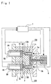
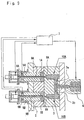
- FIGURE 1 to FIGURE 3 are cross sectional views showing an embodiment of an apparatus for working a method for injection compression molding according to the present invention.
- the apparatus is provided with cavities 1A and 1B filled with molten resin, a movable mold 2, a stationary mold 3, an injection nozzle 4 injecting the molten resin into a mold, movable cores 5A and 5B provided for the cavities 1A and 1B, respectively, pressure sensors 6A and 6B provided at rear ends of the movable cores 5A and 5B for detecting resin pressure in the cavities 1A and 1B,respectively, a controlling unit 7 by which entire operations of the apparatus are controlled, and valve gate type hot runners 10A and 10B (two of specific examples of them are shown in FIG. 4 and FIG. 5) provided for the cavities 1A and 1B, respectively.
- the apparatus for injection compression molding shown in FIG. 1 to FIG. 3 is characterized in that:
- the valve gate type hot runner used in the present invention refers to a runner whose nozzle itself is provided with a heater for preventing the molten resin from temperature decrese, together with a needle valve that can open and close the nozzle gate.
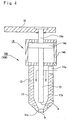
- a first example of the hot runner will be explained with reference to FIG 4.
- the valve gate type hot runner 10A (10B) shown in the figure comprises a hot nozzle 11, a heater 12, a needle valve 13, an actuator 14, and limit bar 15, with the actuator 14 comprising a piston 14a, a cylinder chamber 14b and a piston rod 14c.
- the molten resin is charged from an inlet 11a of the hot nozzle 11, flows through a bore 11b and is injected from a gate 11c at the top into the cavity to fill it.
- the tip of the needle valve 13 is halted at a position "a" in the nozzle 11 to make the gate 11c in an opened state that allows the molten resin to easily flow into the cavity as shown in Fig. 4.
- the actuator 14 is actuated to advance the tip of the needle valve 13 to a position "b" near the top end of the hot nozzle 11. This allows the gate 11c to be completely closed.
- the limit bar 15 provided at the upper end of the piston rod 14c is made stopped by a stopper omitted from the figure during the period of closing the mold so that the tip of the needle valve 13 is not advanced (lowered) over the position "b".
- FIG 5 there is shown a second example of the valve gate type hot runner.
- a gate opening and closing section is not positioned near the cavity so that the molten resin with a volume of at least one shot can be reserved between the gate opening and closing section and the cavity while being kept in heated and molten state.
- the gate opening and closing section is positioned apart from the cavity. This allows the molten resin with a volume equal to or more than one shot, which are reserved in the bore 11b, to be injected into the cavity to fill it without being affected by merging of the molten resin flow at the tip of the needle valve 13. Therefore, molded products requiring superior optical characteristics can be produced without optical characteristics thereof being deteriorated.
- FIGURE 6 is an example of a timing chart showing relationships between time and the states of the molding process, core position, cavity inner pressure, core pressure, and valve gate in carrying out the method for injection compression molding according to the present invention using the apparatus for injection compression molding shown in FIGS. 1 to 3.
- FIGURE 7 is a block diagram showing an example of the controlling unit 7.
- the controlling unit 7 comprises an input signal processor 7a with a process card 71 and I/O card 72, and an controlling output signal sending processor 7b with a process card 73 and I/O card 74.
- the input signal processor 7a there are given outputs of the pressure sensors 6A and 6B, and those of pressure sensors 6A' and 6B' provided at other positions as will be described later, or an output of a position detection sensor 6C used in still another embodiment shown in FIGS. 12A to 12D or FIGS. 14A to 14E.
- the outputs of the controlling output signal sending processor 7a are sent to servo valves 5a and 5b of cylinders for respectively driving the movable cores 5A and 5B, to servo valves 10a and 10b of valve gate cylinders for respectively driving needle valves 13A and 13B of the valve gate type hot runners 10A and 10B, and to servo valves 9a and 9b of punch cylinders for driving punches 9A and 9B in another embodiment shown in FIGS. 8 to 10.
- the resin being molten and plasticized at an injection molding machine is distributed from the injection nozzle 4 to the valve gate type hot runners 10A and 10B through respective flow distribution passages 3a and 3b formed in the stationary mold 3 for filling cavities 1A and 1B through respective gates at top ends of the runners (see FIG. 1).
- the pressures inside the cavities 1A and 1B are detected by the pressure sensors 6A and 6B provided at the rear ends of the movable cores 5A and 5B provided for the cavities, respectively, so as to transmit the outputs of the sensors to the controlling unit 7.
- each of the pressure sensors 6A and 6B is of using a strain gage for detecting the resin pressure in the cavity as a strain of the core, which is calibrated for being detected as a pressure.
- the pressure sensors are preferably provided at positions 6A' and 6B' shown in FIG. 1 because the resin pressures in the cavities can be directly detected there.
- a pressure sensor of a piezoelectric element in which a pressure is detected by calibrating a voltage generated when force is applied to quartz, is more preferable than that of a strain gage because of its smaller mounting space and its higher accuracy.
- the controlling unit 7 Let the pressure of the cavity 1A first reach a specified one when the cavities 1A and 1B are fully filled to raise the pressure of the resin. This allows the controlling unit 7 to transmit a signal to a driving unit (the servo valve 10a of the valve gate cylinder in FIG. 7) of the valve gate type hot runner 10A for the cavity 1A. The driving unit then shifts the needle valve 13A thereof to the gate side as shown in FIG. 2 for completely closing the gate.
- a driving unit the servo valve 10a of the valve gate cylinder in FIG. 7
- the movable core 5A is made advanced into the cavity 1A to compress the molten resin in the cavity to unify the pressure distribution in the cavity.
- the resin in the cavity 1A is compressed until the pressure thereof reaches the other specified value.
- the controlling unit 7 transmits a signal to a driving unit (the servo valve 10b of the valve gate cylinder in FIG. 7) of the valve gate type hot runner 10B for the cavity 1B like in the above.
- the driving unit then shifts the needle valve 13B thereof to the gate side as shown in FIG 3 for completely closing the gate.
- the movable core 5B is made advanced into the cavity 1B to compress the molten resin in the cavity to unify the pressure distribution in the cavity.
- the resin in the cavity 1B is compressed until the pressure thereof reaches the other specified value.
- each of the detected values for controlling the movable cores and valve gate type hot runners is scanned with a scanning time of 2msec or less, preferably of 1msec or less, and further preferably, of 500 ⁇ sec or less.
- such operations each being independently carried out for each of the cavities 1A and 1B, can provide the same shape of pressure behavior between the cavity 1A and cavity 1B after being completely filled with the resin.
- a graph showing behavior in pressure in each of the cavities 1A and 1B, the maximum pressure and the period of holding the pressure in each of the cavities can be made to be the same to the other.
- the embodiment is shown as two-cavity molding in the drawings. However, the number can be further increased by increasing the number of cavities and, in compliance with this, the number of the valve gate hot runners and movable cores.
- gears of the second grade of JIS or impellers at present produced by single-cavity molding with core compression molding, by four-cavity molding.
- optical disks such as CD-Rs, DVDs and DVD-Rs
- optical disks such as CD-Rs, DVDs and DVD-Rs
- single-cavity molding with whole parting area compression molding adopted two to four-cavities molding also becomes possible by adopting the method for core compression molding according to the present invention.
- FIGS. 8 to 10 Next, another embodiment shown in FIGS. 8 to 10 will be explained.
- the embodiment differs from that shown in FIGS. 1 to 3 in that, while the hot runner of valve gate type is used for opening and closing the gate in the embodiment shown in FIGS. 1 to 3, the gate of the hot runner in the embodiment shown in FIGS. 8 to 10 is constituted to be opened and closed by a punch which advances and retreats in the cavity toward and from the gate without using the valve gate type hot runner.
- reference numerals and characters 10A and 10B denote hot runners provided for the cavities 1A and 1B for which gates 8A and 8B opened and closed by punches 9A and 9B are provided, respectively.
- Other elements denoted with the same reference numerals and characters are the same or equivalent elements shown in FIGS. 1 to 3.
- FIGURE 11 is an example of a timing chart showing relationships between time and the states of the molding process, core position, cavity inner pressure, core pressure, and punch in carrying out the method for injection compression molding according to the present invention using the apparatus for injection compression molding shown in FIGS. 8 to 10.
- the resin being molten and plasticized at an injection molding machine is first distributed from the injection nozzle 4 to the valve gate type hot runners 10A and 10B through respective flow distribution passages 3a and 3b formed in the stationary mold 3 for filling cavities 1A and 1B through respective gates 8A and 8B at top ends of the runners, respectively (see FIG. 8).
- the pressures inside the cavities 1A and 1B are detected by the pressure sensors 6A and 6B provided at the rear ends of the movable cores 5A and 5B provided for the cavities, respectively, so as to transmit the outputs of the sensors to the controlling unit 7.
- the pressure sensors of the same kind as that used in the previous embodiment in which the valve gate are used are mounted at the same positions as those in the previous embodiment.
- the controlling unit 7 Let the pressure of the cavity 1A first reach a specified one when the cavities 1A and 1B are fully filled to raise the pressure of the resin therein. This allows the controlling unit 7 to transmit a signal to a driving unit (the servo valve 9a of the punch cylinder in FIG 7) of the punch 9A for the cavity 1A. The driving unit then shifts the punch 9A to the side of the gate 8A as shown in FIG. 9 for completely closing the gate 8A.
- the movable core 5A is made advanced into the cavity 1A to compress the molten resin in the cavity to unify the pressure distribution in the cavity.
- the resin in the cavity 1A is compressed until the pressure thereof reaches the other specified value.
- the controlling unit 7 transmits a signal to a driving unit (the servo valve 9b of the punch cylinder in FIG. 7) of the punch 9B for the cavity 1B like in the above.
- the driving unit shifts the punch 9B to the side of the gate 8B as shown in FIG 10 for completely closing the gate 8B.
- the movable core 5B is made advanced into the cavity 1B to compress the molten resin in the cavity to unify the pressure distribution in the cavity.
- the resin in the cavity 1B is compressed until the pressure thereof reaches the other specified value.
- each of the respective detected values for controlling the movable cores and punches is scanned with a scanning time of 2msec or less, preferably of 1msec or less, and further preferably, of 500 ⁇ sec or less.
- Such operations each being independently carried out for each of the cavities 1A and 1B, can provide the same shape of pressure behavior between the cavity 1A and cavity 1B after being completely filled with the resin like in the previous embodiment shown in FIGS. 1 to 3.
- the resin filled-state in each of the cavities is judged to be proper or improper by individually detecting the pressure in the cavity.
- the pressure in the cavity often behaviors with time by contamination in the mold or other areas to be sometimes not necessarily suitable as judging means for the resin-filled state of the cavity.
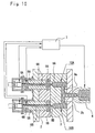
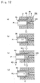
- FIGS. 12A to 12D and FIGS. 14A to 14E is constituted so as to judge the resin-filled state in a cavity by a position of the movable core in the cavity.
- FIGS. 12A to 12D and FIG 14A to 14E the embodiment of the apparatus is shown with examples of operations of filling one cavity with resin illustrated in successive steps. However, the same operations are individually carried out independently about a plurality of cavities like in the previous embodiments. Furthermore, for opening and closing the gate, instead of the valve gate type hot runner shown in each figure, the punch as shown in FIG. 8 to FIG 10 can be used.
- reference numeral and character 1A denotes the cavity provided in the movable mold 2, which is also provided with the movable core 5A.
- Reference numeral 3 denotes the stationary mold in which there is provided the valve gate type hot runner 10A with the needle valve 13A therein.
- Reference character PL denotes the parting line.
- FIGURE 13 is an example of a timing chart showing relationships between time and the states of the molding process, core position, cavity inner pressure, core pressure, and valve gate in carrying out the injection compression molding according to this example.
- a top end 5A-1 of the retreating movable core 5A reaches the specified position C determined beforehand (that is, when the cavity is filled with a specified volume of resin necessary for producing a molded product) as shown in FIG. 12C, this is detected to actuate the needle valve 13A of the valve gate type hot runner 10A for closing the runner gate.
- the rear end of the movable core 5A is detected by a sensor 6C at a specified position C' outside the cavity, or a specified position of the movable core 5A is detected at a specified position in the driving unit of the core 5A, for example. From the result of the detection, the position of the top end of the core can be obtained.
- any known position detection means such as an encoder or a limit switch can be applied.
- the resolution of the position detection sensor is taken to be 5 ⁇ m or less, preferably, 1 ⁇ m or less, and further preferably, 0.5 ⁇ m or less.
- the sampling time of the detected value of the position sensor is taken to be 1msec or less, preferably, 50 ⁇ sec or less, and further preferably, 25 ⁇ sec or less.
- each of the respective detected values for controlling the movable cores and valve gate type hot runners is scanned with a scanning time of 2msec or less, preferably of 1msec or less, and further preferably, of 500 ⁇ sec or less.
- the pressure P2 is applied to the movable core 5A as shown in FIG. 12D to raise the resin pressure in the cavity for carrying out compression molding, and then, the resin in the cavity is cooled to be hardened with the resin pressure in the cavity being kept raised.
- the above operation is independently carried out for each of the cavities.
- the mold is opened and the molded products are ejected.
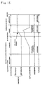
- FIG. 15 shows an example of a timing chart therefor.
- FIG. 15 there are shown relationships between time and the states of the molding process, core position, cavity inner pressure, core pressure, and valve gate in carrying out the injection compression molding according to this example.
- the movable core 5A is made retreated to the position D farther than the position C to which the movable core is retreated when the cavity 1A is filled with a specified volume of resin. This allows the resin to fill the cavity with a volume more than the specified one necessary for producing a molded product as shown in FIG 14B.
- the cavity filled with excessive resin will generate too much pressure, so that the cavity may be filled beforehand with a sparing amount of the excessive resin which is also made to flow back by the movable core 5A pushed back into the cavity.
- the pressure in the cavity may be detected for closing the gate.
- the pressure P2 is applied to the movable core 5A as shown in FIG 14E to raise the resin pressure in the cavity for carrying out compression molding, and then, the resin in the cavity is cooled to be hardened with the resin pressure in the cavity being kept raised.
- the above operation is independently carried out for each of the cavities.
- the mold is opened and the molded products are ejected.
- the molded products can be produced accurately by the multi-cavity molding.
- the variation in characteristics of the molded products such as density becomes smaller in order of the marks shown as ⁇ , o, and oo, namely, ⁇ >> o > oo. Therefore, the method based on the detection of pressure in the cavity is preferable for controlling the resin-filled state. Further, the method of detecting the position of the movable core is more preferable for carrying out the control.
- the resin-filled state of each of the cavities is individually detected to individually close each gate for allowing compression injection molding to be independently carried out in each of the cavity. Consequently, the method for injection compression molding and the apparatus for working the method can be provided in which multi-cavity molding of high-precision molded products can be carried out speedily and efficiently with a relatively simple apparatus without any delay due to a controlling operation of a regulating valve of a runner section in resin injection operation.
Landscapes
- Engineering & Computer Science (AREA)
- Manufacturing & Machinery (AREA)
- Mechanical Engineering (AREA)
- Moulds For Moulding Plastics Or The Like (AREA)
- Injection Moulding Of Plastics Or The Like (AREA)
Abstract
With an object of providing a method for injection compression molding and
an apparatus for working the method which can speedily and efficiently carry out
multi-cavity molding of high-precision molded products, the method according to the
present invention is characterized by carrying out in order a process comprising the
steps of providing a mold comprising a movable mold and a stationary mold, and being
provided with a plurality of cavities each being provided with a movable core and a hot
runner through which a distributed flow of molten resin is supplied to the cavities;
closing the mold (2, 3); then supplying the molten resin to fill a plurality of the cavities
(1A, 1B) provided in the mold while making the molten resin distributed to flow
through the hot runners (10A, 10B) provided for respective cavities; individually
detecting a resin-filled state in each cavity; when the resin-filled state in the cavity is
detected to become in a specified state, individually closing a gate of the cavity
completely; individually advancing a top of the movable core (5A, 5B) into the cavity
to individually raise a pressure in the cavity up to a specified value; and ejecting
molded products after a specified cooling time.
Description
The present invention relates to a method for injection compression molding
and an apparatus for working the method, more particularly to a method for a so-called
multi-cavity injection compression molding and an apparatus for working the method.
In injection molding as one of plastics molding methods, hot plastic resin,
molten, mixed and milled in a molding machine, is poured in a molding space (cavity)
in a mold for being cooled and hardened in the mold to be provided as plastics in a
specified form.
In the injection molding, multi-cavity molding is a common practice for
obtaining high productivity, in which resin is injected into a plurality of cavities at one
time to be produced as a plurality of molded products. About a process of filling each
of the cavities with resin in such multi-cavity molding, observation with short molded
products or a visualized mold proves that there is a variation in a filling time of each of
cavities such that the resin fills the cavities unevenly.
The resin filling the cavities shrinks when cooled by the mold. Therefore,
further resin is supplied into the cavity by the molding machine with application of a
holding pressure so as to compensate the shrinkage. In the multi-cavity molding,
variation among amounts of the resin filling the cavities causes pressure differences
among the cavities that provide different shrinkage factors which results in difference
in dimensional accuracy among the molded products.
While, injection and compression molding is adopted in producing optical
discs such as CD-Rs, DVDs, DVD-Rs for which high dimensional accuracy is required,
or high precision plastic mechanical parts such as precision gears above the second
grade of JIS (Japanese Industrial Standards), compressor valves or impellers. The
molding method therefor is basically the same as conventional injection molding.
However, with additional compression operation to the mold, it provides better molded
products with reduced distortion together with improved replication characteristics and
optical characteristics.
There are two types of applying compression to a mold, i.e. a whole parting
area compression type and a core compression type. In the whole parting area type, a
mold with socket and spigot structure is used in which movable mold is controlled by
mold clamping pressure for applying the compression. In the core compression type,
an independent pressurizing unit is provided on the movable mold for pressurizing the
cavity by a movable component part provided in the mold.
The present invention can be preferably applied to the latter method.
In conventional injection compression molding, every cavity is still
compressed at a time even in carrying out multi-cavity molding to make it impossible
to eliminate variation among in molded products due to the resin unevenly filling the
cavities, which was liable to cause variation in accuracy of the molded products.
Therefore, single-cavity molding is still dominant even at present for the high precision
molded products as above even by the injection compression molding, while molding
with two or more cavities inevitably lowers dimensional accuracy with an increase in
the number of cavities.
A specific example of a mold for the injection compression molding aiming
at the multi-cavity molding is shown as the one described in JP-A-61-125824, for
example.
The mold in the above example is, in addition to pressurizing cylinders for
driving a plurality of movable inserts together which are provided in a plurality of
cavities, respectively, provided with supplementary fine adjustment pressurizing
cylinders for individually driving the respective movable inserts. Each of the movable
inserts is thus finely adjusted while being driven to eliminate differences among
conditions of the filled cavities. Namely, a pressure in each of the cavities is detected
by a pressure sensor provided in each of resin wells so as to control pressurizing force
of each of the fine adjustment pressurizing cylinders on the basis of detected values.
However, in such a plurality of the cavities, communicating with one another
through a gate each other, variation in conditions of the cavities due to unevenly
supplied resin is not so completely eliminated even by the independent pressurization
that variation is still found in accuracy'of the molded products. Furthermore, there is
come time-lag in behavior in resin pressure between the cavity and the resin well
provided outside the cavity for resin pressure detection. This causes a problem of
making it difficult to speedily and accurately pressurize the resin.
Another specific example of an apparatus for the injection compression
molding aiming at the multi-cavity molding is shown as the one described in JP-A-61-211012.
The apparatus has, in addition to the independent fine adjustment control
mechanism of the movable insert in the mold described in the above JP-A-61-125824,
pressure detecting pins and double-doored regulating valves. Each of the pins and
each of the regulating valves are attached to each of runner sections so as to adjust
supply of the molten resin on the basis of the pressure of each of the resin well.
This makes the control mechanism more complicated than that for the mold
described in the above JP-A-61-125824. The complicated mechanism will cause a
time lag between detected pressure behavior and actual pressure behavior in the cavity
or a delay in resin injection operation due to limited response speed in control operation
of the regulating valve of the runner section. Thus there is presented a problem of
making speedy and accurate operation difficult.
An apparatus for solving the above problems is shown as the invention
described in JP-A-6-208734. The invention proposes to carry out individually in each
of cavities operations of detecting an internal pressure of a mold, sealing a sprue when
the detected pressure reaches a specified value, and compressing the cavity after a
specified time elapsed. In the invention, the resin pressure is detected by a pressure
sensor provided at a rear end of an ejector sleeve. The ejector sleeve and a gate cutter
mechanism in contact with inside the ejector sleeve are both allowed to slide.
Therefore, long-term molding will cause wear that behaviors friction resistance with
time to sometimes result in variation in detected value of pressure.
Moreover, a multi-cavity mold with individually controlled compression
cores is shown as the invention related to JP-A-6-304981. In the invention,
compression cores for plurality of cavities and cut punches for cutting gates are
individually controlled. In the method, however, the compression cores and cut
punches are controlled with reference to elapsed time rather than detection of the state
of the resin in the cavity. This requires many man-hours in determining the optimum
condition of each of the cavities.
Furthermore, in producing molded products requiring superior optical
characteristics such as CD-Rs, DVDs, DVD-Rs, resin flow made merged in a runner
section just before a gate causes a problem of deteriorating optical characteristics of the
molded products.
The present invention was made to solve the above problems with an object
of providing a method for injection compression molding and an apparatus for working
the method by which drawbacks in conventional injection compression molding are
eliminated, multi-cavity molding of high precision molded products can be carried out
speedily and efficiently, molded products requiring superior optical characteristics can
be molded without loss of the optical characteristics thereof, and the apparatus can be
constituted without requiring any complexity.
The above object can be achieved by the parting area compression type mold
to which the present invention is suitably applied, namely, by a method for injection
compression molding of carrying out in order a process comprising the steps of:
The resin-filled state in each cavity can be detected by individually detecting
a pressure in each cavity or by individually detecting a position of the movable cores in
each cavity.
It is recommended that supplying of the resin is started to fill the cavity
therewith with a specified pressure applied to each of the movable cores beforehand to
advance the movable cores to a parting line side and, when each of the movable cores,
being gradually retreated against the above pressure as the cavity is being filled with
the resin, comes at a specified position, the gate is completely closed.
It is also recommended that a volume of resin more than a specified volum is
supplied to fill the cavity, the movable core is thereafter pressed into the cavity to allow
a part of the resin to flow back through the gate, and the gate is completely closed when
a top end of the movable core comes at the specified position in the process.
In the hot runner of a valve gate type, the gate is opened and closed by the
valve thereof, while in the hot runner not of a valve gate type, it is recommended that
the gate is opened and closed by a punch advancing and retreating in the cavity toward
and from the gate.
The method for injection compression molding according to the present
invention can be suitably carried out by an apparatus for injection compression molding
comprising:
the controlling unit carrying out in order controls of closing the mold, individually detecting the resin-filled state in each of the cavities by each of the sensors with the molten resin being supplied from each of the hot runners to fill each of the cavities, individually closing the gate of a cavity in which the resin-filled state in the cavity becomes in a specified state, individually advancing thereafter each of the movable cores into the cavity in the specified resin-filled state to individually raise a pressure in each cavity up to a specified value, and ejecting molded products after a specified cooling time.
In the above apparatus, for the sensor detecting the resin-filled state in each
of the cavities, a pressure sensor can be used which detects a pressure in each of the
cavities, or a position sensor can be used which detects a position of the movable core
in each of the cavities, for example.
For the hot runner, a hot runner of a valve gate type can be suitably used.
In particular, in molding molded products for which a superior optical
characteristics are required, it is recommended to use a valve gate type hot runner in
which a gate opening and closing section is positioned apart from the cavity. Such hot
runner is constituted so that molten resin with a volum equal to or more than one shot is
reserved between the gate opening and closing section and the cavity.
In using a hot runner not of a valve gate type, it is recommended that the gate
is provided with a punch advancing and retreating in the cavity toward and from the
gate for being opened and closed.
The present invention will be specifically explained below with reference to
drawings.
FIGURE 1 to FIGURE 3 are cross sectional views showing an embodiment
of an apparatus for working a method for injection compression molding according to
the present invention. The apparatus is provided with cavities 1A and 1B filled with
molten resin, a movable mold 2, a stationary mold 3, an injection nozzle 4 injecting the
molten resin into a mold, movable cores 5A and 5B provided for the cavities 1A and
1B, respectively, pressure sensors 6A and 6B provided at rear ends of the movable cores
5A and 5B for detecting resin pressure in the cavities 1A and 1B,respectively, a
controlling unit 7 by which entire operations of the apparatus are controlled, and valve
gate type hot runners 10A and 10B (two of specific examples of them are shown in FIG.
4 and FIG. 5) provided for the cavities 1A and 1B, respectively.
The apparatus for injection compression molding shown in FIG. 1 to FIG. 3 is
characterized in that:
The valve gate type hot runner used in the present invention refers to a runner
whose nozzle itself is provided with a heater for preventing the molten resin from
temperature decrese, together with a needle valve that can open and close the nozzle
gate. A first example of the hot runner will be explained with reference to FIG 4.
The valve gate type hot runner 10A (10B) shown in the figure comprises a
hot nozzle 11, a heater 12, a needle valve 13, an actuator 14, and limit bar 15, with the
actuator 14 comprising a piston 14a, a cylinder chamber 14b and a piston rod 14c.
The molten resin is charged from an inlet 11a of the hot nozzle 11, flows
through a bore 11b and is injected from a gate 11c at the top into the cavity to fill it.
During the filling period with the resin, the tip of the needle valve 13 is
halted at a position "a" in the nozzle 11 to make the gate 11c in an opened state that
allows the molten resin to easily flow into the cavity as shown in Fig. 4.
After the molten resin has filled the cavity in this way to make the cavity
satisfy a specified filled state, the actuator 14 is actuated to advance the tip of the
needle valve 13 to a position "b" near the top end of the hot nozzle 11. This allows
the gate 11c to be completely closed.
In the example shown in the figure, the limit bar 15 provided at the upper end
of the piston rod 14c is made stopped by a stopper omitted from the figure during the
period of closing the mold so that the tip of the needle valve 13 is not advanced
(lowered) over the position "b".
In FIG 5, there is shown a second example of the valve gate type hot runner.
In the example, a gate opening and closing section is not positioned near the cavity so
that the molten resin with a volume of at least one shot can be reserved between the
gate opening and closing section and the cavity while being kept in heated and molten
state.
In the valve gate type hot runner with such form, the gate opening and
closing section is positioned apart from the cavity. This allows the molten resin with a
volume equal to or more than one shot, which are reserved in the bore 11b, to be
injected into the cavity to fill it without being affected by merging of the molten resin
flow at the tip of the needle valve 13. Therefore, molded products requiring superior
optical characteristics can be produced without optical characteristics thereof being
deteriorated.
FIGURE 6 is an example of a timing chart showing relationships between
time and the states of the molding process, core position, cavity inner pressure, core
pressure, and valve gate in carrying out the method for injection compression molding
according to the present invention using the apparatus for injection compression
molding shown in FIGS. 1 to 3. FIGURE 7 is a block diagram showing an example of
the controlling unit 7.
In FIG. 7, the controlling unit 7 comprises an input signal processor 7a with a
process card 71 and I/O card 72, and an controlling output signal sending processor 7b
with a process card 73 and I/O card 74. To the input signal processor 7a, there are
given outputs of the pressure sensors 6A and 6B, and those of pressure sensors 6A' and
6B' provided at other positions as will be described later, or an output of a position
detection sensor 6C used in still another embodiment shown in FIGS. 12A to 12D or
FIGS. 14A to 14E. The outputs of the controlling output signal sending processor 7a
are sent to servo valves 5a and 5b of cylinders for respectively driving the movable
cores 5A and 5B, to servo valves 10a and 10b of valve gate cylinders for respectively
driving needle valves 13A and 13B of the valve gate type hot runners 10A and 10B, and
to servo valves 9a and 9b of punch cylinders for driving punches 9A and 9B in another
embodiment shown in FIGS. 8 to 10.
In carrying out injection compression molding with the apparatus shown in
FIGS. 1 to 3, the resin being molten and plasticized at an injection molding machine is
distributed from the injection nozzle 4 to the valve gate type hot runners 10A and 10B
through respective flow distribution passages 3a and 3b formed in the stationary mold 3
for filling cavities 1A and 1B through respective gates at top ends of the runners (see
FIG. 1).
At this time, supply of the filling resin is started with the movable cores 5A
and 5B being advanced onto the parting line side with a specified pressure P1 applied
thereto beforehand at a pre-stage of injection. As each of the cavities 1A and 1B is
gradually filled with the resin with the inner pressure thereof raised up to the P1 or
above, the movable cores 5A and 5B gradually retreat due to the pressure forces.
In order to judge whether or not the cavities 1A and 1B are sufficiently filled
with the resin, the pressures inside the cavities 1A and 1B are detected by the pressure
sensors 6A and 6B provided at the rear ends of the movable cores 5A and 5B provided
for the cavities, respectively, so as to transmit the outputs of the sensors to the
controlling unit 7.
Specifically, for example, each of the pressure sensors 6A and 6B is of using
a strain gage for detecting the resin pressure in the cavity as a strain of the core, which
is calibrated for being detected as a pressure. As for molded products each with an
imprint of the pressure sensor safely left thereon, the pressure sensors are preferably
provided at positions 6A' and 6B' shown in FIG. 1 because the resin pressures in the
cavities can be directly detected there. At this time, a pressure sensor of a
piezoelectric element, in which a pressure is detected by calibrating a voltage generated
when force is applied to quartz, is more preferable than that of a strain gage because of
its smaller mounting space and its higher accuracy.
Let the pressure of the cavity 1A first reach a specified one when the cavities
1A and 1B are fully filled to raise the pressure of the resin. This allows the
controlling unit 7 to transmit a signal to a driving unit (the servo valve 10a of the valve
gate cylinder in FIG. 7) of the valve gate type hot runner 10A for the cavity 1A. The
driving unit then shifts the needle valve 13A thereof to the gate side as shown in FIG. 2
for completely closing the gate.
Then, the movable core 5A is made advanced into the cavity 1A to compress
the molten resin in the cavity to unify the pressure distribution in the cavity. At the
same time, the resin in the cavity 1A is compressed until the pressure thereof reaches
the other specified value.
Next to this, when the pressure of the cavity 1B reaches a specified one, the
controlling unit 7 transmits a signal to a driving unit (the servo valve 10b of the valve
gate cylinder in FIG. 7) of the valve gate type hot runner 10B for the cavity 1B like in
the above. The driving unit then shifts the needle valve 13B thereof to the gate side as
shown in FIG 3 for completely closing the gate. Along with this, the movable core
5B is made advanced into the cavity 1B to compress the molten resin in the cavity to
unify the pressure distribution in the cavity. At the same time, the resin in the cavity
1B is compressed until the pressure thereof reaches the other specified value.
In this case, each of the detected values for controlling the movable cores and
valve gate type hot runners, is scanned with a scanning time of 2msec or less,
preferably of 1msec or less, and further preferably, of 500µsec or less.
In the present invention, such operations, each being independently carried
out for each of the cavities 1A and 1B, can provide the same shape of pressure behavior
between the cavity 1A and cavity 1B after being completely filled with the resin.
Namely, according to the present invention, as shown in FIG 16, a graph
showing behavior in pressure in each of the cavities 1A and 1B, the maximum pressure
and the period of holding the pressure in each of the cavities can be made to be the
same to the other. With such application of pressure to the resin in a definite period
and cooling of the resin by the mold, the resin is hardened to be obtained as high
precision molded products without variations in forms and other associated
characteristics.
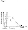
Contrary to this, in the related art, the resin in each of the cavities 1A and 1B is
simultaneously compressed with the other to make the pressure in the cavity 1B
lowered without reaching the maximum pressure of the cavity 1A as shown in FIG 17.
This results in larger shrinkage factor of the molded product after being molded in the
cavity 1B than that of the molded product in the cavity 1A to cause variation in
dimensions of final products.
The embodiment is shown as two-cavity molding in the drawings. However,
the number can be further increased by increasing the number of cavities and, in
compliance with this, the number of the valve gate hot runners and movable cores.
According to the present invention, it becomes possible to produce gears of
the second grade of JIS or impellers, at present produced by single-cavity molding with
core compression molding, by four-cavity molding.
Moreover, as for optical disks such as CD-Rs, DVDs and DVD-Rs, at present
produced by single-cavity molding with whole parting area compression molding
adopted, two to four-cavities molding also becomes possible by adopting the method
for core compression molding according to the present invention.
Next, another embodiment shown in FIGS. 8 to 10 will be explained.
The embodiment differs from that shown in FIGS. 1 to 3 in that, while the hot
runner of valve gate type is used for opening and closing the gate in the embodiment
shown in FIGS. 1 to 3, the gate of the hot runner in the embodiment shown in FIGS. 8
to 10 is constituted to be opened and closed by a punch which advances and retreats in
the cavity toward and from the gate without using the valve gate type hot runner.
In FIGS. 8 to 10, reference numerals and characters 10A and 10B denote hot
runners provided for the cavities 1A and 1B for which gates 8A and 8B opened and
closed by punches 9A and 9B are provided, respectively. Other elements denoted with
the same reference numerals and characters are the same or equivalent elements shown
in FIGS. 1 to 3.
FIGURE 11 is an example of a timing chart showing relationships between
time and the states of the molding process, core position, cavity inner pressure, core
pressure, and punch in carrying out the method for injection compression molding
according to the present invention using the apparatus for injection compression
molding shown in FIGS. 8 to 10.
Like in the embodiment explained above, the resin being molten and
plasticized at an injection molding machine is first distributed from the injection nozzle
4 to the valve gate type hot runners 10A and 10B through respective flow distribution
passages 3a and 3b formed in the stationary mold 3 for filling cavities 1A and 1B
through respective gates 8A and 8B at top ends of the runners, respectively (see FIG. 8).
At this time, supply of the filling resin is started with the movable cores 5A
and 5B being advanced onto the parting line side with a specified pressure P1 applied
thereto beforehand at a pre-stage of injection. As each of the cavities 1A and 1B is
gradually filled with the resin with the inner pressure thereof raised up to the P1 or
above, the movable cores 5A and 5B to gradually retreat due to the pressure forces.
The pressures inside the cavities 1A and 1B are detected by the pressure
sensors 6A and 6B provided at the rear ends of the movable cores 5A and 5B provided
for the cavities, respectively, so as to transmit the outputs of the sensors to the
controlling unit 7. The pressure sensors of the same kind as that used in the previous
embodiment in which the valve gate are used are mounted at the same positions as
those in the previous embodiment.
Let the pressure of the cavity 1A first reach a specified one when the cavities
1A and 1B are fully filled to raise the pressure of the resin therein. This allows the
controlling unit 7 to transmit a signal to a driving unit (the servo valve 9a of the punch
cylinder in FIG 7) of the punch 9A for the cavity 1A. The driving unit then shifts the
punch 9A to the side of the gate 8A as shown in FIG. 9 for completely closing the gate
8A.
Then, the movable core 5A is made advanced into the cavity 1A to compress
the molten resin in the cavity to unify the pressure distribution in the cavity. At the
same time, the resin in the cavity 1A is compressed until the pressure thereof reaches
the other specified value.
Next to this, when the pressure of the cavity 1B reaches a specified one, the
controlling unit 7 transmits a signal to a driving unit (the servo valve 9b of the punch
cylinder in FIG. 7) of the punch 9B for the cavity 1B like in the above. The driving
unit shifts the punch 9B to the side of the gate 8B as shown in FIG 10 for completely
closing the gate 8B. Along with this, the movable core 5B is made advanced into the
cavity 1B to compress the molten resin in the cavity to unify the pressure distribution in
the cavity. At the same time, the resin in the cavity 1B is compressed until the
pressure thereof reaches the other specified value.
In this case, each of the respective detected values for controlling the
movable cores and punches, is scanned with a scanning time of 2msec or less,
preferably of 1msec or less, and further preferably, of 500µsec or less.
Such operations, each being independently carried out for each of the cavities
1A and 1B, can provide the same shape of pressure behavior between the cavity 1A and
cavity 1B after being completely filled with the resin like in the previous embodiment
shown in FIGS. 1 to 3.
In the previous embodiments, the resin filled-state in each of the cavities is
judged to be proper or improper by individually detecting the pressure in the cavity.
However, the pressure in the cavity often behaviors with time by contamination in the
mold or other areas to be sometimes not necessarily suitable as judging means for the
resin-filled state of the cavity.
To provide the pressure sensor at the rear end of a sliding section is often
found to be unsuitable because friction resistance of the sliding section is behaviord
with time by the influence of wear or lubrication to behavior the detected value of the
resin pressure in the cavity. To provide the pressure sensor directly in the cavity is
also often unsuitable because an imprint of the pressure sensor is left on molded
products, and a little difference in position of the sensor provided in each cavity
sometimes causes difference between pressure detection values.
For solving such problems, still another embodiment of the apparatus
according to the present invention shown in FIGS. 12A to 12D and FIGS. 14A to 14E is
constituted so as to judge the resin-filled state in a cavity by a position of the movable
core in the cavity.
In FIGS. 12A to 12D and FIG 14A to 14E, the embodiment of the apparatus
is shown with examples of operations of filling one cavity with resin illustrated in
successive steps. However, the same operations are individually carried out
independently about a plurality of cavities like in the previous embodiments.
Furthermore, for opening and closing the gate, instead of the valve gate type hot runner
shown in each figure, the punch as shown in FIG. 8 to FIG 10 can be used.
An example of the operation for filling the cavity with resin as shown in
FIGS. 12A to 12D will be first explained.
In the figure, reference numeral and character 1A denotes the cavity provided
in the movable mold 2, which is also provided with the movable core 5A. Reference
numeral 3 denotes the stationary mold in which there is provided the valve gate type
hot runner 10A with the needle valve 13A therein. Reference character PL denotes the
parting line.
FIGURE 13 is an example of a timing chart showing relationships between
time and the states of the molding process, core position, cavity inner pressure, core
pressure, and valve gate in carrying out the injection compression molding according to
this example.
Supply of the filling resin from the valve gate type hot runner 10A into the
cavity 1A is started with the movable core 5A being advanced onto the parting line PL
side with a specified pressure P1 applied thereto beforehand at a pre-stage of injection
as shown in FIG. 12A.
As each of the cavities 1A is gradually filled with the resin with the inner
pressure thereof raised up to the P1 or above, the movable cores 5A gradually retreat as
shown in FIG. 12B due to the pressure forces.
When a top end 5A-1 of the retreating movable core 5A reaches the specified
position C determined beforehand (that is, when the cavity is filled with a specified
volume of resin necessary for producing a molded product) as shown in FIG. 12C, this
is detected to actuate the needle valve 13A of the valve gate type hot runner 10A for
closing the runner gate. For detecting that the top end 5A-1 of the movable core 5A
reaches the specified position C in the cavity, the rear end of the movable core 5A is
detected by a sensor 6C at a specified position C' outside the cavity, or a specified
position of the movable core 5A is detected at a specified position in the driving unit of
the core 5A, for example. From the result of the detection, the position of the top end
of the core can be obtained. To such a position detection sensor, any known position
detection means such as an encoder or a limit switch can be applied.
In this case, the resolution of the position detection sensor is taken to be 5µm
or less, preferably, 1µm or less, and further preferably, 0.5µm or less. In addition, the
sampling time of the detected value of the position sensor is taken to be 1msec or less,
preferably, 50µsec or less, and further preferably, 25µsec or less.
In this case, each of the respective detected values for controlling the
movable cores and valve gate type hot runners, is scanned with a scanning time of
2msec or less, preferably of 1msec or less, and further preferably, of 500µsec or less.
After the gate is closed, the pressure P2 is applied to the movable core 5A as
shown in FIG. 12D to raise the resin pressure in the cavity for carrying out compression
molding, and then, the resin in the cavity is cooled to be hardened with the resin
pressure in the cavity being kept raised.
The above operation is independently carried out for each of the cavities.
When the resin in all of the cavities is hardened, the mold is opened and the molded
products are ejected.
Next, another example of the operation for filling the cavity with resin in the
apparatus according to the above embodiment will be explained with reference to FIGS.
14A to 14E together with FIG. 15 showing an example of a timing chart therefor. In
FIG. 15, there are shown relationships between time and the states of the molding
process, core position, cavity inner pressure, core pressure, and valve gate in carrying
out the injection compression molding according to this example.
As shown in FIG. 14A, the movable core 5A is made retreated to the position
D farther than the position C to which the movable core is retreated when the cavity 1A
is filled with a specified volume of resin. This allows the resin to fill the cavity with a
volume more than the specified one necessary for producing a molded product as
shown in FIG 14B.
Following this, as shown in FIG. 14C, a pressure P3, higher than the injection
pressure given from the hot runner, is applied to the movable core 5A with the gate
being opened to push the movable core 5A back into the cavity. This allows a part of
the resin filling the cavity to flow back onto the hot runner side through the gate to
make it possible to provide a uniform pressure distribution in the cavity.
The cavity filled with excessive resin will generate too much pressure, so that
the cavity may be filled beforehand with a sparing amount of the excessive resin which
is also made to flow back by the movable core 5A pushed back into the cavity.
In the process of thus pushing the movable core 5A back into the cavity, it is
detected that the volume of the resin in the cavity reaches the specified one, that is, that
the top end of the movable core comes at the position C as shown in FIG. 14D. This
then actuates the needle valve 13A to close the gate of the hot runner.
In the above, instead of detecting the core position, the pressure in the cavity
may be detected for closing the gate.
Like in the previous example, after the gate is closed, the pressure P2 is
applied to the movable core 5A as shown in FIG 14E to raise the resin pressure in the
cavity for carrying out compression molding, and then, the resin in the cavity is cooled
to be hardened with the resin pressure in the cavity being kept raised. The above
operation is independently carried out for each of the cavities. When the resin in all of
the cavities is hardened, the mold is opened and the molded products are ejected.
According to the present invention constituted as described above, the
molded products can be produced accurately by the multi-cavity molding.
An evaluation of qualities of the molded products based on variation in
weight of product by controlling method presents the following results with marks.
The variation in characteristics of the molded products such as density
becomes smaller in order of the marks shown as ×, o, and oo, namely, × >> o > oo.
Therefore, the method based on the detection of pressure in the cavity is preferable for
controlling the resin-filled state. Further, the method of detecting the position of the
movable core is more preferable for carrying out the control.
As explained above, in the present invention, the resin-filled state of each of
the cavities is individually detected to individually close each gate for allowing
compression injection molding to be independently carried out in each of the cavity.
Consequently, the method for injection compression molding and the apparatus for
working the method can be provided in which multi-cavity molding of high-precision
molded products can be carried out speedily and efficiently with a relatively simple
apparatus without any delay due to a controlling operation of a regulating valve of a
runner section in resin injection operation.
It should be understood that the present invention is not limited by the above
embodiments but includes all of modifications thereof that can be easily made on the
basis of the above description by a person skilled in the art without departing from the
spirit and scope of the invention.
Claims (13)
- A method for injection compression molding which comprises carrying out the following process steps in the order indicated:providing a mold comprising a movable mold (2) and a stationary mold (3), and being provided with a plurality of cavities (1A, 1B) each being provided with a movable core (5A, 5B) and a hot runner (10A, 10B) through which a distributed flow of molten resin is supplied to the cavities;closing the mold (2, 3);then supplying the molten resin to fill a plurality of the cavities (1A, 1B) provided in the mold while making the molten resin distributed to flow through the hot runners (10A, 10B) provided for respective cavities;individually detecting a resin-filled state in each cavity;when the resin-filled state in the cavity is detected to become in a specified state, individually closing a gate of the cavity completely;individually advancing a top end of the movable core (5A, 5B) into the cavity to individually raise a pressure in the cavity up to a specified value; andejecting molded products after a specified cooling time.
- A method for injection compression molding as claimed in claim 1 wherein supplying of the resin is started to fill the cavity therewith with a specified pressure (P1) applied to each of the movable cores (5A, 5B) beforehand to advance the movable cores to a parting line (PL) side and, when each of the movable cores (5A, 5B), being gradually retreated against the above pressure (P1) as the cavity is being filled with the resin, comes at a specified position (C), the gate is completely closed.
- A method for injection compression molding as claimed in claim 1 wherein a volume of resin more than a specified volume is supplied to fill the cavity, the movable core (5A, 5B) is thereafter pressed into the cavity to allow a part of the resin to flow back through the gate, and the gate is completely closed when the movable core (5A, 5B) comes at the specified position (C) in the process.
- A method for injection compression molding as claimed in claim 1 wherein the resin-filled state in each cavity is detected by individually detecting a pressure in each cavity.
- A method for injection compression molding as claimed in claim 1 wherein the resin-filled state in each cavity is detected by individually detecting a position of the movable cores (5A, 5B) in each cavity.
- A method for injection compression molding as claimed in any of claims 1 to 5 wherein the hot runner (10A, 10B) is of a valve gate type, by a valve of which the gate is opened and closed.
- A method for injection compression molding as claimed in any of claims 1 to 5 wherein the gate is opened and closed by a punch (9A, 9B) advancing and retreating in the cavity toward and from the gate.
- An apparatus for injection compression molding comprising:a mold comprising a movable mold (2) and a stationary mold (3), the movable mold and the stationary mold being constituted so as to form a plurality of cavities (1A, 1B) when the mold is closed;a plurality of flow distributing passages distributing molten resin injected from an injection nozzle (4);a plurality of hot runners (10A, 10B) each provided in the stationary mold (3) for each of the cavities (1A, 1B) with each of the flow distributing passages connected thereto so that the distributed molten resin is simultaneously supplied to fill a plurality of the cavities (1A, 1B);a plurality of movable cores (5A, 5B) each provided for each of the cavities in the movable mold so as to raise pressure of the molten resin filled in the cavity with a top of the movable core made to advance into the cavity;a plurality of sensors (6A, 6B, 6C) each individually detecting a resin-filled state in each of the cavities; anda controlling unit (7) controlling operations of opening and closing the mold, supplying the molten resin from the injection nozzle, opening and closing a plurality of the gates, and advancing and retreating the movable cores,the controlling unit (7) carrying out in order controls of closing the mold (2, 3), individually detecting the resin-filled state in each of the cavities (1A, 1B) by each of the sensors (6A, 6B, 6C) with the molten resin being supplied from each of the hot runners (10A, 10B) to fill each of the cavities, individually closing the gate of a cavity in which the resin-filled state in the cavity becomes in a specified state, individually advancing thereafter each of the movable cores (5A, 5B) into the cavity in the specified resin-filled state to individually raise a pressure in each cavity up to a specified value, and ejecting molded products after a specified cooling time.
- An apparatus for injection compression molding as claimed in claim 8 wherein the sensor detecting the resin-filled state in each of the cavities is a pressure sensor (6A, 6B) detecting a pressure in each of the cavities.
- An apparatus for injection compression molding as claimed in claim 8 wherein the sensor detecting the resin-filled state in each of the cavities is a position sensor (6A, 6B) detecting a position of the movable core (5A, 5B) in each of the cavities.
- An apparatus for injection compression molding as claimed in any of claims 8 to 10 wherein the hot runner (10A, 10B) is of a valve gate type.
- An apparatus for injection compression molding as claimed in claim 11 wherein a gate opening and closing section in the valve gate type hot runner is positioned apart from the cavity so as to provide a constitution in which molten resin with a volume equal to or more than one shot is reserved between the gate opening and closing section and the cavity.
- An apparatus for injection compression molding as claimed in any of claims 8 to 10 wherein the gate is provided with a punch (9A, 9B) advancing and retreating in the cavity toward and from the gate for being opened and closed.
Applications Claiming Priority (9)
| Application Number | Priority Date | Filing Date | Title |
|---|---|---|---|
| JP9444899 | 1999-04-01 | ||
| JP9444899 | 1999-04-01 | ||
| JP31064299 | 1999-11-01 | ||
| JP31064399 | 1999-11-01 | ||
| JP31064399 | 1999-11-01 | ||
| JP31064299 | 1999-11-01 | ||
| JP2000015806 | 2000-01-25 | ||
| JP2000015806 | 2000-01-25 | ||
| PCT/JP2000/001952 WO2000059705A1 (en) | 1999-04-01 | 2000-03-29 | Injection compression molding method and injection compression molding device for embodying this method |
Publications (1)
| Publication Number | Publication Date |
|---|---|
| EP1108520A1 true EP1108520A1 (en) | 2001-06-20 |
Family
ID=27468222
Family Applications (1)
| Application Number | Title | Priority Date | Filing Date |
|---|---|---|---|
| EP00912915A Withdrawn EP1108520A1 (en) | 1999-04-01 | 2000-03-29 | Injection compression molding method and injection compression molding device for embodying this method |
Country Status (4)
| Country | Link |
|---|---|
| EP (1) | EP1108520A1 (en) |
| CN (1) | CN1297399A (en) |
| TW (1) | TW426599B (en) |
| WO (1) | WO2000059705A1 (en) |
Cited By (4)
| Publication number | Priority date | Publication date | Assignee | Title |
|---|---|---|---|---|
| EP1757427A3 (en) * | 2005-08-27 | 2007-05-02 | Behr GmbH & Co. KG | Injection compression moulding method |
| WO2008084230A3 (en) * | 2007-01-12 | 2009-02-26 | Peter Reginald Clarke | Injection mould and injection moulding method |
| GB2453339A (en) * | 2007-10-02 | 2009-04-08 | Peter Reginald Clarke | Varying volume of a mould cavity in injection moulding apparatus |
| US8017049B2 (en) | 2008-06-20 | 2011-09-13 | Hyundai Motor Company | Apparatus and method for producing resin product |
Families Citing this family (12)
| Publication number | Priority date | Publication date | Assignee | Title |
|---|---|---|---|---|
| GB2371514A (en) * | 2001-01-26 | 2002-07-31 | Coraltech Ltd | Spreading of moulding material |
| MXPA03006664A (en) | 2001-01-26 | 2004-10-15 | Coraltech Ltd | Mould and method for injection-compression moulding. |
| JP5312897B2 (en) * | 2008-10-20 | 2013-10-09 | Towa株式会社 | Compression molding equipment |
| CN101767413A (en) * | 2010-02-11 | 2010-07-07 | 飞毛腿电池有限公司 | Lithium-battery mold and low-pressure injection molding method |
| JP5512574B2 (en) * | 2011-03-09 | 2014-06-04 | 住友重機械工業株式会社 | Injection molding machine |
| CN106273246A (en) * | 2016-08-29 | 2017-01-04 | 潼南县开鑫电子科技有限责任公司 | A kind of injection machine nozzle |
| CN106738674A (en) * | 2016-12-24 | 2017-05-31 | 浙江工商职业技术学院 | A kind of valve element Leave out thread injection mold |
| CN107756733A (en) * | 2017-09-11 | 2018-03-06 | 广东工业大学 | A kind of plastic injection compression precise forming mold and technique |
| JP6834873B2 (en) * | 2017-09-19 | 2021-02-24 | トヨタ自動車株式会社 | Wiring board manufacturing method and manufacturing equipment |
| CN110561685B (en) * | 2019-10-16 | 2024-10-15 | 江苏铁锚玻璃股份有限公司 | Edge wrapping device and edge wrapping method for glass |
| CN112677404A (en) * | 2020-12-26 | 2021-04-20 | 闽江学院 | Controllable pressurizing and heating curing device |
| CN121133023A (en) * | 2025-11-14 | 2025-12-16 | 烟台市欧林科技有限公司 | Injection mold for dual-use water-heated blankets (both hot and cold) |
Family Cites Families (6)
| Publication number | Priority date | Publication date | Assignee | Title |
|---|---|---|---|---|
| JPS61125824A (en) * | 1984-11-22 | 1986-06-13 | Hitachi Ltd | Extruding compression forming metallic mold |
| JPH0661803B2 (en) * | 1989-12-28 | 1994-08-17 | 日精樹脂工業株式会社 | Injection compression molding method and injection compression molding machine |
| JP2649109B2 (en) * | 1991-04-17 | 1997-09-03 | ファナック株式会社 | Injection molding machine |
| JP2804394B2 (en) * | 1991-09-03 | 1998-09-24 | 株式会社名機製作所 | Injection molding machine for perforated plate |
| JPH0716883A (en) * | 1993-06-30 | 1995-01-20 | Toshiba Mach Co Ltd | Controlling method of fill of resin for injection molding and controlling device of fill of resin for executing the same |
| JPH0957794A (en) * | 1995-08-22 | 1997-03-04 | Asahi Chem Ind Co Ltd | Injection compression molding method |
-
2000
- 2000-03-29 WO PCT/JP2000/001952 patent/WO2000059705A1/en not_active Ceased
- 2000-03-29 EP EP00912915A patent/EP1108520A1/en not_active Withdrawn
- 2000-03-29 CN CN 00800469 patent/CN1297399A/en active Pending
- 2000-04-01 TW TW89106180A patent/TW426599B/en not_active IP Right Cessation
Non-Patent Citations (1)
| Title |
|---|
| See references of WO0059705A1 * |
Cited By (12)
| Publication number | Priority date | Publication date | Assignee | Title |
|---|---|---|---|---|
| EP1757427A3 (en) * | 2005-08-27 | 2007-05-02 | Behr GmbH & Co. KG | Injection compression moulding method |
| WO2008084230A3 (en) * | 2007-01-12 | 2009-02-26 | Peter Reginald Clarke | Injection mould and injection moulding method |
| CN101674924A (en) * | 2007-01-12 | 2010-03-17 | 彼得·雷金纳德·克拉克 | Injection mold and injection molding method |
| GB2445547B (en) * | 2007-01-12 | 2010-03-31 | Peter Reginald Clarke | Injection mould and injection moulding method |
| US8114332B2 (en) | 2007-01-12 | 2012-02-14 | Peter Reginald Clarke | Injection moulding method |
| US8419418B2 (en) | 2007-01-12 | 2013-04-16 | Peter Reginald Clark | Injection mould having a varying volume mould cavity |
| GB2453339A (en) * | 2007-10-02 | 2009-04-08 | Peter Reginald Clarke | Varying volume of a mould cavity in injection moulding apparatus |
| WO2009044142A1 (en) * | 2007-10-02 | 2009-04-09 | Peter Reginald Clarke | Injection compression moulding apparatus and injection compression moulding method |
| GB2453339B (en) * | 2007-10-02 | 2010-03-31 | Peter Reginald Clarke | Injection moulding apparatus and injection moulding method |
| GB2468602A (en) * | 2007-10-02 | 2010-09-15 | Peter Reginald Clarke | Injection compression moulding apparatus and injection compression moulding |
| GB2468602B (en) * | 2007-10-02 | 2012-10-17 | Peter Reginald Clarke | Injection compression moulding apparatus and injection compression moulding method |
| US8017049B2 (en) | 2008-06-20 | 2011-09-13 | Hyundai Motor Company | Apparatus and method for producing resin product |
Also Published As
| Publication number | Publication date |
|---|---|
| TW426599B (en) | 2001-03-21 |
| CN1297399A (en) | 2001-05-30 |
| WO2000059705A1 (en) | 2000-10-12 |
Similar Documents
| Publication | Publication Date | Title |
|---|---|---|
| JP4284070B2 (en) | Mold for injection compression molding and molding method using the same | |
| US6767482B2 (en) | Injection compression molding method and injection compression molding machine | |
| WO2000059705A1 (en) | Injection compression molding method and injection compression molding device for embodying this method | |
| US5948327A (en) | Lens injection-compression-molding method | |
| EP0365684B1 (en) | Molding method and molding apparatus by use of injection-compression molding machine | |
| JP3185197B2 (en) | Injection molding method | |
| JP2002067112A (en) | Method and apparatus for injection compression molding for moldings by multi-cavity method | |
| JP3213931B2 (en) | High-pressure injection molding method and high-pressure injection molding die apparatus used in the method | |
| JP2001277315A (en) | Method for injection compression molding and injection compression molding apparatus for executing the method | |
| JP2002355869A (en) | Multi-cavity injection compression molding method for lenses | |
| US4613295A (en) | Molding apparatus with sensor means | |
| JPH09262880A (en) | High-pressure injection molding method and high-pressure injection molding die apparatus used in the method | |
| JP2002103400A (en) | Method and apparatus for injection-compression molding | |
| JPH09239783A (en) | Mold equipment for injection molding | |
| JP2001505833A (en) | Manufacturing method of injection molding | |
| JPH06848A (en) | Stack mold | |
| JP2002166453A (en) | Injection compression molding method for disk-shaped molding, information recording medium, and injection compression molding apparatus | |
| JP2001260195A (en) | Injection compression molding method and injection compression molding apparatus for implementing the method | |
| JPH06208734A (en) | Multi-cavity injection molding equipment | |
| JPH09262882A (en) | Injection molding method and mold device used therefor | |
| JP2003127195A (en) | Injection/compression molding method and device therefor using the same | |
| JPH0857927A (en) | Injection press molding method and apparatus | |
| JP3266900B2 (en) | Injection molding method and injection molding die apparatus used for this method | |
| JPH0939059A (en) | Injection mold equipment | |
| JP2002347059A (en) | Injection molding apparatus, molding method, and resin molded product |
Legal Events
| Date | Code | Title | Description |
|---|---|---|---|
| PUAI | Public reference made under article 153(3) epc to a published international application that has entered the european phase |
Free format text: ORIGINAL CODE: 0009012 |
|
| 17P | Request for examination filed |
Effective date: 20001220 |
|
| AK | Designated contracting states |
Kind code of ref document: A1 Designated state(s): DE FR GB |
|
| STAA | Information on the status of an ep patent application or granted ep patent |
Free format text: STATUS: THE APPLICATION HAS BEEN WITHDRAWN |
|
| 18W | Application withdrawn |
Withdrawal date: 20021112 |