EP1108273B1 - Explosion-proof plug-in connector - Google Patents
Explosion-proof plug-in connector Download PDFInfo
- Publication number
- EP1108273B1 EP1108273B1 EP99953537A EP99953537A EP1108273B1 EP 1108273 B1 EP1108273 B1 EP 1108273B1 EP 99953537 A EP99953537 A EP 99953537A EP 99953537 A EP99953537 A EP 99953537A EP 1108273 B1 EP1108273 B1 EP 1108273B1
- Authority
- EP
- European Patent Office
- Prior art keywords
- plug connector
- arrangement according
- plug
- connector arrangement
- switch means
- Prior art date
- Legal status (The legal status is an assumption and is not a legal conclusion. Google has not performed a legal analysis and makes no representation as to the accuracy of the status listed.)
- Expired - Lifetime
Links
Images


Classifications
-
- H—ELECTRICITY
- H01—ELECTRIC ELEMENTS
- H01R—ELECTRICALLY-CONDUCTIVE CONNECTIONS; STRUCTURAL ASSOCIATIONS OF A PLURALITY OF MUTUALLY-INSULATED ELECTRICAL CONNECTING ELEMENTS; COUPLING DEVICES; CURRENT COLLECTORS
- H01R13/00—Details of coupling devices of the kinds covered by groups H01R12/70 or H01R24/00 - H01R33/00
- H01R13/46—Bases; Cases
- H01R13/52—Dustproof, splashproof, drip-proof, waterproof, or flameproof cases
- H01R13/527—Flameproof cases
-
- H—ELECTRICITY
- H01—ELECTRIC ELEMENTS
- H01R—ELECTRICALLY-CONDUCTIVE CONNECTIONS; STRUCTURAL ASSOCIATIONS OF A PLURALITY OF MUTUALLY-INSULATED ELECTRICAL CONNECTING ELEMENTS; COUPLING DEVICES; CURRENT COLLECTORS
- H01R13/00—Details of coupling devices of the kinds covered by groups H01R12/70 or H01R24/00 - H01R33/00
- H01R13/66—Structural association with built-in electrical component
- H01R13/70—Structural association with built-in electrical component with built-in switch
- H01R13/703—Structural association with built-in electrical component with built-in switch operated by engagement or disengagement of coupling parts, e.g. dual-continuity coupling part
- H01R13/7036—Structural association with built-in electrical component with built-in switch operated by engagement or disengagement of coupling parts, e.g. dual-continuity coupling part the switch being in series with coupling part, e.g. dead coupling, explosion proof coupling
- H01R13/7038—Structural association with built-in electrical component with built-in switch operated by engagement or disengagement of coupling parts, e.g. dual-continuity coupling part the switch being in series with coupling part, e.g. dead coupling, explosion proof coupling making use of a remote controlled switch, e.g. relais, solid state switch activated by the engagement of the coupling parts
-
- H—ELECTRICITY
- H02—GENERATION; CONVERSION OR DISTRIBUTION OF ELECTRIC POWER
- H02H—EMERGENCY PROTECTIVE CIRCUIT ARRANGEMENTS
- H02H9/00—Emergency protective circuit arrangements for limiting excess current or voltage without disconnection
- H02H9/001—Emergency protective circuit arrangements for limiting excess current or voltage without disconnection limiting speed of change of electric quantities, e.g. soft switching on or off
- H02H9/004—Emergency protective circuit arrangements for limiting excess current or voltage without disconnection limiting speed of change of electric quantities, e.g. soft switching on or off in connection with live-insertion of plug-in units
-
- H—ELECTRICITY
- H02—GENERATION; CONVERSION OR DISTRIBUTION OF ELECTRIC POWER
- H02H—EMERGENCY PROTECTIVE CIRCUIT ARRANGEMENTS
- H02H9/00—Emergency protective circuit arrangements for limiting excess current or voltage without disconnection
- H02H9/008—Intrinsically safe circuits
-
- H—ELECTRICITY
- H03—ELECTRONIC CIRCUITRY
- H03K—PULSE TECHNIQUE
- H03K17/00—Electronic switching or gating, i.e. not by contact-making and –breaking
- H03K17/08—Modifications for protecting switching circuit against overcurrent or overvoltage
- H03K17/082—Modifications for protecting switching circuit against overcurrent or overvoltage by feedback from the output to the control circuit
- H03K17/0826—Modifications for protecting switching circuit against overcurrent or overvoltage by feedback from the output to the control circuit in bipolar transistor switches
-
- H—ELECTRICITY
- H02—GENERATION; CONVERSION OR DISTRIBUTION OF ELECTRIC POWER
- H02H—EMERGENCY PROTECTIVE CIRCUIT ARRANGEMENTS
- H02H3/00—Emergency protective circuit arrangements for automatic disconnection directly responsive to an undesired change from normal electric working condition with or without subsequent reconnection ; integrated protection
- H02H3/08—Emergency protective circuit arrangements for automatic disconnection directly responsive to an undesired change from normal electric working condition with or without subsequent reconnection ; integrated protection responsive to excess current
- H02H3/087—Emergency protective circuit arrangements for automatic disconnection directly responsive to an undesired change from normal electric working condition with or without subsequent reconnection ; integrated protection responsive to excess current for dc applications
-
- H—ELECTRICITY
- H02—GENERATION; CONVERSION OR DISTRIBUTION OF ELECTRIC POWER
- H02H—EMERGENCY PROTECTIVE CIRCUIT ARRANGEMENTS
- H02H5/00—Emergency protective circuit arrangements for automatic disconnection directly responsive to an undesired change from normal non-electric working conditions with or without subsequent reconnection
- H02H5/04—Emergency protective circuit arrangements for automatic disconnection directly responsive to an undesired change from normal non-electric working conditions with or without subsequent reconnection responsive to abnormal temperature
- H02H5/042—Emergency protective circuit arrangements for automatic disconnection directly responsive to an undesired change from normal non-electric working conditions with or without subsequent reconnection responsive to abnormal temperature using temperature dependent resistors
-
- H—ELECTRICITY
- H03—ELECTRONIC CIRCUITRY
- H03K—PULSE TECHNIQUE
- H03K17/00—Electronic switching or gating, i.e. not by contact-making and –breaking
- H03K17/08—Modifications for protecting switching circuit against overcurrent or overvoltage
- H03K2017/0806—Modifications for protecting switching circuit against overcurrent or overvoltage against excessive temperature
Definitions
- EP 0 261 307 describes an explosion-proof device Module housing known, that in hazardous areas can be arranged and is provided with other identical module housings together in one frame to be used.
- For the electrical connection of the Module housing with one another or with one or more Power supplies are two types of on each module housing Connector groups provided.
- One group is made of pins of a commercially available Power strip formed with a likewise commercially available socket strip in the frame electrical and interact mechanically. Be through these contact points all intrinsically safe circuits.
- Intrinsically safe circuits in terms of explosion protection are circuits in which the voltage against one other current-carrying conductor below a predetermined one Voltage limit is that of the expected ignitable gas mixtures is dependent. In addition, must inevitably ensure that on intrinsically safe Circuits the current below a predetermined limit remains, which also depends on the ignitability of the expected Mixture is dependent.
- the special connectors in turn consist of a Plug strip on the module housing and a socket strip in the frame.
- they are designed so that the connector pin enclosed in the socket strip by a contact space is the conditions for when the plug is inserted fulfills the type of protection "flameproof enclosure".
- the gap between the hole in the insulating body for the socket and an insulating jacket of the Plug pin meet the conditions of the "Ex gap”. Since these tolerances are relatively narrow, the result for Connector means of the non-intrinsically safe circuits considerable manufacturing and construction costs and a not inconsiderable Space requirements.
- DE-A-34 46 396 describes an explosion-proof electrical connector system in which the consumer side with plug pins and the feeding side with sockets is provided. It flows through these sockets and plugs in the case of interconnected connection systems, the load current.
- the load current In addition to these plugs and sockets for the load current are two more connector pins on the consumer side present that are galvanically connected to each other and something are shorter than the connector pins for the Load current.
- These shortened connector pins work with the corresponding ones Mating sockets of the counterpart, which in the control circuit of a relay or contactor.
- the load current flows in via the switching contacts of the relay the load current sockets.
- the contactor When the plug is inserted, the contactor is switched on and it can load current through the main power connector pins flow. When pulling out the plug unit the control circuit is first disconnected, whereby the main power connector pins become dead so they finally get along without the danger of an opening spark let the bushes pull out.
- a controllable switch device for this purpose has an input and an output.
- This switch device is on the input side to the at least one connector pin or on the output side to the at least one socket electrically connected.
- the switch device knows two operating states, namely a low impedance Operating state and a high-resistance operating state, each measured between entrance and exit.
- the switch device is a control device assigned, which works with a control signal that from the other connector part comes in the way that the control device the switching device brings it into the low-resistance state only when the at least one connector pin with the at least one Socket a reliable electrically conductive connection forms, while conversely the switching device already then brought into the high impedance state, still before disconnecting the electrically conductive connection between the plug pin and the socket becomes.
- the switch device When used in busbar systems, it is advantageous to if the switch device is not in the busbar, but is arranged on the side of the consumer.
- Housing on the side of the consumer also automatically disconnects the connector pins, which is required if on the consumer side Capacitors are included, which may to increase at the connector pins for a long time Lead voltages against other connector pins. In this Trap would be without the switch device by the Placing discharge sparks on an electrically conductive surface can be generated.
- Plug pins individually or as a whole from a protective collar surround.
- one or more protective collars are provided.
- the protective collar or collars as mechanical Protection for those who can be quite delicate Plug pins serve when the collar has a depth which is greater than the length of the connector pin or pins equivalent.
- the space requirement for the switch device becomes extreme small when used as a purely electronic switching device is executed. It is expediently designed to be redundant, if one of the important semiconductors fails the circuit is definitely interrupted correctly.
- the control signal can be in the control current for the Switch device exist. It then comes from the connector part, that is not assigned to the switch device is when the control current at least once over the Connection between the two connector parts flows.
- control circuit is in any case an intrinsically safe circle that no special protective measures required.
- the desired temporal relation regarding the Contacting can be done easily through the spatial Arrangement of the sockets or the length of the connector pins Taxes.
- By shortened connector pins for the Control circuit will be the desired lag when plugging together or the necessary advance when separating reached.
- An overload protection device is provided to protect the switch devices. There may be additional ones thermal sensors are present that lead to a Switch off, the switch device should not be permitted Reach temperatures. It is also conceivable that Detect current and the switch devices forced in the OFF state, the current should be a predetermined Exceed limit, which is significantly lower is the permissible limit value of the components.
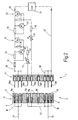
- Fig. 1 shows a schematic diagram of an explosion-proof Connector arrangement 1.
- To the connector arrangement 1 includes two connectors 2 and 3 and a switch device 4, which is a control device 5 is assigned.
- the connector 2 consists of a cuboid Holder or base body 6, which is made of an insulating material is.
- the base body 6 is from a flat front 7, a flat back 8 and side surfaces 9 limited.
- Each bushing seat 11 consists of one at the front 7 adjacent section 13 and a section 14 together.
- the section 13 opens out at the front 7 an insertion opening 15, while the section 14 at one Opening 15 to the back 8 is open.
- the section 14 has a smaller cross section than the section 13, so that the two sections 13 and 14 on a shoulder 16 merge.
- the shoulders 16 of the socket seats 11d, 11e and 11f is towards the rear 8 offset compared to the shoulders 16 of the socket seats 11a, 11b, 11c and 11g, 11h and 11i. Sit this way the sockets 12 located therein somewhat deeper to the front 7 when the sockets in the Bush seats 11a ... 11c and 11g ... 11i.
- Each socket 12 consists of a metallic tubular section 17 which at its rear into a Solder tail passes through section 14 of the concerned Socket seat 11 from the rear 8 of the carrier 6 protrudes.
- the connector part 3 also consists of a cuboid base body 21 with a front side 22, a rear side 23 and side surfaces 24.
- the base body 21 In the base body 21 are seats aligned with the socket seats 11a ... 11i 24a ... 24i included.
- the seats 24a ... 24i have a similar one Shape like the socket seats 11 and extend from the front 22 to the back 23. Since they have a similar shape will have another detailed explanation waived.
- the connector pins 26c ... 26e measured from the Front 22, a slightly shorter length than the connector pins 26a ... 26c or 26g ... 26i.
- the Insert the plug pins 26 into the associated sockets 12 first the connector pins 26a ... 26c and the Connector pins 26g ... 26i with the associated sockets 12 make an electrical contact before making an electrical conductive connection between the connector pins 26c ... 26f with the associated sockets 12 in the socket seats 11d ... 11f comes about, i.e. contacting the connector pins 26d ... 26f lags behind when plugged together.
- This Measure alone would suffice.
- a lowering the sockets 12 in the socket seats 11d..11f is not absolutely necessary.
- the switch device 4 is on with its input 30 the three electrically connected in parallel to each other Connector pins 26a ... 26c connected. It contains the input side a fuse 31 with which a current sensor resistor 32 is in series. To the current sensor resistor 32, as shown, closes a PNP transistor 33 whose emitter is connected to resistor 32 while its collector is connected to another current sensor resistor 34 is switched on. With this in turn lies second PNP transistor 35 in series, with its emitter is connected to the current sensor resistor 34. The collector of the transistor 35 leads via a connecting line 36 to a load or a consumer 37.
- The is parallel to the current sensor resistor 32 Base-emitter path of a PNP transistor 38, specifically in such a way that its emitter at the junction between the Fuse 31 and the current sensor resistor 32 connected while the base is connected to the emitter of transistor 33 connected is.
- the collector of transistor 38 is present the base of transistor 33 and also to the base-emitter path of the transistor 33, a bleeder resistor 39 connected in parallel.
- Another similar configuration is to the transistor 35 connected, and is parallel to that Current sensor resistor 34 the base-emitter path of a PNP transistor 41, whose emitter with the collector of Transistor 33 is connected while its base is connected to the Emitter of transistor 35 is turned on.
- the collector of transistor 41 leads to the base of transistor 35, its base emitter path also over another Discharge resistor 42 is shunted.
- a resistor 43 leads to it series-connected PTC resistor 44, the thermally with the housing of transistor 33 is coupled.
- the other The end of the PTC resistor 44 is connected to the plug pin 26d electrically connected.
- the plug pin 26e is connected to a PTC resistor 45 connected from where the electrical connection via a Resistor 46 continues to the collector of transistor 41 or the base of transistor 35 leads.
- the PTC resistor 35 is thermally fixed to the housing of transistor 35 coupled.
- the connector pins 26f ... 26i are on their solder lugs 28 connected to each other and are connected to a circuit ground 47, on which the load 37 is also switched on with its cold end is.
- the sockets in the socket seats 11d ... 11f 12 are short-circuited to one another via a line 49, however, from all other sockets 12 galvanically Cut. After all, they are also in the socket seats 11g ... 11i existing sockets 12 together galvanically connected and for example via a line 51 with the negative pole of the aforementioned power source shown connected, the negative pole, for example, the switching ground represents.
- the contact pins 26a ... 26c with the associated sockets 12 in the connector 2 and at the same time the contact pins 26g ... 26i with the corresponding sockets 12 a galvanic connection produce. This creates a galvanic connection between the live line 48 and the Input 30 of the switch device 4, formed by the Fuse 31 and between the line 51 and the Line 47.
- the contact pins 26d ... 26f are initially by the associated sockets 12 can still be separated. This means, that neither transistor 33 nor transistor 35 is on its base gets a corresponding negative bias. Rather, the respective basis is about the shunt resistance 39 or 42 connected to the associated emitter, so that both transistors 33 and 35 are blocked.
- the Output line 36 will consequently be de-energized and it can no current flow through consumer 37; the connection about the consumer 37 i.e. the main circuit is broken.
- a base current for the Transistor 35 by one from the base of transistor 35 via the resistor 46, the PTC resistor 45, the connector pin 26e, the line 49 to the connector pin 26f and in turn flows to the circuit ground 47.
- the main circuit is now released.
- the Consumer or the load 37 can now take electricity.
- transistor 33 or transistor 35 is switched off or both transistors are used at the same time switched off when first the plug pin 26f from the associated socket 12 is released. This will cause the Output 36 the voltage for consumer 37 is switched off, i.e. it becomes the connector between the two Connectors 2 and 3 de-energized, although still one galvanic connection for the main circuit exists.
- Fig. 2 shows a circuit arrangement which is different from differs from the embodiment of FIG. 1 in that that the contact sockets 12, which with the connector pins 26d and 26e cooperate, via a line 52 directly with the Lead 51 are connected.
- the connector pin 26f can be saved, although it is still illustrated in FIG. 2 is.
- the switch device 4 differs from the previous two essentially by location the switch device 4. It is on the side the power supply between the power supply and the Connector while connector 3 is galvanic is connected directly to the consumer 37. As a result, the emitter of the transistor 35 is connected to the sockets 12 for the connector pins 26a ... 26c.
- the two PTC resistors 44 and 45 are corresponding with the sockets 12 for the Connector pins 26d and 26e connected while on the side of the connector 3, the connector pins 26d ... 26f via a Line 52 directly with line 47 and thus the connector pins 26g ... 26i are connected.
- a protective collar 55 is integrally formed on the base body 21, which has a greater axial extent than the connector pins 26. When inserted, it overlaps the Base body 6 of the connector 2. So that the Inserting bare sections into the connector the connector pins 26 protected.
- a connector arrangement has two connector strips on, in the mated condition of the Electricity flows from a power source to a consumer. Between a connector strip and the power source or the consumer sits a switch device whose Control signal also via the two connector strips leads. The contacts for the main circuits hurry while the contacts for the control current lag so that the main circuits are already closed before the Control circuit is turned on. This will create a Current flow in the main circuits when plugging or unplugging of main circuit contacts prevented.
Description
Aus der EP 0 261 307 ist ein explosionsgeschütztes Modulgehäuse bekannt, das in explosionsgefährdeten Bereichen angeordnet werden kann und dazu vorgesehen ist, mit weiteren gleichen Modulgehäusen zusammen in ein Gestell eingesetzt zu werden. Zur elektrischen Verbindung der Modulgehäuse untereinander bzw. mit einer oder mehreren Stromversorgungen sind an jedem Modulgehäuse zwei Arten von Steckverbindergruppen vorgesehen.EP 0 261 307 describes an explosion-proof device Module housing known, that in hazardous areas can be arranged and is provided with other identical module housings together in one frame to be used. For the electrical connection of the Module housing with one another or with one or more Power supplies are two types of on each module housing Connector groups provided.
Die eine Gruppe wird von Steckerstiften einer handelsüblichen Steckerleiste gebildet, die mit einer ebenfalls handelsüblichen Buchsenleiste im Gestell elektrisch und mechanisch zusammenwirken. Über diese Kontaktstellen werden sämtliche eigensichere Stromkreise geführt.One group is made of pins of a commercially available Power strip formed with a likewise commercially available socket strip in the frame electrical and interact mechanically. Be through these contact points all intrinsically safe circuits.
Eigensichere Stromkreise im Sinne des Explosionsschutzes sind Stromkreise, bei denen die Spannung gegenüber einem anderen stromführenden Leiter unterhalb eines vorbestimmten Spannungsgrenzwertes liegt, der von den zu erwartenden zündfähigen Gasgemischen abhängig ist. Außerdem muss zwangsläufig sichergestellt sein, dass auf eigensicheren Stromkreisen der Strom unter einer vorbestimmten Grenze bleibt, die ebenfalls von der Zündfähigkeit des zu erwartenden Gemisches abhängig ist.Intrinsically safe circuits in terms of explosion protection are circuits in which the voltage against one other current-carrying conductor below a predetermined one Voltage limit is that of the expected ignitable gas mixtures is dependent. In addition, must inevitably ensure that on intrinsically safe Circuits the current below a predetermined limit remains, which also depends on the ignitability of the expected Mixture is dependent.
Da diese Bedingung nicht notwendigerweise auch für die Stromversorgung gilt, denn hier ist die Spannung und/oder der maximal zulässige Strom, häufig größer als die Grenzwerte für die Zündschutzart "Eigensicherheit", werden diese nichteigensicheren Stromkreise über Sondersteckverbinder geleitet, die zu der anderen Gruppe gehören.Since this condition is not necessarily for the Power supply applies, because here is the voltage and / or the maximum permissible current, often greater than the limit values for the type of protection "intrinsic safety", these are non-intrinsically safe circuits via special connectors who belong to the other group.
Die Sondersteckverbinder bestehen wiederum aus einer Steckerleiste an dem Modulgehäuse und einer Buchsenleiste im Gestell. Sie sind jedoch so gestaltet, dass der Steckerstift in der Buchsenleiste von einem Kontaktraum umschlossen ist, der bei eingeführtem Stecker die Bedingungen für die Zündschutzart "Druckfeste Kapselung" erfüllt. Hierzu muss der Spalt zwischen der Bohrung in dem Isolierkörper für die Buchse und einer isolierenden Ummantelung des Steckerstiftes die Bedingungen des "Ex-Spaltes" erfüllen. Da diese Toleranzen relativ eng sind, ergibt sich für die Steckverbindermittel der nichteigensicheren Stromkreise ein erheblicher Fertigungs- und Bauaufwand und ein nicht unbeachtlicher Platzbedarf.The special connectors in turn consist of a Plug strip on the module housing and a socket strip in the frame. However, they are designed so that the connector pin enclosed in the socket strip by a contact space is the conditions for when the plug is inserted fulfills the type of protection "flameproof enclosure". For this the gap between the hole in the insulating body for the socket and an insulating jacket of the Plug pin meet the conditions of the "Ex gap". Since these tolerances are relatively narrow, the result for Connector means of the non-intrinsically safe circuits considerable manufacturing and construction costs and a not inconsiderable Space requirements.
Darüber hinaus wird ein zusätzlicher Schalter auf der Gestellseite benötigt, um die Buchsen spannungslos zu schalten, wenn die Steckerstifte aus den Buchsen herausgezogen sind. In addition, an additional switch on the Frame side needed to de-energize the sockets switch when the connector pins are pulled out of the sockets are.
Bei einer anderen aus der EP 0 261 307 bekannten Lösung ist die Buchse für einen nichteigensicheren Stromkreis in dem Buchsenträger beweglich gelagert und bildet zusammen mit einem dahinter befindlichen Kontakt einen Schalter, der beim Einstecken bzw. Herausziehen des Steckerstiftes betätigt wird.In another solution known from EP 0 261 307 is the socket for a non-intrinsically safe circuit movably supported in the socket carrier and forms together with a contact behind it a switch that actuated when inserting or removing the plug pin becomes.
Auch diese Lösung ist mechanisch sehr aufwendig und lässt sich nicht beliebig weit miniaturisieren.This solution is also mechanically very complex and cannot be miniaturized to any extent.
Insbesondere eignen sich beide Lösungen nur für Modulgehäuse ab ca. einer Größe, die zur Aufnahme von Leiterplatten im Europa-Format geeignet sind. Sie eignen sich weniger für miniaturisierte Busschienensysteme, einfach aufgrund ihres Platzbedarfes. Darüber hinaus ist die Lösung wegen der nicht handelsüblichen Stecker- und Buchsenleisten verhältnismäßig teuer.In particular, both solutions are only suitable for module housings From approx. one size, which can be used to hold circuit boards in Europe format are suitable. They are suitable less for miniaturized busbar systems, simple because of their space requirements. Beyond that is the solution because of the non-standard male and female connectors relatively expensive.
Die DE-A-34 46 396 beschreibt ein explosionsgeschütztes elektrisches Verbindersystem, bei dem die Verbraucherseite mit Steckerstiften und die speisende Seite mit Steckbuchsen versehen ist. Über diese Buchsen und Stecker fließt bei zusammengesteckten Verbindungssystemen der Laststrom. Zusätzlich zu diesen Steckern und Buchsen für den Laststrom sind auf der Verbraucherseite zwei weitere Steckerstifte vorhanden, die galvanisch mit einander verbunden und etwas kürzer ausgebildet sind, als die Steckerstifte für den Laststrom. Diese verkürzten Steckerstifte wirken mit entsprechenden Steckbuchsen des Gegenstücks zusammen, die in dem Steuerstromkreis eines Relais oder Schützen liegen. Über die Schaltkontakte des Relais fließt der Laststrom zu den Laststrombuchsen. DE-A-34 46 396 describes an explosion-proof electrical connector system in which the consumer side with plug pins and the feeding side with sockets is provided. It flows through these sockets and plugs in the case of interconnected connection systems, the load current. In addition to these plugs and sockets for the load current are two more connector pins on the consumer side present that are galvanically connected to each other and something are shorter than the connector pins for the Load current. These shortened connector pins work with the corresponding ones Mating sockets of the counterpart, which in the control circuit of a relay or contactor. The load current flows in via the switching contacts of the relay the load current sockets.
Wenn der Stecker eingesteckt ist, wird der Schütz eingeschaltet und es kann der Laststrom über die Hauptstromsteckerstifte fließen. Beim Herausziehen der Steckereinheit wird zunächst der Steuerstromstromkreis getrennt, wodurch die Hauptstromsteckerstifte spannungslos werden, damit sie sich schließlich ohne die Gefahr eines Öffnungsfunkens aus den Buchsen herausziehen lassen.When the plug is inserted, the contactor is switched on and it can load current through the main power connector pins flow. When pulling out the plug unit the control circuit is first disconnected, whereby the main power connector pins become dead so they finally get along without the danger of an opening spark let the bushes pull out.
Eine ähnliche Anordnung ist in der DE-A-32 12 983 gezeigt, bei der jedoch als schaltendes Element ein Halbleiterschalter vorhanden ist.A similar arrangement is shown in DE-A-32 12 983, in which, however, as a switching element, a semiconductor switch is available.
Ausgehend hiervon ist es Aufgabe der Erfindung eine Steckverbindungsanordnung zu schaffen, die einen geringen mechanischen Aufwand erfordert, kostengünstiger und/oder raumsparender ist und für sich genommen die Vorschriften des Explosionsschutzes erfüllt.Based on this, it is an object of the invention To create connector assembly that is low requires mechanical effort, cheaper and / or is space-saving and the regulations in themselves explosion protection.
Diese Aufgabe wird erfindungsgemäß durch die Steckverbindungsanordnung
mit den Merkmalen des Anspruches 1
gelöst.This object is achieved by the connector arrangement
with the features of
Bei der neuen Lösung können auf der Stromversorgungsund auf der Verbraucherseite einfache Steckverbinder verwendet werden. Soweit die Stromkreise, die über diese Steckverbinder geführt werden, nicht eigensicher sind, ist eine steuerbare Schaltereinrichtung hierzu vorgesehen, die einen Eingang und einen Ausgang aufweist. Diese Schaltereinrichtung ist eingangsseitig an den wenigstens einen Steckerstift oder ausgangsseitig an die wenigstens eine Steckbuchse elektrisch angeschlossen. Die Schaltereinrichtung kennt zwei Betriebszustände, nämlich einen niederohmigen Betriebszustand und einen hochohmigen Betriebszustand, jeweils gemessen zwischen Eingang und Ausgang.With the new solution, the power supply and simple connectors are used on the consumer side become. As far as the circuits that go over this Connectors are performed, are not intrinsically safe a controllable switch device is provided for this purpose has an input and an output. This switch device is on the input side to the at least one connector pin or on the output side to the at least one socket electrically connected. The switch device knows two operating states, namely a low impedance Operating state and a high-resistance operating state, each measured between entrance and exit.
Der Schaltereinrichtung ist eine Steuereinrichtung zugeordnet, die mit einem Steuersignal arbeitet, das von dem jeweils anderen Steckverbindungsteil kommt, und zwar in der Weise, dass die Steuereinrichtung die Schalteinrichtung erst dann in den niederohmigen Zustand bringt, wenn der wenigstens eine Steckerstift mit der wenigstens einen Steckbuchse eine zuverlässige elektrisch leitende Verbindung bildet, während umgekehrt die Schalteinrichtung bereits dann in den hochohmigen Zustand gebracht wird, noch bevor beim Trennen die elektrisch leitende Verbindung zwischen dem Steckerstift und der Steckbuchse aufgetrennt wird.The switch device is a control device assigned, which works with a control signal that from the other connector part comes in the way that the control device the switching device brings it into the low-resistance state only when the at least one connector pin with the at least one Socket a reliable electrically conductive connection forms, while conversely the switching device already then brought into the high impedance state, still before disconnecting the electrically conductive connection between the plug pin and the socket becomes.
Zufolge dieser Lösung können an der Trennstelle zwischen Steckbuchse und Steckerstift auf keinen Fall irgendwelche zündfähigen Funken entstehen, da sie immer im stromlosen Zustand miteinander in Verbindung gebracht oder voneinander getrennt werden. Es genügt, wenn die Steckverbindung im gesteckten Zustand zwischen Steckerstift und Steckerbuchse die Anforderungen an die Zündschutzart "Erhöhte Sicherheit" erfüllt oder eine nicht störanfällige Verbindung gemäß den Anforderungen der Zündschutzart "Eigensicherheit" darstellt.As a result of this solution, the separation point between Plug socket and plug pin under no circumstances any ignitable sparks arise because they are always in the de-energized state State associated with each other or from each other be separated. It is sufficient if the plug connection when plugged in between plug and socket the requirements for the type of protection "increased Security "or a connection that is not susceptible to interference according to the requirements of the type of protection "intrinsic safety" represents.
Diese Anforderung können sowohl durch Steckbuchsen oder Stecker mit Vielfachkontaktstellen erzeugt werden, als auch durch einfache Steckbuchsen und Steckerstifte, wenn hiervon mehrere elektrisch parallelgeschaltet sind. Die Sicherheitsvorschriften gehen davon aus, dass in keinem der Fälle sämtliche Kontaktstellen aufgrund von Erschütterungen gleichzeitig Unterbrechungen erleiden, die zu Funken führen könnten.This requirement can be met both through sockets or plugs with multiple contact points are generated as also through simple sockets and pins, if several of them are electrically connected in parallel. The Safety regulations assume that none of the Cases all contact points due to vibrations at the same time suffer interruptions that lead to sparks could.
Bei Verwendung in Busschienensystemen ist es von Vorteil, wenn die Schaltereinrichtung nicht in der Busschiene, sondern auf der Seite des Verbrauchers angeordnet ist.When used in busbar systems, it is advantageous to if the switch device is not in the busbar, but is arranged on the side of the consumer.
Die Unterbringung auf der Seite des Verbrauchers schaltet außerdem automatisch die Steckerstifte spannungslos, was dann erforderlich ist, wenn auf der Verbraucherseite Kondensatoren enthalten sind, die unter Umständen über längere Zeit an den Steckerstiften zu erhöhten Spannungen gegenüber anderen Steckerstiften führen. In diesem Falle würden ohne die Schaltereinrichtung durch das Ablegen auf einer elektrisch leitenden Unterlage Entladungsfunken erzeugt werden können.Housing on the side of the consumer also automatically disconnects the connector pins, which is required if on the consumer side Capacitors are included, which may to increase at the connector pins for a long time Lead voltages against other connector pins. In this Trap would be without the switch device by the Placing discharge sparks on an electrically conductive surface can be generated.
Um Berührungssicherheit zu gewährleisten, sind die Steckerstifte einzeln oder insgesamt von einem Schutzkragen umgeben. Beim Einführen der Steckerstifte in die Steckbuchsen entsteht eine Situation, in der die einzelnen Steckerstifte bereits Spannung führen, ehe sie vollständig in die Steckbuchsen eingesteckt sind. Um in diesem Zustand die an sich freiliegenden Steckerstifte gegen Berührung zu schützen, sind ein oder mehrere Schutzkragen vorgesehen.To ensure safety of touch, they are Plug pins individually or as a whole from a protective collar surround. When inserting the plug pins into the sockets a situation arises in which the individual connector pins already lead to tension before they are completely in the Sockets are inserted. To the in this state protect exposed connector pins against touch, one or more protective collars are provided.
Gleichzeitig können der oder die Schutzkrägen als mechanischer Schutz für die unter Umständen recht filigranen Steckerstifte dienen, wenn der Kragen eine Tiefe aufweist, die größer ist als es der Länge des oder der Steckerstifte entspricht.At the same time, the protective collar or collars as mechanical Protection for those who can be quite delicate Plug pins serve when the collar has a depth which is greater than the length of the connector pin or pins equivalent.
Die Herstellung ist sehr einfach, wenn der Kragen an dem Halterteil aus Isolierstoff einstückig angeformt ist. Manufacturing is very easy when the collar is on the holder part is molded in one piece from insulating material.
Der Raumbedarf für die Schaltereinrichtung wird extrem klein, wenn sie als rein elektronische Schalteinrichtung ausgeführt ist. Sie ist zweckmäßigerweise redundant ausgeführt, damit beim Ausfall eines der wichtigen Halbleiter mit Sicherheit der Stromkreis richtig unterbrochen wird.The space requirement for the switch device becomes extreme small when used as a purely electronic switching device is executed. It is expediently designed to be redundant, if one of the important semiconductors fails the circuit is definitely interrupted correctly.
Das Steuersignal kann in dem Steuerstrom für die Schaltereinrichtung bestehen. Es kommt dann aus dem Steckverbindungsteil, das nicht der Schaltereinrichtung zugeordnet ist, wenn der Steuerstrom wenigstens einmal über die Verbindung zwischen den beiden Steckverbindungsteilen fließt.The control signal can be in the control current for the Switch device exist. It then comes from the connector part, that is not assigned to the switch device is when the control current at least once over the Connection between the two connector parts flows.
Eine besonders zuverlässige und sichere Anordnung wird erreicht, wenn der Steuerstrom zweimal über die beiden Steckverbindungsteile fließt, in der Weise, dass der Strom beispielweise aus der Schaltung des Verbrauchers direkt erhalten wird, wenn die Stromverbindungsanschlüsse für den Verbraucher elektrisch leitend verbunden sind. Der Steuerstromkreis ist in jedem Falle ein eigensicherer Kreis, der keine besonderen Schutzmaßnahmen erfordert.A particularly reliable and safe arrangement will reached when the control current passes through the two twice Plug connector parts flow in such a way that the current for example directly from the circuit of the consumer is obtained when the power connection connections for the Consumers are electrically connected. The control circuit is in any case an intrinsically safe circle that no special protective measures required.
Die gewünschte zeitliche Relation hinsichtlich der Kontaktgabe lässt sich in einfacher Weise durch die räumliche Anordnung der Steckbuchsen bzw. die Länge der Steckerstifte steuern. Durch verkürzte Steckerstifte für den Steuerstromkreis wird das gewünschte Nacheilen beim Zusammenstecken bzw. das erforderliche Vorauseilen beim Trennen erreicht.The desired temporal relation regarding the Contacting can be done easily through the spatial Arrangement of the sockets or the length of the connector pins Taxes. By shortened connector pins for the Control circuit will be the desired lag when plugging together or the necessary advance when separating reached.
Um die Schaltereinrichtungen zu schützen, ist eine Überlastungsschutzeinrichtung vorgesehen. Es können zusätzliche thermische Sensoren vorhanden sein, die zu einem Abschalten führen, sollte die Schaltereinrichtung unzulässige Temperaturen erreichen. Es ist ebenfalls denkbar, den Strom zu erfassen und die Schaltereinrichtungen zwangsweise in den AUS-Zustand zu bringen, sollte der Strom einen vorbestimmten Grenzwert übersteigen, der deutlich niedriger liegt als der zulässige Grenzwert der Bauelemente.An overload protection device is provided to protect the switch devices. There may be additional ones thermal sensors are present that lead to a Switch off, the switch device should not be permitted Reach temperatures. It is also conceivable that Detect current and the switch devices forced in the OFF state, the current should be a predetermined Exceed limit, which is significantly lower is the permissible limit value of the components.
Im Übrigen sind Weiterbildungen der Erfindung Gegenstand von Unteransprüchen.In addition, developments of the invention are the subject of subclaims.
In der Zeichnung sind Ausführungsbeispiele des Gegenstandes
der Erfindung dargestellt. Es zeigen:
Fig. 1 zeigt eine Prinzipdarstellung einer explosionsgeschützten
Steckverbindungsanordnung 1. Zu der Steckverbindungsanordnung
1 gehören zwei Steckverbinder 2 und 3
sowie eine Schaltereinrichtung 4, der eine Steuereinrichtung
5 zugeordnet ist.Fig. 1 shows a schematic diagram of an explosion-
Der Steckverbinder 2 besteht aus einem quaderförmigen
Halter oder Grundkörper 6, der aus einem Isolierstoff hergestellt
ist. Der Grundkörper 6 wird von einer ebenen Vorderseite
7, einer ebenen Rückseite 8 und Seitenflächen 9
begrenzt.The
Beim gezeigten Ausführungsbeispiel sind in dem Grundkörper
6 insgesamt neun Durchgangsöffnungen 11a...11i vorhanden,
die von der Vorderseite 7 bis zu der Rückseite 8
reichen. Sie dienen als Sitz für darin befindliche Steckbuchsen
12.In the embodiment shown are in the base body
6 a total of nine through
Jeder Buchsensitz 11 setzt sich aus einem an die Vorderseite
7 angrenzenden Abschnitt 13 und einem Abschnitt 14
zusammen. Der Abschnitt 13 mündet an der Vorderseite 7 mit
einer Einstecköffnung 15, während der Abschnitt 14 an einer
Öffnung 15 zu der Rückseite 8 hin offen ist. Der Abschnitt
14 hat einen kleineren Querschnitt als der Abschnitt 13, so
dass die beiden Abschnitte 13 und 14 an einer Schulter 16
ineinander übergehen. Die Schultern 16 der Buchsensitze
11d, 11e und 11f ist in Richtung auf die Rückseite 8 hin
versetzt, verglichen mit den Schultern 16 der Buchsensitze
11a, 11b, 11c und 11g, 11h und 11i. Auf diese Weise sitzen
die darin befindlichen Steckbuchsen 12 etwas tiefer, bezogen
auf die Vorderseite 7, als die Steckbuchsen in den
Buchsensitzen 11a...11c sowie 11g...11i. Each
Jede Steckbuchse 12 besteht aus einem metallischen
rohrförmigen Abschnitt 17, der an seiner Rückseite in eine
Lötfahne übergeht, die durch den Abschnitt 14 des betreffenden
Buchsensitzes 11 aus der Rückseite 8 des Trägers 6
heraussteht.Each
Der Steckverbinderteil 3 besteht ebenfalls aus einem
quaderförmigen Grundkörper 21 mit einer Vorderseite 22,
einer Rückseite 23 sowie Seitenflächen 24. In dem Grundkörper
21 sind mit den Buchsensitzen 11a...11i fluchtende Sitze
24a...24i enthalten. Die Sitze 24a...24i haben eine ähnliche
Form wie die Buchsensitze 11 und reichen von der Vorderseite
22 bis zur Rückseite 23. Da sie eine ähnliche Gestalt
haben, wird auf eine erneute ausführliche Erläuterung
verzichtet.The connector part 3 also consists of a
In den Sitzen 24a...24i sind metallische Stecker-stifte
26 verankert, die aus der Vorderseite 22 parallel zueinander
vorstehen. An der Rückseite gehen die Steckerstifte
jeweils in verdickte Grundkörper 27 über, die schließlich
in einer Lötfahne 28 enden, die aus der Rückseite des
Grundkörpers 21 vorsteht.There are metallic connector pins in the seats 24a ... 24i
26 anchored from the front 22 parallel to each other
protrude. The connector pins go on the back
each in thickened
Die Steckerstifte 26c...26e haben, gemessen ab der
Vorderseite 22, eine etwas geringere Länge als die Steckerstifte
26a...26c bzw. 26g...26i. Dadurch werden beim
Einführen der Steckerstifte 26 in die zugehörigen Steckbuchsen
12 zunächst die Steckerstifte 26a...26c und die
Steckerstifte 26g...26i mit den zugehörigen Steckbuchsen 12
einen elektrischen Kontakt herstellen, ehe eine elektrisch
leitende Verbindung zwischen den Steckerstiften 26c...26f
mit den zugehörigen Steckbuchsen 12 in den Buchsensitzen
11d...11f zustandekommt, d.h. die Kontaktgabe der Steckerstifte
26d...26f eilt beim Zusammenstecken nach. Beim Trennen
werden umgekehrt die Stromkreise über diese Steckerstifte
26d...26f vorauseilen, d.h. als erste getrennt. Diese
Maßnahme alleine würde bereits genügen. Ein Tiefersetzen
der Steckbuchsen 12 in den Buchsensitzen 11d..11f ist nicht
unbedingt zusätzlich erforderlich.The connector pins 26c ... 26e, measured from the
Die Schaltereinrichtung 4 ist mit ihrem Eingang 30 an
die drei elektrisch zueinander parallel geschalteten
Steckerstifte 26a...26c angeschlossen. Sie enthält eingangsseitig
eine Schmelzsicherung 31, mit der ein Stromfühlerwiderstand
32 in Serie liegt. An den Stromfühlerwiderstand
32 schließt sich, wie gezeigt, eine PNP-Transistor 33
an, dessen Emitter mit dem Widerstand 32 verbunden ist,
während sein Kollektor an einen weiteren Stromfühlerwiderstand
34 angeschaltet ist. Mit diesem wiederum liegt ein
zweiter PNP-Transistor 35 in Serie, wobei dessen Emitter
mit dem Stromfühlerwiderstand 34 verbunden ist. Der Kollektor
des Transistors 35 führt über eine Verbindungsleitung
36 zu einer Last oder einem Verbraucher 37.The switch device 4 is on with its
Parallel zu dem Stromfühlerwiderstand 32 liegt die
Basis-Emitterstrecke eines PNP-Transistors 38, und zwar so,
dass dessen Emitter an der Verbindungsstelle zwischen der
Sicherung 31 und dem Stromfühlerwiderstand 32 angeschlossen
ist, während die Basis mit dem Emitter des Transistors 33
verbunden ist. Der Kollektor des Transistors 38 liegt an
der Basis des Transistors 33 und außerdem ist zu der Basis-Emitterstrecke
des Transistors 33 ein Ableitwiderstand 39
parallelgeschaltet.The is parallel to the
Eine weitere ähnliche Konfiguration ist an den Transistor
35 angeschlossen, und zwar liegt parallel zu dem
Stromfühlerwiderstand 34 die Basis-Emitterstrecke eines
PNP-Transistors 41, dessen Emitter mit dem Kollektor des
Transistors 33 verbunden ist, während seine Basis an den
Emitter des Transistors 35 angeschaltet ist. Der Kollektor
des Transistors 41 führt zu der Basis des Transistors 35,
dessen Basisemitterstrecke ebenfalls über einen weiteren
Ableitwiderstand 42 geshuntet ist.Another similar configuration is to the
Von der Basis des Transistors 33 bzw. dem Kollektor
des Transistors 38 führt ein Widerstand 43 zu einem damit
in Serie geschalteten PTC-Widerstand 44, der thermisch mit
dem Gehäuse des Transistors 33 gekoppelt ist. Das andere
Ende des PTC-Widerstandes 44 ist mit dem Steckerstift 26d
elektrisch verbunden.From the base of
Der Steckerstift 26e ist an einen PTC-Widerstand 45
angeschlossen, von wo die elektrische Verbindung über einen
Widerstand 46 weiter zu dem Kollektor des Transistors 41
bzw. der Basis des Transistors 35 führt. Der PTC-Widerstand
35 ist thermisch fest mit dem Gehäuse des Transistors 35
gekoppelt.The
Die Steckerstifte 26f...26i sind an ihren Lötfahnen 28
miteinander verbunden und liegen an einer Schaltungsmasse
47, an der auch die Last 37 mit ihrem kalten Ende angeschaltet
ist.The connector pins 26f ... 26i are on their solder lugs 28
connected to each other and are connected to a
Bei dem Steckverbinderteil 2 sind die in den Buchsensitzen
11a...11c enthaltenen Steckbuchsen 12 miteinander
verbunden und über eine Leitung 48 beispielsweise mit dem
Pluspol einer nicht gezeigten Stromquelle verbunden.In the
Die in den Buchsensitzen 11d...11f sitzenden Steckbuchsen
12 sind über eine Leitung 49 miteinander kurzgeschlossen,
jedoch von allen übrigen Steckbuchsen 12 galvanisch
getrennt. Schließlich sind auch die in den Buchsensitzen
11g...11i vorhandenen Steckbuchsen 12 miteinander
galvansich verbunden und beispielsweise über eine Leitung
51 mit dem Minuspol der vorerwähnten gezeigten Stromquelle
verbunden, wobei der Minuspol beispielsweise die Schaltmasse
darstellt.The sockets in the
Die Funktionsweise der gezeigten Anordnung ist wie folgt:The operation of the arrangement shown is like follows:
Sobald der Steckverbinder 3 in den Steckverbinder 2
eingeführt wird, werden zunächst die Kontaktstifte 26a...
26c mit den zugehörigen Steckbuchsen 12 in dem Steckverbinder
2 und gleichzeitig die Kontaktstiften 26g...26i mit den
korrespondierenden Steckbuchsen 12 eine galvanische Verbindung
herstellen. Damit entsteht eine galvanische Verbindung
zwischen der unter Spannung stehenden Leitung 48 und dem
Eingang 30 der Schaltereinrichtung 4, gebildet durch die
Schmelzsicherung 31 sowie zwischen der Leitung 51 und der
Leitung 47.As soon as the connector 3 in the
Die Kontaktstifte 26d...26f werden anfänglich von den
zugehörigen Steckbuchsen 12 noch getrennt sein. Dies bedeutet,
dass weder der Transistor 33 noch der Transistor 35 an
seiner Basis eine entsprechende negative Vorspannung bekommt.
Vielmehr ist die jeweilige Basis über den Shuntwiderstand
39 bzw. 42 mit dem zugehörigen Emitter verbunden,
so dass beide Transistoren 33 und 35 gesperrt sind. Die
Ausgangsleitung 36 wird folglich stromlos sein und es kann
kein Strom durch den Verbraucher 37 fließen; die Verbindung
über den Verbraucher 37 d.h. der Hauptstromkreis ist unterbrochen. The contact pins 26d ... 26f are initially by the
associated
Die Kontaktgabe zwischen den Kontaktstiften 26a...26c
bzw. den Kontaktstiften 26g...26i mit den zugehörigen
Steckbuchsen 12 wird folglich stromlos sein, womit auf keinen
Fall ein Funke erzeugt werden kann.The contact between the contact pins 26a ... 26c
or the contact pins 26g ... 26i with the associated
Wenn der Steckverbinder 3 tiefer in den Steckverbinder
2 eingesteckt wird, gleiten ohne Stromunterbrechung die
Kontaktstifte 26a...26c sowie 26g...26i zunehmend tiefer in
die zugehörigen Steckbuchsen 12 ein. Ab einer bestimmten
Einstecktiefe werden sodann auch die Steckerstifte 26d...
26f mit den zugehörigen Steckbuchsen in Berührung kommen
und eine entsprechende galvanische Verbindung herstellen.
Nachdem diese galvanische Verbindung hergestellt ist, entsteht
ein Stromkreis von der Basis des Transistors 33 über
den Widerstand 43, den PTC-Widerstand 44, den Steckerstift
26d zu der zugehörigen Steckbuchse 12, von dort über die
Leitung 49 zu der Steckbuchse für den Steckerstift 26f und
von hier zur Schaltungsmasse 47. Der fließende Steuerstrom
steuert den Transistor 33 auf.If the connector 3 goes deeper into the
In ähnlicher Weise entsteht ein Basisstrom für den
Transistor 35, indem ein aus der Basis des Transistors 35
über den Widerstand 46, den PTC-Widerstand 45, den Steckerstift
26e, die Leitung 49 zu dem Steckerstift 26f und
wiederum zur Schaltungsmasse 47 fließt. Dadurch sind nunmehr
beide Transistoren 33 und 35 niederohmig und der Ausgang
36 ist niederohmig mit den Steckerstiften 26a...26c
verbunden. Der Hauptstromkreis ist damit freigegeben. Der
Verbraucher bzw. die Last 37 kann nun Strom entnehmen.A base current for the
Wenn im vollen Betrieb nun der Steckverbinder 3 von
dem Steckverbinder 2 getrennt werden soll, beispielsweise
weil das mit dem Steckverbinder 3 mechanisch gekoppelte
Gerät, symbolisiert durch den Verbraucher 37, entfernt oder
durch ein anderes Gerät ersetzt werden soll, braucht die
Spannung auf den Leitungen 48 und 51 nicht zuvor abgeschaltet
zu werden. Beim Herausziehen des Steckverbinders 3 wird
als erstes die galvanische Verbindung an einem der Steckerstifte
26d...26f unterbrochen, während die Steckerstifte
26a...26c bzw. 26g...26i immer noch in den zugehörigen
Steckbuchsen 12 stecken und die elektrische Verbindung
herstellen.If the connector 3 from
the
Sobald einer der Steckerstifte 26d...26f die galvanische
Verbindung mit der zugehörigen Steckbuchse 12 verliert,
wird der Transistor 33 oder der Transistor 35 abgeschaltet
oder es werden beide Transistoren gleichzeitig
abgeschaltet, wenn als erstes der Steckerstift 26f aus der
zugehörigen Steckbuchse 12 freikommt. Dadurch wird an dem
Ausgang 36 die Spannung für den Verbraucher 37 abgeschaltet,
d.h. es wird die Steckverbindung zwischen den beiden
Steckverbindern 2 und 3 stromlos, obwohl nach wie vor eine
galvanische Verbindung für den Hauptstromkreis besteht. Das
anschließende mechanische Trennen der Steckerstifte 26a...
26c von den zugehörigen Steckbuchsen 12 bzw. der Steckerstifte
26g...26i von deren zugehörigen Steckbuchsen 12 kann,
weil kein Strom mehr fließt, keinen elektrischen Funken
mehr erzeugen.As soon as one of the connector pins 26d ... 26f the galvanic
Loses connection with the associated
Der Strom, der über die Steckerstifte 26d...26f beim Trennen fließt, ist so klein, dass ein Funken nicht hervorgerufen werden kann. Es genügt also, wenn die galvanischen Verbindungen an den Steckerstiften 26a...26c bzw. 26g...26i die Schutzvoraussetzungen der Schutzart "Erhöhte Sicherheit" oder "Eigensicherheit" erfüllen. "Druckfeste Kapselung" ist nicht notwendig.The current that the connector pins 26d ... 26f at Separation flows is so small that a spark is not produced can be. It is therefore sufficient if the galvanic Connections at the connector pins 26a ... 26c or 26g ... 26i the protection requirements of protection type "increased security" or "intrinsic safety". "Pressure proof encapsulation" is not necessary.
Bei herausgezogenem Gerät sind die Transistoren 33 und
35 gesperrt. Ein in dem Verbraucher 37 vorhandener Kondensator
kann keine Spannung an den Steckerstiften 26a...26c
gegenüber den Steckerstiften 26g...26i hervorrufen.When the device is pulled out, the
Da die Basisvorspannung von der Masseleitung 47 auf
der Seite des Steckverbinders 3 abgenommen wird, kann der
Basisstrom auch nur dann fließen, wenn die Steckerstifte
26i...26g eine hinreichende galvanische Verbindung mit der
Zuleitung 51 haben.Because the base bias from the
Im Normalbetrieb, d.h. unterhalb der zulässigen Stromgrenze,
ist der Spannungsabfall an dem Stromfühlerwiderstand
32 kleiner als die Spannung, die erforderlich ist, um
den Transistor 38 aufzusteuern, so dass der Transistor 33
durchgesteuert werden kann. Gleiches gilt für den Spannungsabfall
an dem Widerstand 34, der ebenfalls kleiner ist
als die Basis-Emitterspannung, die erforderlich ist, um den
Transistor 41 durchzusteuern. Wenn der Strom jedoch eine
vorher festgelegte Grenze übersteigt, wird an einem der
beiden Transistoren 41 oder 38 der Spannungsabfall am zugehörigen
Widerstand 34 bzw. 32 über den entsprechenden
Grenzwert steigen und den zugehörigen Transistor 41 oder 38
aufsteuern. Der Transistor 38 oder 41, je nachdem, welcher
früher aufsteuert, erzeugt einen Kurzschluss für die Basis-Emitterstrecke
des Transistors 33 oder des Transistors 35,
wodurch dieser in den Sperrzustand übergeht. Die
Schaltereinrichtung 4 geht in den hochohmigen oder AUS-Zustand
über und schaltet den Strom für die Last 37 ab. In normal operation, i.e. below the permissible current limit,
is the voltage drop across the
Mit Hilfe der beiden PTC-Widerstände 44 und 45 wird
die Temperatur des Transistors 33 sowie des Transistors 35
überwacht. Sollte z.B. die Temperatur des Transistors 33
auf einen zu hohen Wert ansteigen, wird der PTC-Widerstand
44, der mit diesem Transistor thermisch sehr eng gekoppelt
ist, hochohmig, wodurch der Basisstrom gesperrt und der
Transistor 33 abgeschaltet wird. In ähnlicher Weise arbeiten
der Transistor 35 und der PTC-Widerstand 45 zusammen.With the help of the two
Die Bedingung "Erhöhte Sicherheit" oder "nicht störanfällige Verbindung" gemäß der Zündschutzart "Eigensicherheit" wird durch das Parallelschalten mehrerer Steckerstifte 26a...26c bzw. 26g...26i erreicht, denn es wird angenommen, dass bei einer Bewegung der Steckerstifte in den Steckbuchsen nicht an allen Kontaktstellen gleichzeitig Mikrounterbrechungen auftreten können, die zu Funken führen.The condition "increased security" or "not prone to failure Connection "according to the type of protection" intrinsic safety " is achieved by connecting several connector pins in parallel 26a ... 26c or 26g ... 26i reached, because it is assumed that when the connector pins move into the Sockets not at all contact points at the same time Micro-interruptions can occur that lead to sparks.
Eine andere Möglichkeit, die Bedingung "Erhöhte Sicherheit"
oder "nicht störanfällige Verbindung" gemäß der
Zündschutzart "Eigensicherheit" zu erreichen, besteht darin,
beispielsweise die Steckbuchsen 12 als Multilamellenbuchsen
auszubilden, die eine Vielzahl von gleichzeitigen
Kontaktstellen bereitstellen.Another way to improve the security condition
or "connection not susceptible to interference" according to the
To achieve type of protection "intrinsic safety" consists in
for example the
Fig. 2 zeigt eine Schaltungsanordnung, die sich von
dem Ausführungsbeispiel nach Fig. 1 dadurch unterscheidet,
dass die Kontaktbuchsen 12, die mit den Steckerstiften 26d
und 26e zusammenwirken, über eine Leitung 52 direkt mit der
Zuleitung 51 verbunden sind. Es kann der Steckerstift 26f
eingespart werden, obwohl er in Fig. 2 noch veranschaulicht
ist. Fig. 2 shows a circuit arrangement which is different from
differs from the embodiment of FIG. 1 in that
that the
Das Ausführungsbeispiel nach Fig. 3 unterscheidet sich
von den beiden vorherigen im Wesentlichen durch die Lage
der Schaltereinrichtung 4. Sie befindet sich auf der Seite
der Stromversorgung zwischen der Stromversorgung und dem
Steckverbinder, während der Steckverbinder 3 galvanisch
direkt an den Verbraucher 37 angeschlossen ist. Demzufolge
liegt der Emitter des Transistors 35 an den Steckbuchsen 12
für die Steckerstifte 26a...26c. Die beiden PTC-Widerstände
44 und 45 sind entsprechend mit den Steckbuchsen 12 für die
Steckerstifte 26d und 26e verbunden, während auf der Seite
des Steckverbinders 3 die Steckerstifte 26d...26f über eine
Leitung 52 direkt mit der Leitung 47 und damit den Steckerstiften
26g...26i verbunden sind.3 differs
from the previous two essentially by location
the switch device 4. It is on the side
the power supply between the power supply and the
Connector while connector 3 is galvanic
is connected directly to the
Das elektrische Schaltverhalten der Schaltereinrichtung
4 beim Einstecken des Steckverbinders 3 in den Steckverbinder
2 ist sinngemäß das Gleiche, wie dies im Zusammenhang
mit Fig. 1 sehr ausführlich erläutert ist. In jedem
Falle wird die Leitung 36 erst dann stromführend, wenn auch
die galvanische Verbindung mit den Steckerstiften 26d bzw.
26f hergestellt ist, so dass ein Basisstrom aus den Transistoren
33 und 35 zu der Leitung 47 fließen kann, die bereits
vorab mit der Leitung 51 galvanisch verbunden wurde.The electrical switching behavior of the switch device
4 when inserting the connector 3 into the
Um die Steckerstifte 26 mechanisch zu schützen, ist an
dem Grundkörper 21 ein Schutzkragen 55 einstückig angeformt,
der eine größere axiale Erstreckung hat als die Steckerstifte
26. Im eingesteckten Zustand übergreift er den
Grundkörper 6 des Steckverbinders 2. Damit sind die beim
Einführen in den Steckverbinder noch blank liegenden Abschnitte
der Steckerstifte 26 geschützt.To mechanically protect the connector pins 26 is on
a
Eine Steckverbindungsanordnung weist zwei Steckverbinderleisten auf, über die im zusammengesteckten Zustand der Strom von einer Stromquelle zu einem Verbraucher fließt. Zwischen einer Steckverbinderleiste und der Stromquelle bzw. dem Verbraucher sitzt eine Schaltereinrichtung, deren Steuersignal ebenfalls über die beiden Steckverbinderleisten führt. Die Kontakte für die Hauptstromkreise eilen vor, während die Kontakte für den Steuerstrom nacheilen, so dass die Hauptstromkreise bereits geschlossen sind, ehe der Steuerstromkreis eingeschaltet wird. Dadurch wird ein Stromfluss in den Hauptstromkreisen beim Stecken oder Trennen der Kontakte der Hauptstromkreise verhindert.A connector arrangement has two connector strips on, in the mated condition of the Electricity flows from a power source to a consumer. Between a connector strip and the power source or the consumer sits a switch device whose Control signal also via the two connector strips leads. The contacts for the main circuits hurry while the contacts for the control current lag so that the main circuits are already closed before the Control circuit is turned on. This will create a Current flow in the main circuits when plugging or unplugging of main circuit contacts prevented.
Claims (23)
- Explosion-proof plug connector arrangement (1) between a power supply and a load (37),
with a first plug connector part (2), which has at least one socket (12), which is disposed in a holder part (6) made of an insulating material, and the plug-in opening (15) of which is accessible through an associated access opening in the holder part (6),
with a second plug connector part (3), which has at least one plug pin (26), which is disposed in a holder part (21) made of an insulating material,
with at least one controllable switch means (4), which has an inlet (30) and an outlet (36), is electrically connected on the inlet side to the at least one plug pin (26) or on the outlet side to the at least one socket (12), and has two switching statuses, wherein in one switch status the switch means (4) is high-impedance between its inlet (30) and its outlet (36) and in the other switch status the switch means (4) is low-impedance between its inlet (30) and its outlet (36),
with a control means (5) containing a control circuit, the control signal of which comes from the plug connector part (2, 3) which is not directly associated with the switch means (4), wherein configuration of the control means (5) is such:and characterised by an overload protection means (44, 45; 38, 41) which is provided to protect the switch means (4).that it only brings the switch means (4) into the low-impedance status when the at least one plug pin (26) forms an electrically conductive connection with the at least one socket (12), andthat it already brings the switch means (4) into the high-impedance status when it is still forming an electrically conductive connection with the at least one socket (12) on disconnection of the at least one plug pin (26), - Plug connector arrangement according to Claim 1, characterised in that the switch means (4) is provided on the side of the plug connector arrangement (1) which corresponds to the load (37).
- Plug connector arrangement according to Claim 1, characterised in that the first plug connector part (2) and the second plug connector part (3) are coordinated to one another.
- Plug connector arrangement according to Claim 1, characterised in that the at least one socket (12) is disposed in the first plug connector part (2) in a manner protected from contact.
- Plug connector arrangement according to Claim 1, characterised in that the second plug connector part (3) has a collar (55), which surrounds the at least one plug pin (26) or several plug pins (26) jointly.
- Plug connector arrangement according to Claim 5, characterised in that the collar (55) has a depth which is greater than the length of the at least one plug pin (26).
- Plug connector arrangement according to Claim 5, characterised in that the collar (55) is moulded in one piece on the holder part (21) made of insulating material.
- Plug connector arrangement according to Claim 1, characterised in that for each electrical connection between the power supply and the load (37), it has at least one socket (12) and an associated plug pin (26), wherein the combination meets the protection conditions "increased safety" or "non fault-prone connection" in accordance with the protection type "intrinsic safety".
- Plug connector arrangement according to Claim 1, characterised in that for each electrical connection between the power supply and the load (37), it has at several sockets (12) and associated plug pins (26), which are electrically connected in parallel, wherein none of the combinations alone meets the protection conditions "increased safety" or "non fault-prone connection" in accordance with the protection type "intrinsic safety".
- Plug connector arrangement according to Claim 1, characterised in that the switch means (4) is an electronic switch means.
- Plug connector arrangement according to Claim 1, characterised in that the switch means (4) is of redundant configuration.
- Plug connector arrangement according to Claim 1, characterised in that the switch means (4) includes at least one semiconductor (33, 35) with control input as the switch.
- Plug connector arrangement according to Claim 1, characterised in that the switch means (4) includes at least two semiconductors (33, 35) with control input as the switch.
- Plug connector arrangement according to Claim 1, characterised in that a control circuit belonging to the control means (5) is assigned to the respective control input, and that the control circuit (5) is looped over the two plug connector parts (2, 3).
- Plug connector arrangement according to Claim 1, characterised in that the control circuit (5) leads from the second plug connector part (3) to the first plug connector part (2).
- Plug connector arrangement according to Claim 1, characterised in that the control circuit (5) loops back from the first plug connector part (2) to the second plug connector part (3).
- Plug connector arrangement according to Claim 1, characterised in that the control means (5) has at least one control connector socket (12) and at least one control plug pin (26d ..f) for the control circuit (5), and that the control connector socket (12) is contained in the first plug connector part (2) and the control plug pin (26d..f) is contained in the second plug connector part (3).
- Plug connector arrangement according to Claim 17, characterised in that the control plug pin (26d ..f) and the control connector socket (12) are housed in the respective holder part (6, 21) in such a way that they only generate an electrical connection when the electrical connection via the at least one socket (12) and the at least one plug pin (26) already exists.
- Plug connector arrangement according to Claim 1, characterised in that the control circuit (5) contains at least one sensor (44, 45).
- Plug connector arrangement according to Claim 19, characterised in that the sensor (44, 45) is a temperature sensor.
- Plug connector arrangement according to Claim 20, characterised in that the temperature sensor (44, 45) is thermally coupled to the switch means (4).
- Plug connector arrangement according to Claim 1, characterised in that a current sensor (32, 34) is in series with the switch means (4) and a limiter means (38, 41) is assigned to the switch means (4) for locking the switch means (4) when a power limit value is exceeded.
- Plug connector arrangement according to Claim 1, characterised in that the power supply is a part of a bus and the consumer device is a device connected to the bus.
Applications Claiming Priority (3)
| Application Number | Priority Date | Filing Date | Title |
|---|---|---|---|
| DE19838492 | 1998-08-25 | ||
| DE19838492A DE19838492A1 (en) | 1998-08-25 | 1998-08-25 | Explosion-proof connector assembly |
| PCT/DE1999/002603 WO2000011758A1 (en) | 1998-08-25 | 1999-08-19 | Explosion-proof plug-in connector |
Publications (2)
| Publication Number | Publication Date |
|---|---|
| EP1108273A1 EP1108273A1 (en) | 2001-06-20 |
| EP1108273B1 true EP1108273B1 (en) | 2003-02-19 |
Family
ID=7878592
Family Applications (1)
| Application Number | Title | Priority Date | Filing Date |
|---|---|---|---|
| EP99953537A Expired - Lifetime EP1108273B1 (en) | 1998-08-25 | 1999-08-19 | Explosion-proof plug-in connector |
Country Status (3)
| Country | Link |
|---|---|
| EP (1) | EP1108273B1 (en) |
| DE (2) | DE19838492A1 (en) |
| WO (1) | WO2000011758A1 (en) |
Cited By (2)
| Publication number | Priority date | Publication date | Assignee | Title |
|---|---|---|---|---|
| EP2187721A1 (en) | 2008-11-17 | 2010-05-19 | Siemens Aktiengesellschaft | Assembly with a module and a module rack |
| US20110248021A1 (en) * | 2010-04-09 | 2011-10-13 | Whirlpool Corporation | Movable cooking appliance |
Families Citing this family (14)
| Publication number | Priority date | Publication date | Assignee | Title |
|---|---|---|---|---|
| JP2001250646A (en) | 2000-03-02 | 2001-09-14 | Yazaki Corp | Connector and circuit to prevent arc discharge |
| US20030054683A1 (en) * | 2001-08-14 | 2003-03-20 | Bryan Lyle S. | Arc prevention circuits |
| GB2381393B (en) * | 2001-10-26 | 2005-11-02 | Agco Gmbh & Co | Mobile high voltage network |
| US6891705B2 (en) | 2002-02-08 | 2005-05-10 | Tyco Electronics Corporation | Smart solid state relay |
| DE10225259B3 (en) * | 2002-06-07 | 2004-01-22 | Sma Regelsysteme Gmbh | Electrical connector |
| AU2003299924A1 (en) * | 2003-12-29 | 2005-08-03 | Johnson Controls Technology Company | Electrical connectivity system for use with a modular system in a vehicle |
| US6837725B1 (en) * | 2004-01-16 | 2005-01-04 | Deere & Company | Connector assembly |
| DE102004045455A1 (en) * | 2004-09-20 | 2006-04-06 | BöSha GmbH + Co KG | Explosion-proof electrical equipment, in particular lights and distribution boxes, in monitored circuits with plug connections |
| DE102005061532B4 (en) * | 2005-12-22 | 2008-05-29 | Siemens Ag Österreich | Load disconnecting circuit for the currentless connection and disconnection of electrical contacts |
| DE102011109920B4 (en) * | 2011-08-10 | 2021-10-07 | Ellenberger & Poensgen Gmbh | Mechatronic multiple connector system |
| DE102012107091A1 (en) * | 2012-08-02 | 2014-02-06 | R. Stahl Schaltgeräte GmbH | Electrical device with explosion-proof plug connection |
| DE102016107412A1 (en) | 2016-04-21 | 2017-10-26 | Phoenix Contact Gmbh & Co. Kg | Connector part with modular contact inserts inserted into a holding frame |
| DE102017010107A1 (en) | 2017-10-26 | 2019-05-16 | Bartec Gmbh | Device for use in hazardous areas |
| DE102019106254B3 (en) | 2019-03-12 | 2020-03-12 | Phoenix Contact Gmbh & Co. Kg | Plug system with a connector part and a plug device |
Family Cites Families (10)
| Publication number | Priority date | Publication date | Assignee | Title |
|---|---|---|---|---|
| US4346419A (en) * | 1981-04-27 | 1982-08-24 | Clairol Incorporated | Detachable plug |
| DE3333135A1 (en) * | 1983-09-14 | 1985-03-28 | Barlian, Reinhold, Dipl.-Ing.(FH), 6990 Bad Mergentheim | REPORTING DEVICE |
| US4628392A (en) * | 1983-12-20 | 1986-12-09 | Biw Cable Systems, Inc. | Explosion proof electrical connector system with quick power disconnect |
| DE3632676A1 (en) * | 1986-09-26 | 1988-03-31 | Stahl R Schaltgeraete Gmbh | EXPLOSION-PROTECTED MODULE HOUSING |
| GB2214004B (en) * | 1987-12-18 | 1992-03-18 | Nl Petroleum Services | Electrical connectors incorporating automatic power control |
| JPH02254919A (en) * | 1989-03-28 | 1990-10-15 | Mitsubishi Electric Corp | Overload prevention device for ac outlet |
| DE3917089C1 (en) * | 1989-05-26 | 1990-06-07 | Licentia Patent-Verwaltungs-Gmbh, 6000 Frankfurt, De | |
| FR2699756B1 (en) * | 1992-12-17 | 1995-03-10 | Sextant Avionique | Device for protecting an electronic installation against disturbances caused by phenomena affecting the external environment in which the installation is located. |
| DE19615047A1 (en) * | 1995-08-07 | 1997-10-23 | Rainer Dipl Phys Berthold | Socket entrance integrated with fault current circuit breaker in common housing |
| DE19602631C1 (en) * | 1996-01-25 | 1997-02-13 | Lauerer Friedrich | Electrical protection device |
-
1998
- 1998-08-25 DE DE19838492A patent/DE19838492A1/en not_active Withdrawn
-
1999
- 1999-08-19 DE DE59904342T patent/DE59904342D1/en not_active Expired - Lifetime
- 1999-08-19 WO PCT/DE1999/002603 patent/WO2000011758A1/en active IP Right Grant
- 1999-08-19 EP EP99953537A patent/EP1108273B1/en not_active Expired - Lifetime
Cited By (2)
| Publication number | Priority date | Publication date | Assignee | Title |
|---|---|---|---|---|
| EP2187721A1 (en) | 2008-11-17 | 2010-05-19 | Siemens Aktiengesellschaft | Assembly with a module and a module rack |
| US20110248021A1 (en) * | 2010-04-09 | 2011-10-13 | Whirlpool Corporation | Movable cooking appliance |
Also Published As
| Publication number | Publication date |
|---|---|
| DE59904342D1 (en) | 2003-03-27 |
| EP1108273A1 (en) | 2001-06-20 |
| DE19838492A1 (en) | 2000-03-09 |
| WO2000011758A1 (en) | 2000-03-02 |
Similar Documents
| Publication | Publication Date | Title |
|---|---|---|
| EP1108273B1 (en) | Explosion-proof plug-in connector | |
| EP0261307B1 (en) | Modular casing protected against explosion | |
| DE102016117439A1 (en) | Connector part with cooled contact elements | |
| DE112017003848T5 (en) | Arcless power connector | |
| EP3338149B1 (en) | Operation method of a current distributor and current distributor | |
| EP2878182B1 (en) | Connection system | |
| DE10251706B4 (en) | Protection device for interrupting a power supply | |
| DE112015004723T5 (en) | SERVICE PLUG | |
| WO2017046370A1 (en) | Power distributor with an electronics system which can be plug-connected | |
| WO2016177598A1 (en) | Plug connector part comprising a temperature-dependent switching device | |
| DE102014208036A1 (en) | Residual current circuit breaker and mounting method | |
| DE112017003854T5 (en) | Power connection for arc-free power connector | |
| EP4078738B1 (en) | Technique for preventing an electric arc when disconnecting a direct current connection, using an extension of a line assembly | |
| DE102015214258B4 (en) | CONNECTOR MODULE | |
| WO2001031749A2 (en) | Connector | |
| DE102016100053A1 (en) | Solar cell module and a method for producing a solar cell module | |
| EP1808878B1 (en) | Electrical device with load circuit switching in an explosive environment | |
| EP2140470B1 (en) | Module with automatic extension of a monitoring circuit | |
| DE102005042696A1 (en) | Vehicle power control center with solid state device for controlling power transmission has semiconductor that selectively controls electrical energy transfer between first, second legs of system support depending on control circuit signal | |
| DE10052846C2 (en) | Arrangement for branching electrical circuits in the hazardous area | |
| DE10301905B4 (en) | fuse circuit | |
| DE973277C (en) | Electrical switching device for electrical power consumers | |
| DE102018204180B4 (en) | Electrical switching device and method for producing an electrical switching device | |
| WO2010063526A2 (en) | Power tool having a direct current motor and power electronics | |
| DE102005042697A1 (en) | Vehicle power control center with solid state device for controlling power transfer reversibly connected to housing so three legs pass through openings to be connected to conductor, bus bar and control circuit respectively |
Legal Events
| Date | Code | Title | Description |
|---|---|---|---|
| PUAI | Public reference made under article 153(3) epc to a published international application that has entered the european phase |
Free format text: ORIGINAL CODE: 0009012 |
|
| 17P | Request for examination filed |
Effective date: 20001227 |
|
| AK | Designated contracting states |
Kind code of ref document: A1 Designated state(s): AT BE CH CY DE DK ES FI FR GB GR IE IT LI LU MC NL PT SE |
|
| 17Q | First examination report despatched |
Effective date: 20010802 |
|
| GRAH | Despatch of communication of intention to grant a patent |
Free format text: ORIGINAL CODE: EPIDOS IGRA |
|
| GRAH | Despatch of communication of intention to grant a patent |
Free format text: ORIGINAL CODE: EPIDOS IGRA |
|
| GRAA | (expected) grant |
Free format text: ORIGINAL CODE: 0009210 |
|
| AK | Designated contracting states |
Designated state(s): DE FR GB IT |
|
| REG | Reference to a national code |
Ref country code: GB Ref legal event code: FG4D Free format text: NOT ENGLISH |
|
| REG | Reference to a national code |
Ref country code: IE Ref legal event code: FG4D Free format text: GERMAN |
|
| REF | Corresponds to: |
Ref document number: 59904342 Country of ref document: DE Date of ref document: 20030327 Kind code of ref document: P |
|
| GBT | Gb: translation of ep patent filed (gb section 77(6)(a)/1977) |
Effective date: 20030314 |
|
| REG | Reference to a national code |
Ref country code: IE Ref legal event code: FD4D Ref document number: 1108273E Country of ref document: IE |
|
| ET | Fr: translation filed | ||
| PLBI | Opposition filed |
Free format text: ORIGINAL CODE: 0009260 |
|
| PLBQ | Unpublished change to opponent data |
Free format text: ORIGINAL CODE: EPIDOS OPPO |
|
| PLAX | Notice of opposition and request to file observation + time limit sent |
Free format text: ORIGINAL CODE: EPIDOSNOBS2 |
|
| 26 | Opposition filed |
Opponent name: PEPPERL + FUCHS GMBH Effective date: 20031117 |
|
| PLBB | Reply of patent proprietor to notice(s) of opposition received |
Free format text: ORIGINAL CODE: EPIDOSNOBS3 |
|
| PLBP | Opposition withdrawn |
Free format text: ORIGINAL CODE: 0009264 |
|
| PLBD | Termination of opposition procedure: decision despatched |
Free format text: ORIGINAL CODE: EPIDOSNOPC1 |
|
| PLBM | Termination of opposition procedure: date of legal effect published |
Free format text: ORIGINAL CODE: 0009276 |
|
| STAA | Information on the status of an ep patent application or granted ep patent |
Free format text: STATUS: OPPOSITION PROCEDURE CLOSED |
|
| 27C | Opposition proceedings terminated |
Effective date: 20061201 |
|
| REG | Reference to a national code |
Ref country code: DE Ref legal event code: R082 Ref document number: 59904342 Country of ref document: DE Representative=s name: RUEGER UND KOLLEGEN, DE |
|
| REG | Reference to a national code |
Ref country code: DE Ref legal event code: R082 Ref document number: 59904342 Country of ref document: DE Representative=s name: RUEGER | ABEL PATENT- UND RECHTSANWAELTE, DE Effective date: 20140219 Ref country code: DE Ref legal event code: R082 Ref document number: 59904342 Country of ref document: DE Representative=s name: RUEGER ABEL PATENT- UND RECHTSANWAELTE, DE Effective date: 20140219 Ref country code: DE Ref legal event code: R082 Ref document number: 59904342 Country of ref document: DE Representative=s name: RUEGER, BARTHELT & ABEL, DE Effective date: 20140219 Ref country code: DE Ref legal event code: R082 Ref document number: 59904342 Country of ref document: DE Representative=s name: RUEGER UND KOLLEGEN, DE Effective date: 20140219 Ref country code: DE Ref legal event code: R081 Ref document number: 59904342 Country of ref document: DE Owner name: R. STAHL SCHALTGERAETE GMBH, DE Free format text: FORMER OWNER: R. STAHL SCHALTGERAETE GMBH, 74653 KUENZELSAU, DE Effective date: 20140219 |
|
| REG | Reference to a national code |
Ref country code: FR Ref legal event code: CA Effective date: 20140407 |
|
| PGFP | Annual fee paid to national office [announced via postgrant information from national office to epo] |
Ref country code: FR Payment date: 20140821 Year of fee payment: 16 |
|
| PGFP | Annual fee paid to national office [announced via postgrant information from national office to epo] |
Ref country code: IT Payment date: 20140828 Year of fee payment: 16 |
|
| PGFP | Annual fee paid to national office [announced via postgrant information from national office to epo] |
Ref country code: GB Payment date: 20150819 Year of fee payment: 17 |
|
| PG25 | Lapsed in a contracting state [announced via postgrant information from national office to epo] |
Ref country code: IT Free format text: LAPSE BECAUSE OF NON-PAYMENT OF DUE FEES Effective date: 20150819 |
|
| REG | Reference to a national code |
Ref country code: FR Ref legal event code: ST Effective date: 20160429 |
|
| PG25 | Lapsed in a contracting state [announced via postgrant information from national office to epo] |
Ref country code: FR Free format text: LAPSE BECAUSE OF NON-PAYMENT OF DUE FEES Effective date: 20150831 |
|
| GBPC | Gb: european patent ceased through non-payment of renewal fee |
Effective date: 20160819 |
|
| PG25 | Lapsed in a contracting state [announced via postgrant information from national office to epo] |
Ref country code: GB Free format text: LAPSE BECAUSE OF NON-PAYMENT OF DUE FEES Effective date: 20160819 |
|
| PGFP | Annual fee paid to national office [announced via postgrant information from national office to epo] |
Ref country code: DE Payment date: 20180928 Year of fee payment: 20 |
|
| REG | Reference to a national code |
Ref country code: DE Ref legal event code: R071 Ref document number: 59904342 Country of ref document: DE |