EP1108114B1 - Method and apparatus for anchoring a tool within a cased borehole - Google Patents
Method and apparatus for anchoring a tool within a cased borehole Download PDFInfo
- Publication number
- EP1108114B1 EP1108114B1 EP99935870A EP99935870A EP1108114B1 EP 1108114 B1 EP1108114 B1 EP 1108114B1 EP 99935870 A EP99935870 A EP 99935870A EP 99935870 A EP99935870 A EP 99935870A EP 1108114 B1 EP1108114 B1 EP 1108114B1
- Authority
- EP
- European Patent Office
- Prior art keywords
- tool
- respect
- packer
- anchor shoe
- borehole
- Prior art date
- Legal status (The legal status is an assumption and is not a legal conclusion. Google has not performed a legal analysis and makes no representation as to the accuracy of the status listed.)
- Expired - Lifetime
Links
Images


Classifications
-
- E—FIXED CONSTRUCTIONS
- E21—EARTH OR ROCK DRILLING; MINING
- E21B—EARTH OR ROCK DRILLING; OBTAINING OIL, GAS, WATER, SOLUBLE OR MELTABLE MATERIALS OR A SLURRY OF MINERALS FROM WELLS
- E21B49/00—Testing the nature of borehole walls; Formation testing; Methods or apparatus for obtaining samples of soil or well fluids, specially adapted to earth drilling or wells
- E21B49/08—Obtaining fluid samples or testing fluids, in boreholes or wells
- E21B49/10—Obtaining fluid samples or testing fluids, in boreholes or wells using side-wall fluid samplers or testers
-
- E—FIXED CONSTRUCTIONS
- E21—EARTH OR ROCK DRILLING; MINING
- E21B—EARTH OR ROCK DRILLING; OBTAINING OIL, GAS, WATER, SOLUBLE OR MELTABLE MATERIALS OR A SLURRY OF MINERALS FROM WELLS
- E21B23/00—Apparatus for displacing, setting, locking, releasing or removing tools, packers or the like in boreholes or wells
- E21B23/01—Apparatus for displacing, setting, locking, releasing or removing tools, packers or the like in boreholes or wells for anchoring the tools or the like
Definitions
- This invention relates to a method and apparatus for anchoring a tool in an accurate and stable manner in a cased borehole for use in high pressure environments.
- Oil and natural gas welling requires drilling a borehole through an earth formation.
- the borehole must accommodate welling and drilling equipment as well as inflow and outflow of various fluids through the borehole and the surrounding earth formation.
- steel casing is used in one ore more sections of the borehole to stabilize and provide support for the formation surrounding the borehole.
- Cement is poured on the outside of the casing to support the casing and provide a seal between the formation and the casing.
- testing equipment that perforates the casing and the cement surrounding the borehole in order to test the surrounding formations for additional retrievable resources. This testing equipment must operate in harsh environments, often at great depths and under great pressures.
- US-A 5,056,595 teaches a wireline tool for lowering into wellbores for testing gas pressure and connate fluid flow rates in low permeability oil or gas producing subsurface formations.
- the tool includes an elongated body with a pair of anchoring pistons on one side thereof and a packer assembly disposed on the opposite side thereof.
- the packer assembly is moveable outwardly from the surface of the elongated body by a pair of internally moveable pistons.
- the simultaneous extension of anchoring pistons and the movable pistons of the packer assembly to contact the wellbore wall locks and stabilizes the tool in place within the wellbore.
- the apparatus further comprises a jet perforator including a housing which is affixed at its forward end to the packer assembly. The jet perforator is used to perforate the wall of the wellbore.
- MacDougall et al. U.S. Patent 5,692,565, discloses one such testing device for sampling an earth formation surrounding a cased borehole.
- the MacDougall et al. patent teaches a testing device that requires a means for setting the device at a substantially fixed location.
- the testing device according to the MacDougall et al. patent requires a substantially fixed location so that various drilling and plugging tools may be used during the testing and sampling of the formation surrounding the cased borehole.
- a further apparatus for anchoring a tool within a borehole is shown in EP-A 0 178 784.
- a locking arm is radially extendable from the cylindrical side wall of the tool to contact the side wall of the borehole and dig in with the aid of serrations.
- Mounted on the side wall of the tool are an upper and lower pair of cylindrical rollers partially recessed within the side wall. The rollers may roll transversely on their respective axes against the inner surface of the borehole wall.
- a method and apparatus for according to one preferred embodiment of this invention comprises a tool, or testing device, having an internal testing apparatus and an external anchoring apparatus for securely and sealingly positioning the tool with respect to a borehole.
- the tool is anchored in an aligned position with respect to an imaginary centerline of the borehole.
- the anchoring apparatus for anchoring the tool within the borehole preferably comprises a piston attached to the tool, the piston having an anchor shoe associated with an unattached end of the piston.
- the anchor shoe preferably includes a leading edge having an outwardly curved surface with an apex at an approximate center of the anchor shoe.
- Penetration means are preferably connected with respect to the leading edge of the anchor shoe.
- Penetration means preferably comprise a plurality of rollers, such as wheels, having a sharpened outer periphery, with at least one roller positioned on each side of the center of the anchor shoe.
- the anchoring apparatus also comprises a packer connected with respect to the tool, on an opposite surface of the tool as the one or more pistons.
- the packer preferably contains a rigid member and a sealing member.
- the rigid member of the packer preferably comprises a plurality of concentric rings, each constructed from a rigid, corrosion-resistant material and having a sharp leading edge.
- the sealing member of the packer preferably comprises at least one flexible gasket connected with respect to at least one concentric ring.
- the piston In a method for anchoring the tool within the cased borehole, the piston is extended away from the tool toward the internal surface of the borehole.
- the outward extension of the piston forces the anchor shoe into engagement with the internal surface, or casing, of the borehole.
- the anchor shoe through the sharpened outer periphery of the rollers, preferably penetrates the internal surface of the borehole. Such penetration, and the extension of the piston into engagement with the internal surface of the borehole, fixes the tool into a vertical position with respect to the borehole.
- the packer preferably engages with the internal surface of the borehole on an opposite side of the tool from the piston. Similar to the rollers of the anchor shoe, the packer penetrates the internal surface of the borehole. As the pistons mechanically project from the tool, the pistons force the packer against the casing, thus forming a pressure-tight seal between the tool and the casing and also maintaining a fixed vertical position of the tool with respect to the casing.
- the arrangement of the anchor shoe also aligns the packer with respect to the centerline through the borehole. Such alignment promotes a good seal between the internal components of the tool and the earth formation thereby avoiding damage and contamination to internal components of the tool from the contents of the borehole.
- Fig. 1 shows tool 50, or testing device, having a prior art anchoring apparatus.
- Tool 50 is positioned within borehole 10 for taking appropriate measurements.
- Tool 50 is suspended on cable 48 inside borehole 10 which is preferably lined with casing 7 material, such as steel.
- Cement 12 preferably supports casing 7 and divides casing 7 from formation 15.
- Borehole 10 is typically filled with water or a completion fluid.
- Tool 50 is raised and lowered through borehole 10 to the proper level within borehole 10 to accomplish specific predetermined tasks.
- Tool 50 preferably has a generally cylindrical body which preferably encloses various testing equipment, drilling equipment, pumping equipment and/or any other necessary equipment or apparatus for use in a natural gas or oil well.
- tool 50 contains testing apparatus for testing and sampling formation 15 surrounding borehole 10 to determine the presence of retrievable natural resources.
- tool 50 is anchored with respect to casing 7 in borehole 10 and measures relevant variables used to determine the nature of formation 15 surrounding borehole 10.
- Fig. 2 shows a top view of a prior art anchoring apparatus comprising anchor piston 54 and packer 35.
- One or more anchor pistons 54 are positioned with respect to tool 50 which is preferably a cylindrical or generally elongated element.
- Anchor pistons 54 are radially positioned with respect to tool 50 and mechanically project away from tool 50 or retract toward tool 50, depending upon an electronic signal.
- prior art anchoring apparatus also comprise packer 35 positioned on an opposite side from anchor pistons 54.
- anchor pistons 54 force packer 35 against casing 7 forming a pressure-tight seal between tool 50 and casing 7 and maintaining a fixed vertical position of tool 50 with respect to casing 7.
- an internal portion of tool 50 is co-operable with casing 7, ideally without risk of contamination from completion fluid or water in borehole 10.
- the prior art configuration of anchor piston 54 and packer 35 may result in a tool 50 position which is misaligned with respect to an imaginary centerline 32 within borehole 10.
- Such misalignment often 6°-7°, may result in incomplete contact between packer 35 and casing 7 thus causing an incomplete seal between packer 35 and casing 7.
- An incomplete seal may cause damage and contamina-tion of internal components of tool 50 from completion fluid, water, dirt, oil and other contaminants thus resulting in costly repairs or replacement.
- a misaligned tool 50 may also result in inaccurate or incomplete testing measurements and data because of a longer measurement path to formation 15 through casing 7 and cement 12.
- FIG. 3 An apparatus for anchoring tool 50 within borehole 10 according to one preferred embodiment of this invention is shown in Fig. 3.
- anchor shoe 25 is preferably associated with piston 20, either directly, or through an intermediate connection.
- packer 35 is also connected with respect to tool 50, on an opposite side from anchor shoe 25.
- Fig. 6 shows anchor shoe 25 which preferably includes leading edge 28 having an outwardly curved surface.
- Such curved surface preferably has an apex approximately at a center of anchor shoe 25.
- the curved surface roughly corresponds with the curved internal surface of borehole 10. This preferred embodiment of anchor shoe 25 prevents exterior edges of leading edge 28 from digging into casing 7 within borehole 10.
- anchor shoe 25 comprises penetration means 27 for engagement with borehole 10.
- penetration means 27 comprises a plurality of rollers 30.
- Rollers 30 are preferably wheels, discs or other configuration which will roll across a hard surface.
- Penetration means 27 may alternatively comprise alternative configurations which will likewise roll or glide across hard surfaces.
- penetration means 27, such as rollers 30, are connected with respect to leading edge 28 of anchor shoe 25.
- at least one roller 30 is positioned on each side of the center of anchor shoe 25.
- Positioning at least one roller 30, and preferably an equal amount of rollers 30, on each side of the center, or the approximate center, of anchor shoe 25 maintains anchor shoe 25 in a centered position with respect to borehole 10.
- one set of three rollers 30 is positioned in each of four corners of leading edge 28 of anchor shoe 25.
- Such an arrangement of four sets of rollers 30 further maintains anchor shoe 25 in a centered position with respect to borehole 10 and prevents excessive wear on each roller 30.
- At least one roller 30 comprises a wheel having a generally sharp outer periphery 31.
- Roller 30 is preferably constructed from a rigid, corrosion-resistant material such as steel.
- the generally sharp outer periphery 31 is preferably resistant to dulling.
- outer periphery 31 has a shallow cutting edge. A shallow cutting edge prevents generation of a flat spot of outer periphery 31 due to wear or a hard spot in casing 7. Such a flat spot in outer periphery 31 of roller 30 would prevent roller 30 from performing in an optimal manner.
- packer 35 is connected with respect to a surface of tool 50.
- Packer 35 is preferably connected with respect to tool 50 on an opposite surface as the one or more pistons 20 and anchor shoes 25.
- Packer 35 preferably contains a rigid member and, in one preferred embodiment of this invention, a sealing member.
- the sealing member of packer 35 further comprises at least one flexible gasket 40 connected with respect to at least one concentric ring 38.
- Gasket 40 may comprise an O-ring or other sealing member known to those having ordinary skill in the art.
- gasket 40 is positioned around a perimeter of one or more concentric ring 38.
- Gasket 40 is preferably of similar thickness as concentric ring 38.
- packer 35 comprises a plurality of concentric rings 38 and a plurality of gaskets 40, each gasket 40 positioned adjacent each concentric ring 38. Such arrangement permits packer 35 to both penetrate internal surface or casing 7 of borehole 10 and seal an area within the perimeter of concentric rings 38 with respect to borehole 10.
- piston 20 is extended away from tool 50 toward the internal surface or casing 7 of borehole 10. Piston 20 extends outward from tool 50 thus forcing anchor shoe 25 into engagement with the internal surface, or casing 7, of borehole 10.
- anchor shoe 25 engages with the internal surface or casing 7 of borehole 10.
- rollers 30 or other penetration means 27 engage with casing 7 in a non-destructive manner, thus maintaining the integrity of casing 7 adjacent anchor shoe 25.
- Packer 35 preferably engages with the internal surface or casing 7 of borehole 10 on an opposite side of tool 50 from piston 20 and anchor shoe 25.
- packer 35 is likewise engaged with the internal surface or casing 7 of borehole 10.
- packer 35 preferably penetrates the internal surface or casing 7 of borehole 10.
- pistons 20 mechanically project away from tool 50 and against casing 7
- pistons 20 force packer 35 against casing 7 forming a pressure-tight seal between tool 50 and casing 7 and maintaining a fixed vertical position of tool 50 with respect to casing 7.
- an internal portion of tool 50 also called a tool string, is co-operable with casing 7 without risk of contamination from completion fluid or water in borehole 10.
- the arrangement of anchor shoe 25, including curved leading edge 28 and rollers 30, aligns packer 35 with respect to an imaginary centerline 32 through borehole 10.
- Such alignment promotes a good seal between the internal components of tool 50 and formation 15.
- tool 50 will be aligned within at least 2° of the centerline 32 of borehole 10. Alignment also results in complete contact between packer 35 and casing 7 thus avoiding damage and contamination of internal components of tool 50 from completion fluid, water, dirt, oil and other contaminants thus resulting in costly repairs or replacement.
- An aligned tool 50 also results in accurate and complete testing measurements and data from formation 15.
- tool 50 is fixed into a vertical position by the penetration of both packer 35 and anchor shoe 35.
- penetration enables tool 50 to maintain a vertical position despite severe pressures and turbulent fluid flows within borehole 10 and despite the internal movement of testing equipment within tool 50.
- the level of penetration and thus the level of stability of tool 50 may be controlled by varying the force exerted by piston 20 with respect to the internal surface or casing 7 of borehole 10.
- the level of penetration must be determined by balancing the required stability against the potential for damage of anchor shoe 25, packer 35 and the internal surface or casing 7 of borehole 10.
Landscapes
- Geology (AREA)
- Life Sciences & Earth Sciences (AREA)
- Engineering & Computer Science (AREA)
- Mining & Mineral Resources (AREA)
- Environmental & Geological Engineering (AREA)
- Fluid Mechanics (AREA)
- Physics & Mathematics (AREA)
- General Life Sciences & Earth Sciences (AREA)
- Geochemistry & Mineralogy (AREA)
- Piles And Underground Anchors (AREA)
- Earth Drilling (AREA)
- Dowels (AREA)
- Drilling And Boring (AREA)
- Drilling Tools (AREA)
- Perforating, Stamping-Out Or Severing By Means Other Than Cutting (AREA)
Abstract
Description
- This invention relates to a method and apparatus for anchoring a tool in an accurate and stable manner in a cased borehole for use in high pressure environments.
- Oil and natural gas welling requires drilling a borehole through an earth formation. The borehole must accommodate welling and drilling equipment as well as inflow and outflow of various fluids through the borehole and the surrounding earth formation. Typically, during the preparation and maintenance of an earth formation borehole, steel casing is used in one ore more sections of the borehole to stabilize and provide support for the formation surrounding the borehole. Cement is poured on the outside of the casing to support the casing and provide a seal between the formation and the casing.
- There are thousands of abandoned oil and gas wells around the United States and many more worldwide. Recent research has indicated that large amounts of unrecovered oil and natural gas may be present in such abandoned wells. Recovering this unrecovered oil and natural gas may be financially attractive because the majority of the field development costs such as drilling, casing and cementing have already been incurred in the abandoned wells.
- Various testing equipment exists that perforates the casing and the cement surrounding the borehole in order to test the surrounding formations for additional retrievable resources. This testing equipment must operate in harsh environments, often at great depths and under great pressures.
- US-A 5,056,595 teaches a wireline tool for lowering into wellbores for testing gas pressure and connate fluid flow rates in low permeability oil or gas producing subsurface formations. The tool includes an elongated body with a pair of anchoring pistons on one side thereof and a packer assembly disposed on the opposite side thereof. The packer assembly is moveable outwardly from the surface of the elongated body by a pair of internally moveable pistons. The simultaneous extension of anchoring pistons and the movable pistons of the packer assembly to contact the wellbore wall locks and stabilizes the tool in place within the wellbore. The apparatus further comprises a jet perforator including a housing which is affixed at its forward end to the packer assembly. The jet perforator is used to perforate the wall of the wellbore.
- MacDougall et al., U.S. Patent 5,692,565, discloses one such testing device for sampling an earth formation surrounding a cased borehole. The MacDougall et al. patent teaches a testing device that requires a means for setting the device at a substantially fixed location. The testing device according to the MacDougall et al. patent requires a substantially fixed location so that various drilling and plugging tools may be used during the testing and sampling of the formation surrounding the cased borehole.
- A further apparatus for anchoring a tool within a borehole is shown in EP-A 0 178 784. A locking arm is radially extendable from the cylindrical side wall of the tool to contact the side wall of the borehole and dig in with the aid of serrations. Mounted on the side wall of the tool are an upper and lower pair of cylindrical rollers partially recessed within the side wall. The rollers may roll transversely on their respective axes against the inner surface of the borehole wall.
- It is one object of this invention to provide an apparatus for securely anchoring a tool within a cased borehole to prevent excess movement of the tool with respect to the cased borehole.
- It is another object of this invention to provide an apparatus for creating a sealed engagement with a cased borehole to prevent exchange of fluids between the cased borehole and an interior of the tool.
- It is another object of this invention to provide an apparatus that penetrates a cased borehole to prevent slippage of the tool with respect to the cased borehole.
- It is a further object of this invention to provide an anchor shoe on a tool that centralizes the tool with respect to the cased borehole.
- It is yet another object of this invention to provide a packer on a tool that penetrates a cased borehole and seals the testing device with respect to the cased borehole.
- A method and apparatus for according to one preferred embodiment of this invention comprises a tool, or testing device, having an internal testing apparatus and an external anchoring apparatus for securely and sealingly positioning the tool with respect to a borehole. Optimally, the tool is anchored in an aligned position with respect to an imaginary centerline of the borehole.
- The anchoring apparatus for anchoring the tool within the borehole preferably comprises a piston attached to the tool, the piston having an anchor shoe associated with an unattached end of the piston.
- The anchor shoe preferably includes a leading edge having an outwardly curved surface with an apex at an approximate center of the anchor shoe. Penetration means are preferably connected with respect to the leading edge of the anchor shoe. Penetration means preferably comprise a plurality of rollers, such as wheels, having a sharpened outer periphery, with at least one roller positioned on each side of the center of the anchor shoe.
- Preferably, the anchoring apparatus also comprises a packer connected with respect to the tool, on an opposite surface of the tool as the one or more pistons. The packer preferably contains a rigid member and a sealing member. The rigid member of the packer preferably comprises a plurality of concentric rings, each constructed from a rigid, corrosion-resistant material and having a sharp leading edge. The sealing member of the packer preferably comprises at least one flexible gasket connected with respect to at least one concentric ring.
- In a method for anchoring the tool within the cased borehole, the piston is extended away from the tool toward the internal surface of the borehole. The outward extension of the piston forces the anchor shoe into engagement with the internal surface, or casing, of the borehole. The anchor shoe, through the sharpened outer periphery of the rollers, preferably penetrates the internal surface of the borehole. Such penetration, and the extension of the piston into engagement with the internal surface of the borehole, fixes the tool into a vertical position with respect to the borehole.
- Simultaneously, the packer preferably engages with the internal surface of the borehole on an opposite side of the tool from the piston. Similar to the rollers of the anchor shoe, the packer penetrates the internal surface of the borehole. As the pistons mechanically project from the tool, the pistons force the packer against the casing, thus forming a pressure-tight seal between the tool and the casing and also maintaining a fixed vertical position of the tool with respect to the casing.
- The arrangement of the anchor shoe also aligns the packer with respect to the centerline through the borehole. Such alignment promotes a good seal between the internal components of the tool and the earth formation thereby avoiding damage and contamination to internal components of the tool from the contents of the borehole.
- The above-mentioned and other features and objects of this invention will be better understood from the following detailed description taken in conjunction with the drawings wherein:
- Fig. 1 is a diagrammatic side view of a tool anchored within a borehole using a prior art anchoring apparatus;
- Fig. 2 is a diagrammatic top view of the tool and anchoring apparatus shown in Fig. 1;
- Fig. 3 is a diagrammatic top view of a tool and anchoring apparatus according to one preferred embodiment of the invention;
- Fig. 4 is a diagrammatic top view of a tool and anchoring apparatus according to another preferred embodiment of the invention;
- Fig. 5 is a bottom view of an anchor shoe according to one preferred embodiment of the invention;
- Fig. 6 is a side view of the anchor shoe shown in Fig. 5; and
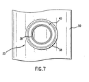
- Fig. 7 is a diagrammatic front view of a tool and packer according to one preferred embodiment of the invention.
- Fig. 1 shows
tool 50, or testing device, having a prior art anchoring apparatus.Tool 50 is positioned withinborehole 10 for taking appropriate measurements.Tool 50 is suspended oncable 48 insideborehole 10 which is preferably lined withcasing 7 material, such as steel.Cement 12 preferably supportscasing 7 and dividescasing 7 fromformation 15.Borehole 10 is typically filled with water or a completion fluid. -
Tool 50 is raised and lowered throughborehole 10 to the proper level withinborehole 10 to accomplish specific predetermined tasks.Tool 50 preferably has a generally cylindrical body which preferably encloses various testing equipment, drilling equipment, pumping equipment and/or any other necessary equipment or apparatus for use in a natural gas or oil well. According to one preferred embodiment of this invention,tool 50 contains testing apparatus for testing andsampling formation 15 surroundingborehole 10 to determine the presence of retrievable natural resources. In this preferred embodiment of the invention,tool 50 is anchored with respect tocasing 7 inborehole 10 and measures relevant variables used to determine the nature offormation 15 surroundingborehole 10. - Fig. 2 shows a top view of a prior art anchoring apparatus comprising
anchor piston 54 andpacker 35. One ormore anchor pistons 54 are positioned with respect totool 50 which is preferably a cylindrical or generally elongated element.Anchor pistons 54 are radially positioned with respect totool 50 and mechanically project away fromtool 50 or retract towardtool 50, depending upon an electronic signal. Preferably, prior art anchoring apparatus also comprisepacker 35 positioned on an opposite side fromanchor pistons 54. Asanchor pistons 54 are mechanically projected away fromtool 50 and againstcasing 7,anchor pistons 54force packer 35 againstcasing 7 forming a pressure-tight seal betweentool 50 andcasing 7 and maintaining a fixed vertical position oftool 50 with respect tocasing 7. Afterpacker 35 is sealed againstcasing 7, an internal portion oftool 50 is co-operable withcasing 7, ideally without risk of contamination from completion fluid or water inborehole 10. - As shown in Fig. 2, the prior art configuration of
anchor piston 54 andpacker 35 may result in atool 50 position which is misaligned with respect to animaginary centerline 32 withinborehole 10. Such misalignment, often 6°-7°, may result in incomplete contact betweenpacker 35 andcasing 7 thus causing an incomplete seal betweenpacker 35 andcasing 7. An incomplete seal may cause damage and contamina-tion of internal components oftool 50 from completion fluid, water, dirt, oil and other contaminants thus resulting in costly repairs or replacement. Amisaligned tool 50 may also result in inaccurate or incomplete testing measurements and data because of a longer measurement path toformation 15 throughcasing 7 andcement 12. - An apparatus for anchoring
tool 50 withinborehole 10 according to one preferred embodiment of this invention is shown in Fig. 3. As shown in Fig. 3,anchor shoe 25 is preferably associated withpiston 20, either directly, or through an intermediate connection. Also as shown in Fig. 3,packer 35 is also connected with respect totool 50, on an opposite side fromanchor shoe 25. - Fig. 6 shows anchor
shoe 25 which preferably includes leadingedge 28 having an outwardly curved surface. Such curved surface preferably has an apex approximately at a center ofanchor shoe 25. In one preferred embodiment of the invention, the curved surface roughly corresponds with the curved internal surface ofborehole 10. This preferred embodiment ofanchor shoe 25 prevents exterior edges of leadingedge 28 from digging intocasing 7 withinborehole 10. - In one preferred embodiment of this invention, shown in Figs. 3, 5 and 6,
anchor shoe 25 comprises penetration means 27 for engagement withborehole 10. Preferably, penetration means 27 comprises a plurality ofrollers 30.Rollers 30 are preferably wheels, discs or other configuration which will roll across a hard surface. Penetration means 27 may alternatively comprise alternative configurations which will likewise roll or glide across hard surfaces. - According to one preferred embodiment of this invention, penetration means 27, such as
rollers 30, are connected with respect to leadingedge 28 ofanchor shoe 25. Preferably, at least oneroller 30 is positioned on each side of the center ofanchor shoe 25. Positioning at least oneroller 30, and preferably an equal amount ofrollers 30, on each side of the center, or the approximate center, ofanchor shoe 25 maintainsanchor shoe 25 in a centered position with respect toborehole 10. In a preferred embodiment of the invention shown in Fig. 5, one set of threerollers 30 is positioned in each of four corners of leadingedge 28 ofanchor shoe 25. Such an arrangement of four sets ofrollers 30 further maintainsanchor shoe 25 in a centered position with respect toborehole 10 and prevents excessive wear on eachroller 30. - In one preferred embodiment of this invention shown in Fig. 5, at least one
roller 30 comprises a wheel having a generally sharpouter periphery 31.Roller 30 is preferably constructed from a rigid, corrosion-resistant material such as steel. The generally sharpouter periphery 31 is preferably resistant to dulling. In a preferred embodiment of this invention,outer periphery 31 has a shallow cutting edge. A shallow cutting edge prevents generation of a flat spot ofouter periphery 31 due to wear or a hard spot incasing 7. Such a flat spot inouter periphery 31 ofroller 30 would preventroller 30 from performing in an optimal manner. - In one preferred embodiment of this invention shown in Fig. 4,
packer 35 is connected with respect to a surface oftool 50.Packer 35 is preferably connected with respect totool 50 on an opposite surface as the one ormore pistons 20 and anchor shoes 25.Packer 35 preferably contains a rigid member and, in one preferred embodiment of this invention, a sealing member. - As shown in Figs. 4 and 7, the rigid member of
packer 35 comprises a plurality ofconcentric rings 38. Concentric rings 38 are preferably constructed from a rigid, corrosion-resistant material such as steel. Concentric rings 38 preferably each have a sharpened leading edge. - In one preferred embodiment of this invention, the sealing member of
packer 35 further comprises at least oneflexible gasket 40 connected with respect to at least oneconcentric ring 38.Gasket 40 may comprise an O-ring or other sealing member known to those having ordinary skill in the art. Preferablygasket 40 is positioned around a perimeter of one or moreconcentric ring 38.Gasket 40 is preferably of similar thickness asconcentric ring 38. - In one preferred embodiment of this invention,
packer 35 comprises a plurality ofconcentric rings 38 and a plurality ofgaskets 40, eachgasket 40 positioned adjacent eachconcentric ring 38. Such arrangement permitspacker 35 to both penetrate internal surface orcasing 7 ofborehole 10 and seal an area within the perimeter ofconcentric rings 38 with respect toborehole 10. - In a method for anchoring
tool 50 withinborehole 10 according to a preferred embodiment of this invention,piston 20 is extended away fromtool 50 toward the internal surface orcasing 7 ofborehole 10.Piston 20 extends outward fromtool 50 thus forcinganchor shoe 25 into engagement with the internal surface, orcasing 7, ofborehole 10. -
Anchor shoe 25, through sharpened outer periphery ofrollers 30, preferably penetrates the internal surface orcasing 7 ofborehole 10. Such penetration, and the extension ofpiston 20 into engagement with the internal surface orcasing 7 ofborehole 10, fixestool 50 into a vertical position with respect toborehole 10. - Fig. 3 shows a top view of an anchoring apparatus according to one preferred embodiment of this invention, comprising
piston 20,anchor shoe 25 andpacker 35. One ormore pistons 20, each having at least oneanchor shoe 25, are positioned with respect totool 50 which is preferably a cylindrical or generally elongated element.Pistons 20 are preferably radially positioned with respect totool 50 and mechanically project away fromtool 50 or retract towardtool 50, depending upon a signal sent by the user. - When
piston 20 is in a fully extended position,anchor shoe 25 engages with the internal surface orcasing 7 ofborehole 10. Preferably,rollers 30 or other penetration means 27 engage withcasing 7 in a non-destructive manner, thus maintaining the integrity ofcasing 7adjacent anchor shoe 25. -
Packer 35 preferably engages with the internal surface orcasing 7 ofborehole 10 on an opposite side oftool 50 frompiston 20 andanchor shoe 25. Whenpiston 20 is in an extended position andanchor shoe 25 is engaged with the internal surface ofborehole 10,packer 35 is likewise engaged with the internal surface orcasing 7 ofborehole 10. Similar torollers 30,packer 35 preferably penetrates the internal surface orcasing 7 ofborehole 10. Aspistons 20 mechanically project away fromtool 50 and againstcasing 7,pistons 20force packer 35 againstcasing 7 forming a pressure-tight seal betweentool 50 andcasing 7 and maintaining a fixed vertical position oftool 50 with respect tocasing 7. Afterpacker 35 is sealed againstcasing 7, an internal portion oftool 50, also called a tool string, is co-operable withcasing 7 without risk of contamination from completion fluid or water inborehole 10. - As shown in Fig. 3 and contrary to the prior art device shown in Fig. 2, the arrangement of
anchor shoe 25, including curvedleading edge 28 androllers 30, alignspacker 35 with respect to animaginary centerline 32 throughborehole 10. Such alignment promotes a good seal between the internal components oftool 50 andformation 15. According to a preferred embodiment of this invention,tool 50 will be aligned within at least 2° of thecenterline 32 ofborehole 10. Alignment also results in complete contact betweenpacker 35 andcasing 7 thus avoiding damage and contamination of internal components oftool 50 from completion fluid, water, dirt, oil and other contaminants thus resulting in costly repairs or replacement. An alignedtool 50 also results in accurate and complete testing measurements and data fromformation 15. - Preferably,
tool 50 is fixed into a vertical position by the penetration of bothpacker 35 andanchor shoe 35. Such penetration enablestool 50 to maintain a vertical position despite severe pressures and turbulent fluid flows withinborehole 10 and despite the internal movement of testing equipment withintool 50. The level of penetration and thus the level of stability oftool 50 may be controlled by varying the force exerted bypiston 20 with respect to the internal surface orcasing 7 ofborehole 10. The level of penetration must be determined by balancing the required stability against the potential for damage ofanchor shoe 25,packer 35 and the internal surface orcasing 7 ofborehole 10. - While in the foregoing specification this invention has been described in relation to certain preferred embodiments thereof, and many details have been set forth for purpose of illustration, it is to be understood, as aforementioned, that this invention is susceptible to additional embodiments and that certain of the details described herein can be varied considerably without departing from the basic principles of the invention expressed herein.
Claims (16)
- An apparatus for anchoring a tool (50) within a cased borehole (10), the apparatus comprising at least one piston (20) connected with respect to the tool (50) and a packer (35);
an anchor shoe (25) associated with the piston (20), the anchor shoe (25) having a leading edge (28) having an outwardly curved surface having an apex approximately at a center of the anchor shoe, the apparatus characterized in that said anchor shoe further comprises penetration means (27) for engagement with the cased borehole (10); and
the packer (35) is connected with respect to a surface of the tool, the packer (35) having a rigid component. - The apparatus of claim 1 wherein the penetration means (27) comprises a plurality of rollers (30) connected with respect to the lading edge (28) of the anchor shoe (25).
- The apparatus of claim 2 wherein at least one roller of the rollers (30) is positioned on each side of the center of the anchor shoe (25).
- The apparatus of claim 1 wherein the penetration means (27) comprises a plurality of rollers (30) connected with respect to a leading edge (28) of the anchor shoe (25).
- The apparatus of claim 4 wherein at least one roller (30) of the rollers (25) comprises a wheel having a generally sharp outer periphery (31).
- The apparatus of one of the preceding claims wherein the rigid component of the packer (35) comprises a plurality of concentric rings (38) each having a sharpened leading edge.
- The apparatus of one of the preceding claims wherein the packer (35) comprises a sealing member and a rigid member having a generally sharp leading edge.
- The apparatus of claim 6 or 7 wherein the packer (35) further comprises at least one flexible gasket member (40) connected with respect to at least one concentric ring (38) of the concentric rings (38).
- The apparatus of one of the preceding claims, wherein the anchor shoe (25) comprises a plurality of rollers (30) connected with respect to the leading edge (28) of the anchor shoe (25).
- The apparatus of one of claims 7 to 9 wherein the sealing member comprises at least one O-ring connected with respect to the rigid member.
- The apparatus of one of claims 7 to 10 wherein the rigid member comprises two or more concentric rings (38) connected with respect to the sealing member.
- The apparatus of one of claims 7 to 11 wherein the sealing member is engaged with at least one concentric ring member.
- The apparatus of one of the preceding claims,
the anchor shoe (25) having a generally curved leading surface and a centerline passing through an approximate apex of the anchor shoe (25), and
at least one penetration means (27) positioned on each side of the centerline of the anchor shoe (25). - The apparatus of claim 13 wherein each of the rollers (30) having an edge extending from the curved leading surface of the anchor shoe (25).
- A method for anchoring a tool (50) within a cased borehole (10), the method comprising:extending at least one piston (20) connected with respect to the tool (50) toward an internal surface of the cased borehole (10) and penetrating an opposing internal surface of the cased borehole (10) with a packer (35) connected with respect to the tool (50),characterized by
penetrating the internal surface of the cased borehole (10) with an anchor shoe (25) associated with the piston (20); and
aligning the packer (35) with respect to the opposing internal surface of the cased borehole (10) with a plurality of roller (35) or glide configuration connected with respect to the anchor shoe (25). - The method of claim 15 further comprising sealing an area between the tool (50) and the internal surface of the cased borehole (10).
Applications Claiming Priority (3)
| Application Number | Priority Date | Filing Date | Title |
|---|---|---|---|
| US132917 | 1998-08-12 | ||
| US09/132,917 US6119782A (en) | 1998-08-12 | 1998-08-12 | Method and apparatus for anchoring a tool within a cased borehole |
| PCT/US1999/016660 WO2000009854A1 (en) | 1998-08-12 | 1999-07-23 | Method and apparatus for anchoring a tool within a cased borehole |
Publications (2)
| Publication Number | Publication Date |
|---|---|
| EP1108114A1 EP1108114A1 (en) | 2001-06-20 |
| EP1108114B1 true EP1108114B1 (en) | 2005-09-21 |
Family
ID=22456161
Family Applications (1)
| Application Number | Title | Priority Date | Filing Date |
|---|---|---|---|
| EP99935870A Expired - Lifetime EP1108114B1 (en) | 1998-08-12 | 1999-07-23 | Method and apparatus for anchoring a tool within a cased borehole |
Country Status (7)
| Country | Link |
|---|---|
| US (1) | US6119782A (en) |
| EP (1) | EP1108114B1 (en) |
| AT (1) | ATE305080T1 (en) |
| CA (1) | CA2341060C (en) |
| DE (1) | DE69927391T2 (en) |
| NO (1) | NO318986B1 (en) |
| WO (1) | WO2000009854A1 (en) |
Families Citing this family (9)
| Publication number | Priority date | Publication date | Assignee | Title |
|---|---|---|---|---|
| US7048089B2 (en) * | 2003-05-07 | 2006-05-23 | Battelle Energy Alliance, Llc | Methods and apparatus for use in detecting seismic waves in a borehole |
| US7380599B2 (en) * | 2004-06-30 | 2008-06-03 | Schlumberger Technology Corporation | Apparatus and method for characterizing a reservoir |
| WO2010008684A2 (en) * | 2008-07-15 | 2010-01-21 | Schlumberger Canada Limited | Apparatus and methods for characterizing a reservoir |
| US8408296B2 (en) | 2010-08-18 | 2013-04-02 | Schlumberger Technology Corporation | Methods for borehole measurements of fracturing pressures |
| US8397817B2 (en) | 2010-08-18 | 2013-03-19 | Schlumberger Technology Corporation | Methods for downhole sampling of tight formations |
| CA3153255C (en) * | 2014-06-17 | 2024-01-02 | Petrojet Canada Inc. | Hydraulic drilling systems and methods |
| EP3502411B1 (en) * | 2014-08-21 | 2021-02-24 | Agat Technology AS | Anchoring module for well tools |
| NO20141020A1 (en) * | 2014-08-21 | 2016-02-22 | Agat Tech As | Anchoring device for well tools |
| US20250020824A1 (en) * | 2023-07-14 | 2025-01-16 | Halliburton Energy Services, Inc. | Through casing sensor placement |
Family Cites Families (18)
| Publication number | Priority date | Publication date | Assignee | Title |
|---|---|---|---|---|
| US2313176A (en) * | 1940-07-19 | 1943-03-09 | Peter P Shelby | Well tester |
| US2588717A (en) * | 1946-05-25 | 1952-03-11 | Stanolind Oil & Gas Co | Apparatus for measuring dips of well strata |
| US3244253A (en) * | 1959-12-23 | 1966-04-05 | Schlumberger Well Surv Corp | Acoustic logging systems |
| US3344860A (en) * | 1965-05-17 | 1967-10-03 | Schlumberger Well Surv Corp | Sidewall sealing pad for borehole apparatus |
| US4050529A (en) * | 1976-03-25 | 1977-09-27 | Kurban Magomedovich Tagirov | Apparatus for treating rock surrounding a wellbore |
| US4158388A (en) * | 1977-06-20 | 1979-06-19 | Pengo Industries, Inc. | Method of and apparatus for squeeze cementing in boreholes |
| US4369654A (en) * | 1980-12-23 | 1983-01-25 | Hallmark Bobby J | Selective earth formation testing through well casing |
| US4470456A (en) * | 1983-02-22 | 1984-09-11 | Moutray Iii Waldo W | Borehole sampling tool |
| EP0178784A3 (en) * | 1984-09-13 | 1988-06-29 | Atlantic Richfield Company | Horizontally stabilized borehole sonde |
| FR2609100B1 (en) * | 1986-12-24 | 1990-09-14 | Inst Francais Du Petrole | PROBE AND MULTI-DIRECTIONAL ANCHORING DEVICE IN A WELL |
| US5062482A (en) * | 1989-08-07 | 1991-11-05 | Alberta Oil Sands Technology And Research Authority | Piezometer actuator device and method for its installation in a borehole |
| US5056595A (en) * | 1990-08-13 | 1991-10-15 | Gas Research Institute | Wireline formation test tool with jet perforator for positively establishing fluidic communication with subsurface formation to be tested |
| US5220959A (en) * | 1991-09-24 | 1993-06-22 | The Gates Rubber Company | Gripping inflatable packer |
| NO941992D0 (en) * | 1994-05-30 | 1994-05-30 | Norsk Hydro As | Injector for injecting tracer into an oil and / or gas reservoir |
| US5585555A (en) * | 1995-01-24 | 1996-12-17 | Geokon, Inc. | Borehole strainmeter |
| US5542473A (en) * | 1995-06-01 | 1996-08-06 | Pringle; Ronald E. | Simplified sealing and anchoring device for a well tool |
| US5692565A (en) * | 1996-02-20 | 1997-12-02 | Schlumberger Technology Corporation | Apparatus and method for sampling an earth formation through a cased borehole |
| US6026915A (en) * | 1997-10-14 | 2000-02-22 | Halliburton Energy Services, Inc. | Early evaluation system with drilling capability |
-
1998
- 1998-08-12 US US09/132,917 patent/US6119782A/en not_active Expired - Lifetime
-
1999
- 1999-07-23 WO PCT/US1999/016660 patent/WO2000009854A1/en not_active Ceased
- 1999-07-23 EP EP99935870A patent/EP1108114B1/en not_active Expired - Lifetime
- 1999-07-23 CA CA002341060A patent/CA2341060C/en not_active Expired - Fee Related
- 1999-07-23 AT AT99935870T patent/ATE305080T1/en not_active IP Right Cessation
- 1999-07-23 DE DE69927391T patent/DE69927391T2/en not_active Expired - Lifetime
-
2001
- 2001-02-09 NO NO20010681A patent/NO318986B1/en not_active IP Right Cessation
Also Published As
| Publication number | Publication date |
|---|---|
| WO2000009854A1 (en) | 2000-02-24 |
| ATE305080T1 (en) | 2005-10-15 |
| NO20010681L (en) | 2001-04-06 |
| CA2341060C (en) | 2005-04-26 |
| NO318986B1 (en) | 2005-05-30 |
| CA2341060A1 (en) | 2000-02-24 |
| US6119782A (en) | 2000-09-19 |
| DE69927391T2 (en) | 2006-05-11 |
| DE69927391D1 (en) | 2006-02-02 |
| EP1108114A1 (en) | 2001-06-20 |
| NO20010681D0 (en) | 2001-02-09 |
Similar Documents
| Publication | Publication Date | Title |
|---|---|---|
| US5667023A (en) | Method and apparatus for drilling and completing wells | |
| EP1050661B1 (en) | Improvements relating to subsea drilling of boreholes | |
| USRE38642E1 (en) | Downhole equipment, tools and assembly procedures for the drilling, tie-in and completion of vertical cased oil wells connected to liner-equipped multiple drainholes | |
| US20020060096A1 (en) | Apparatus to actuate downhole tool | |
| Haimson | Crustal stress in the Michigan Basin | |
| Alberty et al. | Mechanisms of shallow waterflows and drilling practices for intervention | |
| EP2766569B1 (en) | Formation pressure sensing system | |
| GB2275282A (en) | Abandonment of sub-sea wells | |
| Haimson¹ | A Simple Method for Estimating In Situ | |
| GB2422396A (en) | Instrumentation for a downhole deployment valve | |
| AU2010309542A1 (en) | Expandable liner tieback connection | |
| CA2276222C (en) | High pressure internal sleeve for use with easily drillable exit ports | |
| NO316041B1 (en) | Device for distance measurement in a borehole and method for the same | |
| US4529036A (en) | Method of determining subterranean formation fracture orientation | |
| US6119782A (en) | Method and apparatus for anchoring a tool within a cased borehole | |
| Mainguy et al. | Explaining sustained “A”-annulus pressure in major north sea high-pressure/high-temperature fields | |
| US5816326A (en) | Uphole disposal tool for water producing gas wells | |
| Staheli et al. | Installation of pipelines beneath levees using horizontal directional drilling | |
| US4803874A (en) | Device and method for determining the orientation of fractures in a geological formation | |
| CN101027457A (en) | Permanently eccentered formation tester | |
| US5967232A (en) | Borehole-conformable tool for in-situ stress measurements | |
| CA2241194A1 (en) | Determination of fluid influx or efflux | |
| Dutt et al. | Recent advances in deepwater Gulf of Mexico geotechnical investigations | |
| JP3053563B2 (en) | Hydraulic testing method at large depth, drilling rig and packer for the test | |
| US12553325B2 (en) | Method of controlling tensile-splitting and hydro-shearing parameters during completion of enhanced geothermal system wells |
Legal Events
| Date | Code | Title | Description |
|---|---|---|---|
| PUAI | Public reference made under article 153(3) epc to a published international application that has entered the european phase |
Free format text: ORIGINAL CODE: 0009012 |
|
| 17P | Request for examination filed |
Effective date: 20010312 |
|
| AK | Designated contracting states |
Kind code of ref document: A1 Designated state(s): AT BE CH CY DE DK ES FI FR GB GR IE IT LI LU MC NL PT SE |
|
| 17Q | First examination report despatched |
Effective date: 20030917 |
|
| GRAP | Despatch of communication of intention to grant a patent |
Free format text: ORIGINAL CODE: EPIDOSNIGR1 |
|
| GRAS | Grant fee paid |
Free format text: ORIGINAL CODE: EPIDOSNIGR3 |
|
| GRAA | (expected) grant |
Free format text: ORIGINAL CODE: 0009210 |
|
| AK | Designated contracting states |
Kind code of ref document: B1 Designated state(s): AT BE CH CY DE DK ES FI FR GB GR IE IT LI LU MC NL PT SE |
|
| PG25 | Lapsed in a contracting state [announced via postgrant information from national office to epo] |
Ref country code: NL Free format text: LAPSE BECAUSE OF FAILURE TO SUBMIT A TRANSLATION OF THE DESCRIPTION OR TO PAY THE FEE WITHIN THE PRESCRIBED TIME-LIMIT Effective date: 20050921 Ref country code: LI Free format text: LAPSE BECAUSE OF FAILURE TO SUBMIT A TRANSLATION OF THE DESCRIPTION OR TO PAY THE FEE WITHIN THE PRESCRIBED TIME-LIMIT Effective date: 20050921 Ref country code: IT Free format text: LAPSE BECAUSE OF FAILURE TO SUBMIT A TRANSLATION OF THE DESCRIPTION OR TO PAY THE FEE WITHIN THE PRESCRIBED TIME-LIMIT;WARNING: LAPSES OF ITALIAN PATENTS WITH EFFECTIVE DATE BEFORE 2007 MAY HAVE OCCURRED AT ANY TIME BEFORE 2007. THE CORRECT EFFECTIVE DATE MAY BE DIFFERENT FROM THE ONE RECORDED. Effective date: 20050921 Ref country code: FI Free format text: LAPSE BECAUSE OF FAILURE TO SUBMIT A TRANSLATION OF THE DESCRIPTION OR TO PAY THE FEE WITHIN THE PRESCRIBED TIME-LIMIT Effective date: 20050921 Ref country code: CH Free format text: LAPSE BECAUSE OF FAILURE TO SUBMIT A TRANSLATION OF THE DESCRIPTION OR TO PAY THE FEE WITHIN THE PRESCRIBED TIME-LIMIT Effective date: 20050921 Ref country code: BE Free format text: LAPSE BECAUSE OF FAILURE TO SUBMIT A TRANSLATION OF THE DESCRIPTION OR TO PAY THE FEE WITHIN THE PRESCRIBED TIME-LIMIT Effective date: 20050921 Ref country code: AT Free format text: LAPSE BECAUSE OF FAILURE TO SUBMIT A TRANSLATION OF THE DESCRIPTION OR TO PAY THE FEE WITHIN THE PRESCRIBED TIME-LIMIT Effective date: 20050921 |
|
| REG | Reference to a national code |
Ref country code: GB Ref legal event code: FG4D |
|
| REG | Reference to a national code |
Ref country code: CH Ref legal event code: EP |
|
| REG | Reference to a national code |
Ref country code: IE Ref legal event code: FG4D |
|
| REF | Corresponds to: |
Ref document number: 69927391 Country of ref document: DE Date of ref document: 20051027 Kind code of ref document: P |
|
| PG25 | Lapsed in a contracting state [announced via postgrant information from national office to epo] |
Ref country code: SE Free format text: LAPSE BECAUSE OF FAILURE TO SUBMIT A TRANSLATION OF THE DESCRIPTION OR TO PAY THE FEE WITHIN THE PRESCRIBED TIME-LIMIT Effective date: 20051221 Ref country code: GR Free format text: LAPSE BECAUSE OF FAILURE TO SUBMIT A TRANSLATION OF THE DESCRIPTION OR TO PAY THE FEE WITHIN THE PRESCRIBED TIME-LIMIT Effective date: 20051221 Ref country code: DK Free format text: LAPSE BECAUSE OF FAILURE TO SUBMIT A TRANSLATION OF THE DESCRIPTION OR TO PAY THE FEE WITHIN THE PRESCRIBED TIME-LIMIT Effective date: 20051221 |
|
| PG25 | Lapsed in a contracting state [announced via postgrant information from national office to epo] |
Ref country code: ES Free format text: LAPSE BECAUSE OF FAILURE TO SUBMIT A TRANSLATION OF THE DESCRIPTION OR TO PAY THE FEE WITHIN THE PRESCRIBED TIME-LIMIT Effective date: 20060101 |
|
| REF | Corresponds to: |
Ref document number: 69927391 Country of ref document: DE Date of ref document: 20060202 Kind code of ref document: P |
|
| PG25 | Lapsed in a contracting state [announced via postgrant information from national office to epo] |
Ref country code: PT Free format text: LAPSE BECAUSE OF FAILURE TO SUBMIT A TRANSLATION OF THE DESCRIPTION OR TO PAY THE FEE WITHIN THE PRESCRIBED TIME-LIMIT Effective date: 20060221 |
|
| NLV1 | Nl: lapsed or annulled due to failure to fulfill the requirements of art. 29p and 29m of the patents act | ||
| REG | Reference to a national code |
Ref country code: CH Ref legal event code: PL |
|
| ET | Fr: translation filed | ||
| REG | Reference to a national code |
Ref country code: GB Ref legal event code: 732E |
|
| PG25 | Lapsed in a contracting state [announced via postgrant information from national office to epo] |
Ref country code: IE Free format text: LAPSE BECAUSE OF NON-PAYMENT OF DUE FEES Effective date: 20060724 |
|
| PLBE | No opposition filed within time limit |
Free format text: ORIGINAL CODE: 0009261 |
|
| STAA | Information on the status of an ep patent application or granted ep patent |
Free format text: STATUS: NO OPPOSITION FILED WITHIN TIME LIMIT |
|
| PG25 | Lapsed in a contracting state [announced via postgrant information from national office to epo] |
Ref country code: MC Free format text: LAPSE BECAUSE OF NON-PAYMENT OF DUE FEES Effective date: 20060731 |
|
| 26N | No opposition filed |
Effective date: 20060622 |
|
| REG | Reference to a national code |
Ref country code: FR Ref legal event code: TP |
|
| REG | Reference to a national code |
Ref country code: IE Ref legal event code: MM4A |
|
| PG25 | Lapsed in a contracting state [announced via postgrant information from national office to epo] |
Ref country code: LU Free format text: LAPSE BECAUSE OF NON-PAYMENT OF DUE FEES Effective date: 20060723 |
|
| PG25 | Lapsed in a contracting state [announced via postgrant information from national office to epo] |
Ref country code: CY Free format text: LAPSE BECAUSE OF FAILURE TO SUBMIT A TRANSLATION OF THE DESCRIPTION OR TO PAY THE FEE WITHIN THE PRESCRIBED TIME-LIMIT Effective date: 20050921 |
|
| REG | Reference to a national code |
Ref country code: FR Ref legal event code: PLFP Year of fee payment: 18 |
|
| REG | Reference to a national code |
Ref country code: FR Ref legal event code: PLFP Year of fee payment: 19 |
|
| PGFP | Annual fee paid to national office [announced via postgrant information from national office to epo] |
Ref country code: FR Payment date: 20170726 Year of fee payment: 19 Ref country code: DE Payment date: 20170727 Year of fee payment: 19 |
|
| PGFP | Annual fee paid to national office [announced via postgrant information from national office to epo] |
Ref country code: GB Payment date: 20180727 Year of fee payment: 20 |
|
| REG | Reference to a national code |
Ref country code: DE Ref legal event code: R119 Ref document number: 69927391 Country of ref document: DE |
|
| PG25 | Lapsed in a contracting state [announced via postgrant information from national office to epo] |
Ref country code: DE Free format text: LAPSE BECAUSE OF NON-PAYMENT OF DUE FEES Effective date: 20190201 Ref country code: FR Free format text: LAPSE BECAUSE OF NON-PAYMENT OF DUE FEES Effective date: 20180731 |
|
| REG | Reference to a national code |
Ref country code: GB Ref legal event code: PE20 Expiry date: 20190722 |
|
| PG25 | Lapsed in a contracting state [announced via postgrant information from national office to epo] |
Ref country code: GB Free format text: LAPSE BECAUSE OF EXPIRATION OF PROTECTION Effective date: 20190722 |