EP1107648A2 - Circular film heater - Google Patents
Circular film heater Download PDFInfo
- Publication number
- EP1107648A2 EP1107648A2 EP00850200A EP00850200A EP1107648A2 EP 1107648 A2 EP1107648 A2 EP 1107648A2 EP 00850200 A EP00850200 A EP 00850200A EP 00850200 A EP00850200 A EP 00850200A EP 1107648 A2 EP1107648 A2 EP 1107648A2
- Authority
- EP
- European Patent Office
- Prior art keywords
- bus bars
- segments
- heater according
- resistive
- connected along
- Prior art date
- Legal status (The legal status is an assumption and is not a legal conclusion. Google has not performed a legal analysis and makes no representation as to the accuracy of the status listed.)
- Withdrawn
Links
Images


Classifications
-
- H—ELECTRICITY
- H05—ELECTRIC TECHNIQUES NOT OTHERWISE PROVIDED FOR
- H05B—ELECTRIC HEATING; ELECTRIC LIGHT SOURCES NOT OTHERWISE PROVIDED FOR; CIRCUIT ARRANGEMENTS FOR ELECTRIC LIGHT SOURCES, IN GENERAL
- H05B3/00—Ohmic-resistance heating
- H05B3/20—Heating elements having extended surface area substantially in a two-dimensional plane, e.g. plate-heater
- H05B3/22—Heating elements having extended surface area substantially in a two-dimensional plane, e.g. plate-heater non-flexible
- H05B3/26—Heating elements having extended surface area substantially in a two-dimensional plane, e.g. plate-heater non-flexible heating conductor mounted on insulating base
- H05B3/265—Heating elements having extended surface area substantially in a two-dimensional plane, e.g. plate-heater non-flexible heating conductor mounted on insulating base the insulating base being an inorganic material, e.g. ceramic
-
- H—ELECTRICITY
- H05—ELECTRIC TECHNIQUES NOT OTHERWISE PROVIDED FOR
- H05B—ELECTRIC HEATING; ELECTRIC LIGHT SOURCES NOT OTHERWISE PROVIDED FOR; CIRCUIT ARRANGEMENTS FOR ELECTRIC LIGHT SOURCES, IN GENERAL
- H05B3/00—Ohmic-resistance heating
- H05B3/68—Heating arrangements specially adapted for cooking plates or analogous hot-plates
- H05B3/74—Non-metallic plates, e.g. vitroceramic, ceramic or glassceramic hobs, also including power or control circuits
- H05B3/748—Resistive heating elements, i.e. heating elements exposed to the air, e.g. coil wire heater
-
- H—ELECTRICITY
- H05—ELECTRIC TECHNIQUES NOT OTHERWISE PROVIDED FOR
- H05B—ELECTRIC HEATING; ELECTRIC LIGHT SOURCES NOT OTHERWISE PROVIDED FOR; CIRCUIT ARRANGEMENTS FOR ELECTRIC LIGHT SOURCES, IN GENERAL
- H05B2203/00—Aspects relating to Ohmic resistive heating covered by group H05B3/00
- H05B2203/013—Heaters using resistive films or coatings
-
- H—ELECTRICITY
- H05—ELECTRIC TECHNIQUES NOT OTHERWISE PROVIDED FOR
- H05B—ELECTRIC HEATING; ELECTRIC LIGHT SOURCES NOT OTHERWISE PROVIDED FOR; CIRCUIT ARRANGEMENTS FOR ELECTRIC LIGHT SOURCES, IN GENERAL
- H05B2203/00—Aspects relating to Ohmic resistive heating covered by group H05B3/00
- H05B2203/017—Manufacturing methods or apparatus for heaters
Definitions
- This invention relates generally to the field of heating and cooking and specifically to a resistance heater.
- Electrical resistance heating films are used in various applications.
- the resistive film is applied on a substrate, which may provide a heating surface or may be the surface to be heated.
- a controlled voltage or current is applied to the film to effect the creation of heat energy.
- Examples of film heaters and controllers therefor are described in U.S. Patents Nos. 4,233,497 to Lowell, 4,384,192 to Lowell, 4,973,826 to Baudry, 5,160,830 to Kicherer and 5,616,266 to Cooper.
- U.S. Patent Application No. 09/067,135 also shows a film heater and related components.
- Range cook tops for cooking food use electric heaters. It is desirable to provide a durable surface for supporting objects so that the objects can be heated efficiently and reliably. Heating of the surface should be limited to a desired area.
- the invention provides a heater including a substrate having a heating zone.
- a resistive layer is disposed on at least part of the substrate heating zone and forms an annular heating element divided into arcuate segments. Conductive bus bars electrically connecting the arcuate segments in series.
- the bus bars are disposed on edges of the arcuate segments.
- the bus bars are respectively connected along inner and outer edges of the arcuate segments.
- a first one of the bus bars is connected along a first edge of a first one of the arcuate segments and a second one of the bus bars is connected along a second edge of the first arcuate segment opposite the first edge and along an edge of a second one of the arcuate segments.
- the resistive layer includes first, second, third, and fourth of the arcuate segments, a first one of the bus bars is connected along an outer edge of the first segment, a second one of the bus bars is connected along inner edges of the first and second segments, a third one of the bus bars is connected along outer edges of the second and third segments, a fourth one of the bus bars is connected along inner edges of the third and fourth segments, and a fifth one of the bus bars is connected along an outer edge of the fourth segment.
- the first and fifth bus bars are connected to a power source.
- the resistive layer includes first, second, third, fourth, fifth, sixth, seventh, and eighth of the arcuate segments, a first one of the bus bars is connected along an inner edge of the first segment, a second one of the bus bars is connected along outer edges of the first and second segments, a third one of the bus bars is connected along inner edges of the second and third segments, a fourth one of the bus bars is connected along outer edges of the third and fourth segments, a fifth one of the bus bars is connected along inner edges of the fourth and fifth segments, a sixth one of the bus bars is connected along outer edges of the fifth and sixth segments, a seventh one of the bus bars is connected along inner edges of the sixth and seventh segments, an eighth one of the bus bars is connected along outer edges of the seventh and eighth segments, and a ninth one of the bus bars is connected along an inner edge of the eighth segment.
- the first and ninth bus bars are connected to a power source.
- the resistive layer also includes a separate element disposed within the annular element and conductive bus bars disposed along opposite edges of the separate element.
- the separate element bus bars are connected to the annular element bus bars so that the separate element is electrically connected in parallel with the annular element.
- the separate element bus bars are arranged so that power to the separate element can be controlled separately from the annular element.
- a resistive lead is connected from a conductive element disposed adjacent the resistive layer to a temperature sensor.
- the conductive element is one of the bus bars.
- a conductive lead is connected to the conductive element.
- Gaps between different segments of the resistive layer are filled with insulating material.
- a dielectric layer is disposed between the resistive layer and the substrate.
- the invention provides a heater including a substrate having a heating zone.
- a resistive layer is disposed on at least part of the substrate heating zone and forms an annular heating element divided into arcuate segments and a rectangular element disposed within the annular element.
- Annular element conductive bus bars are disposed on edges of the arcuate segments electrically connecting the arcuate segments in series, wherein a first one of the annular element bus bars is connected along a first edge of a first one of the arcuate segments and a second one of the annular element bus bars is connected along a second edge of the first arcuate segment opposite the first edge and along an edge of a second one of the arcuate segments, a last one of the annular element bus bars is connected along an edge of a last one of the arcuate segments in the series, and the first and last annular element bus bars are connected to a power source.
- Rectangular element conductive bus bars are disposed along opposite edges of the rectangular element and connected to the power source.
- the rectangular element bus bars are connected to the annular element bus bars so that the rectangular element is electrically connected in parallel with the annular element.
- the rectangular element bus bars are arranged so that power to the rectangular element can be controlled separately from the annular element.
- a resistive temperature sensing lead is connected to a conductive element disposed adjacent the resistive layer, wherein the temperature sensing leads are connected to a controller for monitoring the temperature of the heater.
- a heating apparatus such as a range cook top 10
- a heating apparatus includes a generally horizontal planar surface forming a substrate 12.
- a heating zone is formed on the substrate 12 and includes a resistive film layer 14 deposited on the substrate.
- a dielectric layer 16 can be disposed between the resistive film layer 14 and the substrate 12.
- a sealing layer 18 can be disposed over the resistive film 14.
- Fig. 1 is schematic and the relative thicknesses of the layers do not represent actual thicknesses. The components described above are described in more detail below and in U.S. Patent Application Ser. No. 08/800,738.
- the substrate 12 is preferably a thermal shock resistant, rigid, and planar structure having a low electrical conductivity.
- the substrate is suitable for supporting objects to be heated.
- the substrate 12 is supported by a frame of the range and forms the base of the cook top.
- the substrate 12 can be glass ceramic, such as Li 2 Al 2 Si 2 O 6 beta-quartz (LAS), available from Eurokera or Schott.
- LAS glass ceramic or Si 3 N 4 ceramic about 4.0 mm thick can be used in some cases.
- porcelain enameled (P-E) steel about 2.5 mm thick, that is, 2.0 mm of steel 12a with about 0.25 mm of porcelain enamel 12b on each side.
- materials suitable for use as the substrate 12 include, but are not limited to, porcelainized carbon steel, porcelainized ferritic stainless steel, aluminum oxide, glass ceramic commonly referred to as Ceran, Si 3 N 4 -ceramic, and combinations of the foregoing.
- the resistive film 14 is preferably a thin film of atmospheric chemical vapor deposition (ACVD) applied F-doped or Sb-doped SnO 2 able to withstand a power density of 1.5 to 14 W/cm 2 and a current density between 11,000 and 90,000 A/cm 2 .
- a preferred dopant for tin dioxide is 0.1 to 0.5 weight percent fluorine.
- the film has a surface resistance of 75 Ohms per square.
- a voltage applied across the film causes a current to flow through the film thereby heating the film.
- the thin film has a positive temperature coefficient (PTC) to prevent thermal run away.
- PTC positive temperature coefficient
- cermet-based thick film material a polymer-based thick film material, or any type of electrically resistive film or coating. Because its resistance varies as a function of temperature, the resistive film can also be used as a temperature sensor. Alternatively, a separate temperature sensor can be located at the heating zone for closed loop temperature control.
- the dielectric layer 16 is preferably a sol gel applied SiO 2 /Al 2 O 3 or a screen printed and fired glass layer.
- the dielectric layer preferably insulates the substrate from currents flowing in the resistive film 14 and has a dielectric constant of about 5 to 8 (at room temperature and 50-60Hz).
- the dielectric constant should be as low and as stable as possible over the operating temperature range of the heater, which is about 20°C to 500°C.
- the dielectric layer should not substantially limit heat conduction from the resistive film to the substrate. Other materials having the desired properties may also be suitable.
- Examples of such materials include titanium dioxide, inorganic high temperature cements, sealing glasses, sol gel applied ceramics such as zirconia applied as a sol gel, high temperature paint, plasma or flame sprayed ceramics, or combinations thereof.
- the dielectric material selected preferably has a coefficient of thermal expansion as close to the substrate 12 as possible.
- a specific example of a preferred material for the dielectric layer is a glass layer fused to a glass ceramic substrate. Such fusing can be performed at temperatures in the range of 600°C to 850°C. This can be applied via atmospheric chemical vapor deposition.
- a further specific example of a preferred material for the dielectric layer is a ceramic material, for instance an alumina-based ceramic material, that is plasma sprayed or HVOF sprayed.
- the sealing layer 18 is a heat resistant, rigid material having high electrical insulating properties and high heat conductivity.
- the sealing layer resists corrosion of the resistive layer.
- ACVD applied SiO 2 is used.
- Electrically conductive bus bars 20, such as cermet based silver thick film, are disposed on the resistive film layer 14 and preferably covered by the sealing layer 18.
- the thickness of each electrode 20 is from about 5 to about 25 micrometers.
- the bus bars are preferably about 1.5 mm wide.
- the bus bars 20 are connected to a power supply for providing a controlled current or voltage to the resistive film 14. The bus bar configurations and connections are discussed below.
- the cook top 10 includes several heating zones 22.
- Each heating zone 22 includes resistive film and bus bars disposed on the substrate as discussed above.
- the heating zones 22 are circular and correspond in size with conventional large and small cook top element sizes, for example, about 235 mm and 160 mm in diameter.
- the heating zone 22 is separated from the remaining area of the cook top 10 by a circumferential slot 24.
- the slot 24 thermally insulates the cook top 10 from the heating zone 22.
- the resistive film does not extend past the slot.
- the slot 24 is discontinuous, interrupted by circumferentially spaced tongues 25. The tongues provide mechanical support for the heating zone and can provide a path for running electrical connections, such as conductive bus bar layers.
- the electrical connections are connected to a power source through a controller.
- the tongues 25 are formed by leaving substrate material when the slot 24 is formed.
- the tongues have the same thickness as the substrate, but do not have porcelain enamel applied thereto expect where a path is provided for electrical conductors, wherein the enamel provides electrical insulation between the substrate and electrical conductors.
- One of the tongues 25a extends directly across the slot to serve as a bridge for simple routing of the bus bars.
- the other tongues 25 follow a serpentine path across the slot.
- the serpentine tongues allow for thermal expansion of the cook top elements.
- the width and number of tongues are selected to provide support for the physical loads placed on the heating zone.
- the tongues 25 can be separate parts, such as insulating fasteners, added to secure the heating zone to the cook top. Inserts and sealers are provided in the slots. These are described in more detail in U.S. Patent Application Ser. No. 09/067,135. When a glass ceramic substrate is used, the slots are not necessary and the substrate can be formed as a continuous sheet.
- the resistive layer 14 is applied as a nearly square rectangular element surrounded by an annular element formed by eight arcuate segments.
- the rectangular element 14a is approximately 80 mm by 85 mm.
- the arcuate segments have an outer radius of about 74 mm and an inner radius of about 60.5 mm.
- the segments are generally symmetrically spaced around the rectangular element 14a. Gaps 30 between the segments are 4 mm wide at the corners of the rectangle and 2 mm wide at the major axes of the rectangle.
- a 15 mm gap 30c is provided between two of the segments to provide a passage for main bus bars 20a.
- the gaps provide electrical insulation between different elements of the resistive layer. Gap width and location can be modified to alter the electrical and heating characteristics. For example, locating gaps 30a at 43° from the vertical axis provides relatively even heating. Also, the maximum power density can be reduced from 13.5 W/cm 2 to 12.6 W/cm 2 by making gaps 30b 2 mm wide instead of 4 mm wide.
- the resistive layer elements and conductive elements are electrically insulated from each other by the gaps 30.
- the sealant can fill the gaps to provide additional insulation.
- the main bus bars 20a are connected to respective legs to a power source, such as a two-phase power system providing a nominal 240 volts AC.
- the main bus bars are spaced 8 mm apart in the gap 30c, and include terminals connected to leads from the power source.
- the main bus bars 20a supply power to the bus bars applied on the resistive layer elements.
- Fig. 3 shows a single heater in that all of the elements of the resistive layer are supplied from the same main bus bars.
- the terminals are spaced about 30 to 300mm from the heating zone to reduce the effects of heat on the connections.
- the bus bars are run along one of the tongues (25a, Fig. 2) supporting the heating zone so that the terminals are located on a cooler part or edge of the cook top.
- the bus bars extend along the inner edge of the first arcuate segment 14b and the eighth arcuate segment 14c. These bus bars 20a continue and extend along opposite edges of the rectangular element 14a.
- the arcuate segments 14 are connected by bus bars 20 extending along outer and inner edges of pairs of the arcuate segments.
- a bus bar 20b extends along the outer edges of the first and second arcuate segments 14b, 14d.
- Another bus bar 20c extends along the inner edge of the second and third arcuate segments 14d, 14e.
- the arcuate segments are connected in a series circuit beginning at one of the main bus bars 20a and ending at the other main bus bar 20a.
- the rectangular element is connected in parallel with the arcuate segments. This arrangement provides about 1140W at 240VAC.
- the heater includes substantially the same configuration of resistive layer elements 14 and bus bars 20 as shown in Fig. 3. That is, the resistive layer 14 is applied as a nearly square rectangular element surrounded by an annular element formed by eight arcuate segments.
- the rectangular element 14a is divided into two separate rectangular elements by a 5 mm gap 38.
- the arcuate segments 14 are connected by bus bars 20 extending along outer and inner edges of pairs of the arcuate segments.
- the main bus bars 20a are connected to respective legs of a two-phase power system providing a nominal 240 volts AC.
- Temperature sensing circuits are added to monitor and control the temperature of the resistive layer elements.
- Conductive material 34 such as silver
- resistive material 36 such as tin oxide can be used as leads to a temperature sensor of the controller. The leads are applied similarly to the resistive and bus bar layers.
- One sensor is formed by a temperature control resistive lead 36a running to the center of the rectangular resistive element 14a.
- the resistive lead 36a is 1 mm wide and runs in the gap 38 extending through the rectangular element 14a.
- a temperature control conductive lead 34a runs through the gap 38 in the rectangular resistive element 14a and connects the two rectangular elements forming the nearly square rectangular element.
- the conductive lead 34a is 5 mm wide across half of the rectangular element 14a, until the conductive lead contacts the resistive lead 36a, where the conductive lead then splits into two parts, each of which is 1 mm wide and spaced 1 mm from opposite sides of the resistive lead 36a, running to the opposite edge of the rectangular element 14a.
- the temperature control conductive lead 34a and resistive lead 36a are connected to a temperature controller, such as a PID electronic control, that monitors the temperature of the heater and controls the power to the bus bars 20 to maintain a desired temperature.
- Leads to a temperature limiting sensor are formed by a temperature limiting resistive lead 36b following an arcuate path spaced about 3 mm from the outside edge of some of the annular resistive element arcuate segments 14. Ends of the resistive lead 36b extend inwardly to connect to one of the bus bars 20 on the resistive layer 14.
- the temperature limiting resistive leads 36b are 4 mm wide.
- a temperature limiting conductive lead 34b is connected to one end of the bus bar 20b extending along the outer edges of the first and second arcuate segments 14b, 14d.
- the conductive lead 34b is 1.5 mm wide or wider.
- the bus bar 20b connected to the conductive lead 34b serves the dual purposes of conducting current between the arcuate segments 14b, 14d and providing a temperature sensing signal.
- the resistive lead 36b is spaced from the conductive lead 34b and bus bar 20b, but connected to the bus bar 20b at or near opposite ends of the arcuate segments 14b, 14d.
- the resistive lead 36b contacts the bus bar 20b only where the temperature is to be sensed. Leads to the temperature limiting sensor can be provided for other arcuate segments. An example is shown for the fifth and sixth segments 14h, 14i.
- the temperature limiting conductive lead 34b and resistive lead 36b are connected to the temperature controller, which monitors the temperature of the heater at the junctions of the conductive and resistive leads. If the temperature exceeds a specified maximum desired temperature, the controller overrides the control based on the signals from the temperature control sensors and reduces or cuts off power to the bus bars 20.
- the temperature signals from the temperature sensing leads 34, 36 can be a small DC signal (in the millivolt range) the accuracy of which is not affected by the 240 VAC power supplied to the heater.
- the resistive layer 14 is applied as a nearly square rectangular element surrounded by an annular element formed by four arcuate segments.
- the rectangle 14a is approximately 80 mm by 85 mm.
- the arcuate segments have an outer radius of about 91.5 mm and an inner radius of about 66.5 mm.
- the segments are generally symmetrically spaced around the rectangle 14a. Gaps 30 between the segments are 2 mm wide.
- Each of the four arcuate segments is divided into three subsegments by two radial masking gaps 32, which are 2 mm wide.
- the masking gaps 32 are necessary because of limitations on the masking method used to apply the resistive layer on the substrate. These masking gaps 32 do not believed significantly affect the electrical or heating characteristics and therefore are not discussed further.
- a 21 mm main gap 30a is provided between two of the segments to provide a passage for inner main bus bars 20a.
- Gap width and location can be modified to alter the electrical and heating characteristics. For example, the maximum power density can be reduced from 13.7 W/cm 2 to 12.7 W/cm 2 by making the main gap 30a 9 mm wide instead of 21 mm wide.
- the inner main bus bars 20a are connected to respective legs of a two-phase power system providing a nominal 240 volts AC.
- the inner main bus bars are spaced 8 mm apart in the main gap 30a.
- Outer main bus bars 20b are connected to respective legs of the two-phase power system that can be controlled separately.
- the main bus bars 20a, 20b include terminals connected to leads from the power source.
- the terminals are spaced about 30 to 300mm from the heating zone to reduce the effects of heat on the connections.
- the bus bars are run along one of the tongues (25a, Fig. 2) supporting the heating zone so that the terminals are located on a cooler part or edge of the cook top.
- the fifth shows a dual heater, that is, the rectangular element is supplied from one set of main bus bars and the arcuate segments are supplied from a different set of main bus bars to which power is controlled separately.
- the inner main bus bars 20a supply power to the bus bars applied on the rectangular resistive layer element.
- the outer main bus bars 20b supply power to the bus bars applied on the annular resistive layer elements.
- the inner main bus bars 20a extend along opposite edges of the rectangular element 14a.
- the inner main bus bars 20a are slightly wider at the corners of the rectangular element 14a to facilitate the masking process.
- the outer main bus bars 20b extend along respective outer edges of the first and fourth arcuate segments 14b, 14c.
- the arcuate segments 14 are connected by bus bars 20 extending along outer and inner edges of pairs of the arcuate segments so that the segments are connected in series.
- a bus bar 20c extends along the inner edges of the first and second arcuate segments 14b, 14d.
- Another bus bar 20e extends along the outer edge of the second and third arcuate segments 14d, 14e.
- a bus bar 20d extends along the inner edge of the third and fourth arcuate segments 14e, 14c.
- the arcuate segments are connected in a series circuit beginning at one of the outer main bus bars 20b and ending at the other outer main bus bar 20b.
- This arrangement provides about 700W at 240VAC when power is supplied only to the rectangular element 14a and about 1700 W at 240 VAC when power is supplied to all of the resistive elements.
- the heater includes substantially the same configuration of resistive layer elements 14 and bus bars 20 as shown in Fig. 5. That is, the resistive layer 14 is applied as a nearly square rectangular element surrounded by an annular element formed by four arcuate segments.
- the rectangular element 14a is divided into two separate rectangular elements by a 5 mm gap 38.
- the arcuate segments 14 are connected by bus bars 20 extending along outer and inner edges of pairs of the arcuate segments.
- the main bus bars 20a, 20b are connected to separately controlled legs of a two-phase power system providing a nominal 240 volts AC.
- Temperature sensing circuits similar to those shown in Fig. 4 are added to monitor and control the temperature of the resistive layer elements.
- Leads to the temperature sensor include a temperature control resistive lead 36a running to the center of the rectangular resistive element 14a.
- the resistive lead 36a is 1 mm wide and runs in the gap 38 in the rectangular element 14a.
- a temperature control conductive lead 34a runs through the gap 38 in the rectangular resistive element 14a and connects the two rectangular elements forming the nearly square rectangular element.
- the conductive lead 34a can extend slightly past the edges of the two rectangular elements to ensure that the two rectangular elements do not contact each other; a small amount of resistive thin film connecting the two rectangular elements could cause localized overheating.
- the conductive lead 34a is 5 mm wide across half of the rectangular element, until the conductive lead contacts the resistive lead 36a, where the conductive lead then splits into two parts, each of which is 1 mm wide and spaced 1 mm from opposite sides of the resistive lead 36a, running to the opposite edge of the rectangular element 14a.
- the temperature control conductive lead 34a and resistive lead 36a are connected to the temperature controller, which monitors the temperature of the heater and controls the power to the bus bars 20 to maintain a desired temperature.
- Leads to the temperature sensor also include a temperature limiting resistive lead 36b following an arcuate path spaced about 3 mm from the outside edge of some of the annular resistive element arcuate segments 14a. Ends of the resistive lead 36b extend inwardly to connect to one of the bus bars 20 on the resistive layer 14.
- the temperature limiting resistive leads 36b are 4 mm wide.
- the outer main bus bar 20b extending along the outer edge of the first arcuate segment 14b serves as an outer temperature limiting conductive lead.
- the bus bar 20b connected to the resistive lead 36b serves the dual purposes of supplying power to the first arcuate segment 14b and providing a temperature sensing signal.
- the resistive lead 36b is connected to the bus bar 20b at or near opposite ends of the arcuate segment 14b and contacts the bus bar 20b only where the temperature is to be sensed.
- a similar temperature limiting sensor can be provided for other arcuate segments. An example is shown for the third segment 14e. Because there is no lead running to the outer bus bar 20e on the third segment 14e, an outer temperature limiting conductive lead 34c is connected between the controller and the bus bar 20e.
- a pair of inner temperature limiting resistive leads 36c connects to the rectangular resistive element 14a near corners of the rectangular element. Temperature is sensed near the corners of the rectangular element.
- the inner main bus bars 20a serve the dual purposes of supplying power to the rectangular element 14a and providing a temperature sensing signal.
- the inner and outer main bus bars 20a, 20b, outer temperature limiting conductive lead 34c, and inner and outer temperature limiting resistive leads 36c, 36b are connected to the temperature controller, which monitors the temperature of the heater where the resistive leads meet the corresponding bus bar or conductive leads. If the temperature exceeds a specified maximum desired temperature, the controller overrides the control based on the signals from the temperature control sensors and reduces or cuts off power to the bus bars 20.
Abstract
Description
- This invention relates generally to the field of heating and cooking and specifically to a resistance heater.
- Electrical resistance heating films are used in various applications. Typically, the resistive film is applied on a substrate, which may provide a heating surface or may be the surface to be heated. A controlled voltage or current is applied to the film to effect the creation of heat energy. Examples of film heaters and controllers therefor are described in U.S. Patents Nos. 4,233,497 to Lowell, 4,384,192 to Lowell, 4,973,826 to Baudry, 5,160,830 to Kicherer and 5,616,266 to Cooper. U.S. Patent Application No. 09/067,135 also shows a film heater and related components.
- Range cook tops for cooking food use electric heaters. It is desirable to provide a durable surface for supporting objects so that the objects can be heated efficiently and reliably. Heating of the surface should be limited to a desired area.
- The invention provides a heater including a substrate having a heating zone. A resistive layer is disposed on at least part of the substrate heating zone and forms an annular heating element divided into arcuate segments. Conductive bus bars electrically connecting the arcuate segments in series.
- The bus bars are disposed on edges of the arcuate segments. The bus bars are respectively connected along inner and outer edges of the arcuate segments. A first one of the bus bars is connected along a first edge of a first one of the arcuate segments and a second one of the bus bars is connected along a second edge of the first arcuate segment opposite the first edge and along an edge of a second one of the arcuate segments.
- According to one aspect of the invention, the resistive layer includes first, second, third, and fourth of the arcuate segments, a first one of the bus bars is connected along an outer edge of the first segment, a second one of the bus bars is connected along inner edges of the first and second segments, a third one of the bus bars is connected along outer edges of the second and third segments, a fourth one of the bus bars is connected along inner edges of the third and fourth segments, and a fifth one of the bus bars is connected along an outer edge of the fourth segment. The first and fifth bus bars are connected to a power source.
- According to another aspect of the invention, the resistive layer includes first, second, third, fourth, fifth, sixth, seventh, and eighth of the arcuate segments, a first one of the bus bars is connected along an inner edge of the first segment, a second one of the bus bars is connected along outer edges of the first and second segments, a third one of the bus bars is connected along inner edges of the second and third segments, a fourth one of the bus bars is connected along outer edges of the third and fourth segments, a fifth one of the bus bars is connected along inner edges of the fourth and fifth segments, a sixth one of the bus bars is connected along outer edges of the fifth and sixth segments, a seventh one of the bus bars is connected along inner edges of the sixth and seventh segments, an eighth one of the bus bars is connected along outer edges of the seventh and eighth segments, and a ninth one of the bus bars is connected along an inner edge of the eighth segment. The first and ninth bus bars are connected to a power source.
- The resistive layer also includes a separate element disposed within the annular element and conductive bus bars disposed along opposite edges of the separate element. The separate element bus bars are connected to the annular element bus bars so that the separate element is electrically connected in parallel with the annular element. The separate element bus bars are arranged so that power to the separate element can be controlled separately from the annular element.
- A resistive lead is connected from a conductive element disposed adjacent the resistive layer to a temperature sensor. The conductive element is one of the bus bars. A conductive lead is connected to the conductive element. These leads are connected to a controller for monitoring the temperature of the heater.
- Gaps between different segments of the resistive layer are filled with insulating material. A dielectric layer is disposed between the resistive layer and the substrate.
- According to one aspect, the invention provides a heater including a substrate having a heating zone. A resistive layer is disposed on at least part of the substrate heating zone and forms an annular heating element divided into arcuate segments and a rectangular element disposed within the annular element. Annular element conductive bus bars are disposed on edges of the arcuate segments electrically connecting the arcuate segments in series, wherein a first one of the annular element bus bars is connected along a first edge of a first one of the arcuate segments and a second one of the annular element bus bars is connected along a second edge of the first arcuate segment opposite the first edge and along an edge of a second one of the arcuate segments, a last one of the annular element bus bars is connected along an edge of a last one of the arcuate segments in the series, and the first and last annular element bus bars are connected to a power source. Rectangular element conductive bus bars are disposed along opposite edges of the rectangular element and connected to the power source.
- The rectangular element bus bars are connected to the annular element bus bars so that the rectangular element is electrically connected in parallel with the annular element. The rectangular element bus bars are arranged so that power to the rectangular element can be controlled separately from the annular element. A resistive temperature sensing lead is connected to a conductive element disposed adjacent the resistive layer, wherein the temperature sensing leads are connected to a controller for monitoring the temperature of the heater.
-
- Fig. 1 shows a schematic elevational view of a heating element according to the invention;
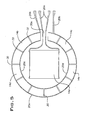
- Fig. 2 shows a schematic top view of a range cook top having a porcelain-enameled steel substrate according to the invention;
- Fig. 3 shows a schematic diagram of the electrical layout of a single heater according to one aspect of the invention;
- Fig. 4 shows a schematic diagram of the electrical layout of a single heater having temperature sensing according to the invention;
- Fig. 5 shows a schematic diagram of the electrical layout of a dual heater according to the invention; and
- Fig. 6 shows a schematic diagram of the electrical layout of a dual heater having temperature sensing according to the invention.
-
- Referring to Fig. 1, a heating apparatus, such a
range cook top 10, includes a generally horizontal planar surface forming asubstrate 12. A heating zone is formed on thesubstrate 12 and includes aresistive film layer 14 deposited on the substrate. Adielectric layer 16 can be disposed between theresistive film layer 14 and thesubstrate 12. A sealinglayer 18 can be disposed over theresistive film 14. Fig. 1 is schematic and the relative thicknesses of the layers do not represent actual thicknesses. The components described above are described in more detail below and in U.S. Patent Application Ser. No. 08/800,738. - The
substrate 12 is preferably a thermal shock resistant, rigid, and planar structure having a low electrical conductivity. In some applications, the substrate is suitable for supporting objects to be heated. In a domestic range cook top application, for example, thesubstrate 12 is supported by a frame of the range and forms the base of the cook top. Thesubstrate 12 can be glass ceramic, such as Li2Al2Si2O6 beta-quartz (LAS), available from Eurokera or Schott. For example, LAS glass ceramic or Si3N4 ceramic about 4.0 mm thick can be used in some cases. Also suitable is porcelain enameled (P-E) steel about 2.5 mm thick, that is, 2.0 mm ofsteel 12a with about 0.25 mm ofporcelain enamel 12b on each side. Examples of materials suitable for use as thesubstrate 12 include, but are not limited to, porcelainized carbon steel, porcelainized ferritic stainless steel, aluminum oxide, glass ceramic commonly referred to as Ceran, Si3N4-ceramic, and combinations of the foregoing. - The
resistive film 14 is preferably a thin film of atmospheric chemical vapor deposition (ACVD) applied F-doped or Sb-doped SnO2 able to withstand a power density of 1.5 to 14 W/cm2 and a current density between 11,000 and 90,000 A/cm2. A preferred dopant for tin dioxide is 0.1 to 0.5 weight percent fluorine. The film has a surface resistance of 75 Ohms per square. A voltage applied across the film causes a current to flow through the film thereby heating the film. Preferably, the thin film has a positive temperature coefficient (PTC) to prevent thermal run away. Other materials having the desired properties may also be suitable, such as a cermet-based thick film material, a polymer-based thick film material, or any type of electrically resistive film or coating. Because its resistance varies as a function of temperature, the resistive film can also be used as a temperature sensor. Alternatively, a separate temperature sensor can be located at the heating zone for closed loop temperature control. - One layer of the
porcelain enamel 12b acts as a dielectric layer. When the substrate is glass ceramic, thedielectric layer 16 is preferably a sol gel applied SiO2/Al2O3 or a screen printed and fired glass layer. The dielectric layer preferably insulates the substrate from currents flowing in theresistive film 14 and has a dielectric constant of about 5 to 8 (at room temperature and 50-60Hz). The dielectric constant should be as low and as stable as possible over the operating temperature range of the heater, which is about 20°C to 500°C. The dielectric layer should not substantially limit heat conduction from the resistive film to the substrate. Other materials having the desired properties may also be suitable. Examples of such materials include titanium dioxide, inorganic high temperature cements, sealing glasses, sol gel applied ceramics such as zirconia applied as a sol gel, high temperature paint, plasma or flame sprayed ceramics, or combinations thereof. The dielectric material selected preferably has a coefficient of thermal expansion as close to thesubstrate 12 as possible. A specific example of a preferred material for the dielectric layer is a glass layer fused to a glass ceramic substrate. Such fusing can be performed at temperatures in the range of 600°C to 850°C. This can be applied via atmospheric chemical vapor deposition. A further specific example of a preferred material for the dielectric layer is a ceramic material, for instance an alumina-based ceramic material, that is plasma sprayed or HVOF sprayed. - The
sealing layer 18 is a heat resistant, rigid material having high electrical insulating properties and high heat conductivity. The sealing layer resists corrosion of the resistive layer. Preferably, ACVD applied SiO2 is used. - Electrically conductive bus bars 20, such as cermet based silver thick film, are disposed on the
resistive film layer 14 and preferably covered by thesealing layer 18. The thickness of eachelectrode 20 is from about 5 to about 25 micrometers. The bus bars are preferably about 1.5 mm wide. The bus bars 20 are connected to a power supply for providing a controlled current or voltage to theresistive film 14. The bus bar configurations and connections are discussed below. - Referring to Fig. 2, the
cook top 10 includesseveral heating zones 22. Eachheating zone 22 includes resistive film and bus bars disposed on the substrate as discussed above. Preferably, theheating zones 22 are circular and correspond in size with conventional large and small cook top element sizes, for example, about 235 mm and 160 mm in diameter. When a P-E steel substrate is used, theheating zone 22 is separated from the remaining area of thecook top 10 by acircumferential slot 24. Theslot 24 thermally insulates the cook top 10 from theheating zone 22. The resistive film does not extend past the slot. Theslot 24 is discontinuous, interrupted by circumferentially spacedtongues 25. The tongues provide mechanical support for the heating zone and can provide a path for running electrical connections, such as conductive bus bar layers. The electrical connections are connected to a power source through a controller. Preferably, thetongues 25 are formed by leaving substrate material when theslot 24 is formed. Thus, the tongues have the same thickness as the substrate, but do not have porcelain enamel applied thereto expect where a path is provided for electrical conductors, wherein the enamel provides electrical insulation between the substrate and electrical conductors. One of thetongues 25a extends directly across the slot to serve as a bridge for simple routing of the bus bars. Theother tongues 25 follow a serpentine path across the slot. The serpentine tongues allow for thermal expansion of the cook top elements. The width and number of tongues are selected to provide support for the physical loads placed on the heating zone. Alternatively, thetongues 25 can be separate parts, such as insulating fasteners, added to secure the heating zone to the cook top. Inserts and sealers are provided in the slots. These are described in more detail in U.S. Patent Application Ser. No. 09/067,135. When a glass ceramic substrate is used, the slots are not necessary and the substrate can be formed as a continuous sheet. - Referring to Fig. 3, the arrangement of the bus bars and resistive layer are shown as they would appear from the bottom of the cook top with the bus bars being applied on the resistive layer. The
resistive layer 14 is applied as a nearly square rectangular element surrounded by an annular element formed by eight arcuate segments. Therectangular element 14a is approximately 80 mm by 85 mm. The arcuate segments have an outer radius of about 74 mm and an inner radius of about 60.5 mm. The segments are generally symmetrically spaced around therectangular element 14a.Gaps 30 between the segments are 4 mm wide at the corners of the rectangle and 2 mm wide at the major axes of the rectangle. A 15mm gap 30c is provided between two of the segments to provide a passage formain bus bars 20a. The gaps provide electrical insulation between different elements of the resistive layer. Gap width and location can be modified to alter the electrical and heating characteristics. For example, locatinggaps 30a at 43° from the vertical axis provides relatively even heating. Also, the maximum power density can be reduced from 13.5 W/cm2 to 12.6 W/cm2 by makinggaps 30b 2 mm wide instead of 4 mm wide. - The resistive layer elements and conductive elements are electrically insulated from each other by the
gaps 30. When a sealing layer (18 in Fig. 1) is provided, the sealant can fill the gaps to provide additional insulation. - The
main bus bars 20a are connected to respective legs to a power source, such as a two-phase power system providing a nominal 240 volts AC. The main bus bars are spaced 8 mm apart in thegap 30c, and include terminals connected to leads from the power source. Themain bus bars 20a supply power to the bus bars applied on the resistive layer elements. Fig. 3 shows a single heater in that all of the elements of the resistive layer are supplied from the same main bus bars. The terminals are spaced about 30 to 300mm from the heating zone to reduce the effects of heat on the connections. For example, the bus bars are run along one of the tongues (25a, Fig. 2) supporting the heating zone so that the terminals are located on a cooler part or edge of the cook top. - The bus bars extend along the inner edge of the first
arcuate segment 14b and the eightharcuate segment 14c. These bus bars 20a continue and extend along opposite edges of therectangular element 14a. Thearcuate segments 14 are connected bybus bars 20 extending along outer and inner edges of pairs of the arcuate segments. For example, abus bar 20b extends along the outer edges of the first and secondarcuate segments bus bar 20c extends along the inner edge of the second and thirdarcuate segments main bus bars 20a and ending at the othermain bus bar 20a. Thus, the rectangular element is connected in parallel with the arcuate segments. This arrangement provides about 1140W at 240VAC. - Referring to Fig. 4, the heater includes substantially the same configuration of
resistive layer elements 14 andbus bars 20 as shown in Fig. 3. That is, theresistive layer 14 is applied as a nearly square rectangular element surrounded by an annular element formed by eight arcuate segments. Therectangular element 14a, however, is divided into two separate rectangular elements by a 5mm gap 38. Thearcuate segments 14 are connected bybus bars 20 extending along outer and inner edges of pairs of the arcuate segments. Themain bus bars 20a are connected to respective legs of a two-phase power system providing a nominal 240 volts AC. - Temperature sensing circuits are added to monitor and control the temperature of the resistive layer elements. Conductive material 34, such as silver, and resistive material 36, such as tin oxide can be used as leads to a temperature sensor of the controller. The leads are applied similarly to the resistive and bus bar layers.
- One sensor is formed by a temperature control
resistive lead 36a running to the center of the rectangularresistive element 14a. Theresistive lead 36a is 1 mm wide and runs in thegap 38 extending through therectangular element 14a. A temperature controlconductive lead 34a runs through thegap 38 in the rectangularresistive element 14a and connects the two rectangular elements forming the nearly square rectangular element. Theconductive lead 34a is 5 mm wide across half of therectangular element 14a, until the conductive lead contacts theresistive lead 36a, where the conductive lead then splits into two parts, each of which is 1 mm wide and spaced 1 mm from opposite sides of theresistive lead 36a, running to the opposite edge of therectangular element 14a. The temperature controlconductive lead 34a andresistive lead 36a are connected to a temperature controller, such as a PID electronic control, that monitors the temperature of the heater and controls the power to the bus bars 20 to maintain a desired temperature. - Leads to a temperature limiting sensor are formed by a temperature limiting
resistive lead 36b following an arcuate path spaced about 3 mm from the outside edge of some of the annular resistive elementarcuate segments 14. Ends of theresistive lead 36b extend inwardly to connect to one of the bus bars 20 on theresistive layer 14. The temperature limiting resistive leads 36b are 4 mm wide. A temperature limitingconductive lead 34b is connected to one end of thebus bar 20b extending along the outer edges of the first and secondarcuate segments conductive lead 34b is 1.5 mm wide or wider. Thus, thebus bar 20b connected to theconductive lead 34b serves the dual purposes of conducting current between thearcuate segments resistive lead 36b is spaced from theconductive lead 34b andbus bar 20b, but connected to thebus bar 20b at or near opposite ends of thearcuate segments resistive lead 36b contacts thebus bar 20b only where the temperature is to be sensed. Leads to the temperature limiting sensor can be provided for other arcuate segments. An example is shown for the fifth andsixth segments - The temperature limiting
conductive lead 34b andresistive lead 36b are connected to the temperature controller, which monitors the temperature of the heater at the junctions of the conductive and resistive leads. If the temperature exceeds a specified maximum desired temperature, the controller overrides the control based on the signals from the temperature control sensors and reduces or cuts off power to the bus bars 20. - The temperature signals from the temperature sensing leads 34, 36 can be a small DC signal (in the millivolt range) the accuracy of which is not affected by the 240 VAC power supplied to the heater.
- Referring to Fig. 5, the
resistive layer 14 is applied as a nearly square rectangular element surrounded by an annular element formed by four arcuate segments. Therectangle 14a is approximately 80 mm by 85 mm. The arcuate segments have an outer radius of about 91.5 mm and an inner radius of about 66.5 mm. The segments are generally symmetrically spaced around therectangle 14a.Gaps 30 between the segments are 2 mm wide. Each of the four arcuate segments is divided into three subsegments by tworadial masking gaps 32, which are 2 mm wide. The maskinggaps 32 are necessary because of limitations on the masking method used to apply the resistive layer on the substrate. These maskinggaps 32 do not believed significantly affect the electrical or heating characteristics and therefore are not discussed further. A 21 mmmain gap 30a is provided between two of the segments to provide a passage for innermain bus bars 20a. Gap width and location can be modified to alter the electrical and heating characteristics. For example, the maximum power density can be reduced from 13.7 W/cm2 to 12.7 W/cm2 by making themain gap 30a 9 mm wide instead of 21 mm wide. - The inner
main bus bars 20a are connected to respective legs of a two-phase power system providing a nominal 240 volts AC. The inner main bus bars are spaced 8 mm apart in themain gap 30a. Outer main bus bars 20b are connected to respective legs of the two-phase power system that can be controlled separately. Themain bus bars main bus bars 20a supply power to the bus bars applied on the rectangular resistive layer element. The outer main bus bars 20b supply power to the bus bars applied on the annular resistive layer elements. - The inner
main bus bars 20a extend along opposite edges of therectangular element 14a. The innermain bus bars 20a are slightly wider at the corners of therectangular element 14a to facilitate the masking process. The outer main bus bars 20b extend along respective outer edges of the first and fourtharcuate segments arcuate segments 14 are connected bybus bars 20 extending along outer and inner edges of pairs of the arcuate segments so that the segments are connected in series. For example, abus bar 20c extends along the inner edges of the first and secondarcuate segments bus bar 20e extends along the outer edge of the second and thirdarcuate segments bus bar 20d extends along the inner edge of the third and fourtharcuate segments main bus bar 20b. This arrangement provides about 700W at 240VAC when power is supplied only to therectangular element 14a and about 1700 W at 240 VAC when power is supplied to all of the resistive elements. - Referring to Fig. 6, the heater includes substantially the same configuration of
resistive layer elements 14 andbus bars 20 as shown in Fig. 5. That is, theresistive layer 14 is applied as a nearly square rectangular element surrounded by an annular element formed by four arcuate segments. Therectangular element 14a, however, is divided into two separate rectangular elements by a 5mm gap 38. Thearcuate segments 14 are connected bybus bars 20 extending along outer and inner edges of pairs of the arcuate segments. Themain bus bars - Temperature sensing circuits similar to those shown in Fig. 4 are added to monitor and control the temperature of the resistive layer elements. Leads to the temperature sensor include a temperature control
resistive lead 36a running to the center of the rectangularresistive element 14a. Theresistive lead 36a is 1 mm wide and runs in thegap 38 in therectangular element 14a. A temperature controlconductive lead 34a runs through thegap 38 in the rectangularresistive element 14a and connects the two rectangular elements forming the nearly square rectangular element. Theconductive lead 34a can extend slightly past the edges of the two rectangular elements to ensure that the two rectangular elements do not contact each other; a small amount of resistive thin film connecting the two rectangular elements could cause localized overheating. Theconductive lead 34a is 5 mm wide across half of the rectangular element, until the conductive lead contacts theresistive lead 36a, where the conductive lead then splits into two parts, each of which is 1 mm wide and spaced 1 mm from opposite sides of theresistive lead 36a, running to the opposite edge of therectangular element 14a. The temperature controlconductive lead 34a andresistive lead 36a are connected to the temperature controller, which monitors the temperature of the heater and controls the power to the bus bars 20 to maintain a desired temperature. - Leads to the temperature sensor also include a temperature limiting
resistive lead 36b following an arcuate path spaced about 3 mm from the outside edge of some of the annular resistive elementarcuate segments 14a. Ends of theresistive lead 36b extend inwardly to connect to one of the bus bars 20 on theresistive layer 14. The temperature limiting resistive leads 36b are 4 mm wide. The outermain bus bar 20b extending along the outer edge of the firstarcuate segment 14b serves as an outer temperature limiting conductive lead. Thus, thebus bar 20b connected to theresistive lead 36b serves the dual purposes of supplying power to the firstarcuate segment 14b and providing a temperature sensing signal. Theresistive lead 36b is connected to thebus bar 20b at or near opposite ends of thearcuate segment 14b and contacts thebus bar 20b only where the temperature is to be sensed. A similar temperature limiting sensor can be provided for other arcuate segments. An example is shown for thethird segment 14e. Because there is no lead running to theouter bus bar 20e on thethird segment 14e, an outer temperature limitingconductive lead 34c is connected between the controller and thebus bar 20e. - A pair of inner temperature limiting
resistive leads 36c connects to the rectangularresistive element 14a near corners of the rectangular element. Temperature is sensed near the corners of the rectangular element. Thus, the innermain bus bars 20a serve the dual purposes of supplying power to therectangular element 14a and providing a temperature sensing signal. - The inner and outer
main bus bars conductive lead 34c, and inner and outer temperature limitingresistive leads - The present disclosure describes several embodiments of the invention, however, the invention is not limited to these embodiments. Other variations are contemplated to be within the spirit and scope of the invention and appended claims.
Claims (22)
- A heater comprising:a substrate having a heating zone;a resistive layer disposed on at least part of the substrate heating zone and forming an annular heating element divided into arcuate segments; andconductive bus bars electrically connecting the arcuate segments in series.
- A heater according to claim 1 wherein the bus bars are disposed on edges of the arcuate segments.
- A heater according to claim 1 wherein the bus bars are respectively connected along inner and outer edges of the arcuate segments.
- A heater according to claim 3 wherein a first one of the bus bars is connected along a first edge of a first one of the arcuate segments and a second one of the bus bars is connected along a second edge of the first arcuate segment opposite the first edge and along an edge of a second one of the arcuate segments.
- A heater according to claim 1 wherein the resistive layer includes first, second, third, and fourth of the arcuate segments, a first one of the bus bars is connected along an outer edge of the first segment, a second one of the bus bars is connected along inner edges of the first and second segments, a third one of the bus bars is connected along outer edges of the second and third segments, a fourth one of the bus bars is connected along inner edges of the third and fourth segments, and a fifth one of the bus bars is connected along an outer edge of the fourth segment.
- A heater according to claim 5 wherein the first and fifth bus bars are connected to a power source.
- A heater according to claim 1 wherein the resistive layer includes first, second, third, fourth, fifth, sixth, seventh, and eighth of the arcuate segments, a first one of the bus bars is connected along an inner edge of the first segment, a second one of the bus bars is connected along outer edges of the first and second segments, a third one of the bus bars is connected along inner edges of the second and third segments, a fourth one of the bus bars is connected along outer edges of the third and fourth segments, a fifth one of the bus bars is connected along inner edges of the fourth and fifth segments, a sixth one of the bus bars is connected along outer edges of the fifth and sixth segments, a seventh one of the bus bars is connected along inner edges of the sixth and seventh segments, an eighth one of the bus bars is connected along outer edges of the seventh and eighth segments, and a ninth one of the bus bars is connected along an inner edge of the eighth segment.
- A heater according to claim 7 wherein the first and ninth bus bars are connected to a power source.
- A heater according to claim 1 wherein the resistive layer further comprises a separate element disposed within the annular element and further comprising conductive bus bars disposed along opposite edges of the separate element.
- A heater according to claim 9 wherein the separate element bus bars are connected to the annular element bus bars so that the separate element is electrically connected in parallel with the annular element.
- A heater according to claim 9 wherein the separate element bus bars are arranged so that power to the separate element can be controlled separately from the annular element.
- A heater according to claim 1 further comprising a resistive temperature sensing lead connected from a conductive element disposed adjacent the resistive layer to a temperature sensor.
- A heater according to claim 12 wherein the conductive element is one of the bus bars.
- A heater according to claim 12 further comprising a conductive temperature sensing lead connected to the conductive element.
- A heater according to claim 14 wherein the temperature sensing leads are connected to a controller for monitoring the temperature of the heater where the conductive leads meet the resistive leads.
- A heater according to claim 12 wherein the conductive element is a conductive temperature sensing lead.
- A heater according to claim 1 wherein gaps between different segments of the resistant layer are filled with insulating material.
- A heater according to claim 1 further comprising a dielectric layer disposed between the resistive layer and the substrate.
- A heater comprising:a substrate having a heating zone;a resistive layer disposed on at least part of the substrate heating zone and forming an annular heating element divided into arcuate segments and a rectangular element disposed within the annular element;annular element conductive bus bars disposed on edges of the arcuate segments electrically connecting the arcuate segments in series, wherein a first one of the annular element bus bars is connected along a first edge of a first one of the arcuate segments and a second one of the annular element bus bars is connected along a second edge of the first arcuate segment opposite the first edge and along an edge of a second one of the arcuate segments, a last one of the annular element bus bars is connected along an edge of a last one of the arcuate segments in the series, and the first and last annular element bus bars are connected to a power source; andrectangular element conductive bus bars disposed along opposite edges of the rectangular element and connected to the power source.
- A heater according to claim 19 wherein the rectangular element bus bars are connected to the annular element bus bars so that the rectangular element is electrically connected in parallel with the annular element.
- A heater according to claim 19 wherein the rectangular element bus bars are arranged so that power to the rectangular element can be controlled separately from the annular element.
- A heater according to claim 19 further comprising a resistive temperature sensing lead connected to a conductive element disposed adjacent the resistive layer, wherein the temperature sensing leads are connected to a controller for monitoring the temperature of the heater.
Applications Claiming Priority (2)
| Application Number | Priority Date | Filing Date | Title |
|---|---|---|---|
| US09/451,733 US6225608B1 (en) | 1999-11-30 | 1999-11-30 | Circular film heater |
| US451733 | 1999-11-30 |
Publications (2)
| Publication Number | Publication Date |
|---|---|
| EP1107648A2 true EP1107648A2 (en) | 2001-06-13 |
| EP1107648A3 EP1107648A3 (en) | 2002-07-17 |
Family
ID=23793480
Family Applications (1)
| Application Number | Title | Priority Date | Filing Date |
|---|---|---|---|
| EP00850200A Withdrawn EP1107648A3 (en) | 1999-11-30 | 2000-11-29 | Circular film heater |
Country Status (2)
| Country | Link |
|---|---|
| US (1) | US6225608B1 (en) |
| EP (1) | EP1107648A3 (en) |
Cited By (5)
| Publication number | Priority date | Publication date | Assignee | Title |
|---|---|---|---|---|
| EP1519630A1 (en) * | 2003-09-26 | 2005-03-30 | Electrolux Home Products Corporation N.V. | Heater for cooking apparatus or the like |
| EP1696705A1 (en) | 2005-02-26 | 2006-08-30 | Electrolux Home Products Corporation N.V. | Flat heating element of small thickness, in particular for cooking oven |
| WO2018029002A1 (en) * | 2016-08-08 | 2018-02-15 | Arcelik Anonim Sirketi | Thin film heating cooker detecting cooking utensils with improved heating methods |
| WO2018029004A1 (en) * | 2016-08-08 | 2018-02-15 | Arcelik Anonim Sirketi | Thin film heating cooker heating element configuration |
| WO2018028999A1 (en) * | 2016-08-08 | 2018-02-15 | Arcelik Anonim Sirketi | Thin film heating cooker heating element adjustment for power efficiency |
Families Citing this family (22)
| Publication number | Priority date | Publication date | Assignee | Title |
|---|---|---|---|---|
| CN100493267C (en) * | 2000-11-29 | 2009-05-27 | 萨莫希雷梅克斯公司 | Resistive heaters and uses thereof |
| DE10225337A1 (en) * | 2002-06-06 | 2003-12-24 | Schott Glas | Cooking system with directly heated glass ceramic plate |
| FR2852478B1 (en) * | 2003-03-10 | 2006-07-07 | Alain Marec | IMPROVEMENT TO HEATING DEVICES OF THE HEAT BANDS TYPE. |
| CN1883229A (en) * | 2003-11-20 | 2006-12-20 | 皇家飞利浦电子股份有限公司 | Thin- film heating element |
| US7196295B2 (en) * | 2003-11-21 | 2007-03-27 | Watlow Electric Manufacturing Company | Two-wire layered heater system |
| US8680443B2 (en) * | 2004-01-06 | 2014-03-25 | Watlow Electric Manufacturing Company | Combined material layering technologies for electric heaters |
| WO2005101906A1 (en) * | 2004-03-18 | 2005-10-27 | Alain Marec | Improvement of heating devices embodied in the form of heating strips |
| US8890038B2 (en) | 2004-03-30 | 2014-11-18 | Thermoceramix Inc. | Heating apparatus with multiple element array |
| US7482556B2 (en) * | 2004-03-30 | 2009-01-27 | Shaw John R | Heating apparatus with multiple element array |
| US7126092B2 (en) * | 2005-01-13 | 2006-10-24 | Watlow Electric Manufacturing Company | Heater for wafer processing and methods of operating and manufacturing the same |
| US7834296B2 (en) | 2005-06-24 | 2010-11-16 | Thermoceramix Inc. | Electric grill and method of providing the same |
| TWM289949U (en) * | 2005-10-25 | 2006-04-21 | Syntran Co Ltd | Electrical heater structure |
| KR100877355B1 (en) * | 2007-12-14 | 2009-01-07 | 주식회사 에이엠오 | Heater for preventing freezing burst of pipe using heating element having strip type surface and fabricating method thereof |
| EP2290307B1 (en) * | 2008-04-28 | 2018-09-12 | Amogreentech Co., Ltd. | Evaporator with defrost heater having strip type plane heating elements |
| TWI381989B (en) * | 2009-03-27 | 2013-01-11 | Hon Hai Prec Ind Co Ltd | Heating device |
| US8689481B2 (en) * | 2011-12-12 | 2014-04-08 | Pab Two, Llc | Integration of surface heating to an enclosure |
| US10591167B2 (en) * | 2015-10-28 | 2020-03-17 | Haier Us Appliance Solutions, Inc. | Cooktop appliance control system |
| CN106555151A (en) * | 2016-11-23 | 2017-04-05 | 东莞珂洛赫慕电子材料科技有限公司 | A kind of plasma spraying aluminium base electrothermal device and preparation method thereof |
| CN106676457A (en) * | 2016-11-23 | 2017-05-17 | 东莞珂洛赫慕电子材料科技有限公司 | Preparation method for plasma spraying electric heating device dielectric layer |
| DE102016224069A1 (en) * | 2016-12-02 | 2018-06-07 | E.G.O. Elektro-Gerätebau GmbH | Cooking utensil with a cooking plate and a heater underneath |
| US11562913B2 (en) * | 2019-04-25 | 2023-01-24 | Watlow Electric Manufacturing Company | Multi-zone azimuthal heater |
| US11828796B1 (en) | 2023-05-02 | 2023-11-28 | AEM Holdings Ltd. | Integrated heater and temperature measurement |
Citations (2)
| Publication number | Priority date | Publication date | Assignee | Title |
|---|---|---|---|---|
| US4233497A (en) * | 1978-12-04 | 1980-11-11 | Lowell Herman H | Electric heating element |
| EP0954201A2 (en) * | 1998-04-27 | 1999-11-03 | White Consolidated Industries, Inc. | Circular film heater and porcelain enamel cooktop |
Family Cites Families (23)
| Publication number | Priority date | Publication date | Assignee | Title |
|---|---|---|---|---|
| US851440A (en) | 1906-06-11 | 1907-04-23 | Edward George Rivers | Electrical heating element or resistance. |
| US1352934A (en) | 1919-10-17 | 1920-09-14 | Elek Sk Varmeteknik As | Electric-heating body |
| US2026797A (en) | 1934-03-01 | 1936-01-07 | Standard Electric Stove Compan | Inclosed heating element for electric stoves |
| US3167638A (en) | 1961-03-22 | 1965-01-26 | Gen Motors Corp | Surface cooking unit |
| US3694627A (en) | 1970-12-23 | 1972-09-26 | Whirlpool Co | Heating element & method of making |
| US3895216A (en) | 1974-09-30 | 1975-07-15 | Gen Electric | Low thermal mass solid plate surface heating unit |
| US4002883A (en) | 1975-07-23 | 1977-01-11 | General Electric Company | Glass-ceramic plate with multiple coil film heaters |
| US4384192A (en) | 1981-03-02 | 1983-05-17 | Teledyne Still-Man Manufacturing | Electric heating element |
| US4508961A (en) | 1982-03-02 | 1985-04-02 | Micropore International Limited | Electric radiant heater units for glass ceramic top cookers |
| DE3315438A1 (en) | 1983-04-28 | 1984-10-31 | E.G.O. Elektro-Geräte Blanc u. Fischer, 7519 Oberderdingen | HEATING ELEMENT FOR HEATING COOKING, HEATING PLATES OR THE LIKE |
| FR2580887B1 (en) | 1985-04-19 | 1989-04-14 | Seb Sa | ELECTRIC RESISTANCE FLAT HEATING ELEMENT AND HEATING ARTICLE COMPRISING SUCH AN ELEMENT |
| DE3545442A1 (en) | 1985-12-20 | 1987-06-25 | Bosch Siemens Hausgeraete | HEATING ELEMENT FOR THERMAL HOME APPLIANCES, ESPECIALLY FOR COOKING POINTS |
| FR2623684A1 (en) | 1987-11-24 | 1989-05-26 | Labo Electronique Physique | VITROCERAMIC HEATING ELEMENT |
| IT1218221B (en) | 1988-04-15 | 1990-04-12 | Bayer Ag | HIGH TEMPERATURE HEATING SYSTEMS AND METHOD TO PRODUCE THEM |
| EP0360884A1 (en) | 1988-09-26 | 1990-04-04 | Siemens Aktiengesellschaft | CMOS differential comparator with offset voltage |
| DE3907029A1 (en) | 1989-03-04 | 1990-09-06 | Ego Elektro Blanc & Fischer | ELECTRIC COOKING PLATE |
| US5019691A (en) | 1990-07-11 | 1991-05-28 | Fute Lai | Heating device |
| DE4022846C2 (en) | 1990-07-18 | 1994-08-11 | Schott Glaswerke | Device for power control and limitation in a heating surface made of glass ceramic or a comparable material |
| GB2263379B (en) | 1992-01-10 | 1995-07-26 | Ceramaspeed Ltd | Radiant heater having multiple heating zones |
| JPH05326112A (en) | 1992-05-21 | 1993-12-10 | Shin Etsu Chem Co Ltd | Layered ceramic heater |
| GB2275160B (en) | 1993-02-11 | 1996-04-03 | Ceramaspeed Ltd | Method of manufacturing a radiant electric heater |
| GB2275163B (en) | 1993-02-11 | 1996-04-03 | Ceramaspeed Ltd | Radiant electric heater and method |
| US5616266A (en) | 1994-07-29 | 1997-04-01 | Thermal Dynamics U.S.A. Ltd. Co. | Resistance heating element with large area, thin film and method |
-
1999
- 1999-11-30 US US09/451,733 patent/US6225608B1/en not_active Expired - Lifetime
-
2000
- 2000-11-29 EP EP00850200A patent/EP1107648A3/en not_active Withdrawn
Patent Citations (2)
| Publication number | Priority date | Publication date | Assignee | Title |
|---|---|---|---|---|
| US4233497A (en) * | 1978-12-04 | 1980-11-11 | Lowell Herman H | Electric heating element |
| EP0954201A2 (en) * | 1998-04-27 | 1999-11-03 | White Consolidated Industries, Inc. | Circular film heater and porcelain enamel cooktop |
Cited By (6)
| Publication number | Priority date | Publication date | Assignee | Title |
|---|---|---|---|---|
| EP1519630A1 (en) * | 2003-09-26 | 2005-03-30 | Electrolux Home Products Corporation N.V. | Heater for cooking apparatus or the like |
| EP1696705A1 (en) | 2005-02-26 | 2006-08-30 | Electrolux Home Products Corporation N.V. | Flat heating element of small thickness, in particular for cooking oven |
| DE102005008903A1 (en) * | 2005-02-26 | 2006-08-31 | Electrolux Home Products Corporation N.V. | Large-area heating element of small thickness, in particular Garofenheizelement |
| WO2018029002A1 (en) * | 2016-08-08 | 2018-02-15 | Arcelik Anonim Sirketi | Thin film heating cooker detecting cooking utensils with improved heating methods |
| WO2018029004A1 (en) * | 2016-08-08 | 2018-02-15 | Arcelik Anonim Sirketi | Thin film heating cooker heating element configuration |
| WO2018028999A1 (en) * | 2016-08-08 | 2018-02-15 | Arcelik Anonim Sirketi | Thin film heating cooker heating element adjustment for power efficiency |
Also Published As
| Publication number | Publication date |
|---|---|
| EP1107648A3 (en) | 2002-07-17 |
| US6225608B1 (en) | 2001-05-01 |
Similar Documents
| Publication | Publication Date | Title |
|---|---|---|
| US6225608B1 (en) | Circular film heater | |
| EP0954201B1 (en) | Circular film heater and porcelain enamel cooktop | |
| FI87964B (en) | UPPVAERMNINGSELEMENT OCH UPPVAERMNINGSENHET | |
| CA1299631C (en) | Thick film electrically resistive tracks | |
| US5352864A (en) | Process and device for output control and limitation in a heating surface made from glass ceramic or a comparable material | |
| EP2186380B1 (en) | Electric heater | |
| US11253100B2 (en) | Electric heater and electric heating apparatus having same | |
| US11867410B2 (en) | Electric heater and cooking appliance having same | |
| US20230266015A1 (en) | Electric Heater And Cooking Appliance Having Same | |
| KR102159802B1 (en) | Electric Heater | |
| US20220357042A1 (en) | Electric heater and cooking appliance having same | |
| JPH03176987A (en) | Radiation electric heater | |
| US11602016B2 (en) | Electric heater and electric heating apparatus having same | |
| JPWO2019083045A1 (en) | Heater and heater system | |
| JPH07282961A (en) | Heater | |
| US7041942B2 (en) | Heating plate assembly for a cooking appliance | |
| Tait et al. | Thick film heater elements and temperature sensors in modern domestic appliances | |
| CA2282327A1 (en) | Heating element for a water-bed | |
| WO1997021326A1 (en) | A resistive heating element for a cooker | |
| WO2000065877A1 (en) | Safe thin film heater | |
| JPH0794264A (en) | Electromagnetic induction heating device | |
| MXPA06007799A (en) | Tailored heat transfer layered heater system | |
| JPH06151043A (en) | Ceramic sheet shape resistance heat generation element |
Legal Events
| Date | Code | Title | Description |
|---|---|---|---|
| PUAI | Public reference made under article 153(3) epc to a published international application that has entered the european phase |
Free format text: ORIGINAL CODE: 0009012 |
|
| AK | Designated contracting states |
Kind code of ref document: A2 Designated state(s): AT BE CH CY DE DK ES FI FR GB GR IE IT LI LU MC NL PT SE TR |
|
| AX | Request for extension of the european patent |
Free format text: AL;LT;LV;MK;RO;SI |
|
| PUAL | Search report despatched |
Free format text: ORIGINAL CODE: 0009013 |
|
| AK | Designated contracting states |
Kind code of ref document: A3 Designated state(s): AT BE CH CY DE DK ES FI FR GB GR IE IT LI LU MC NL PT SE TR |
|
| AX | Request for extension of the european patent |
Free format text: AL;LT;LV;MK;RO;SI |
|
| 17P | Request for examination filed |
Effective date: 20021213 |
|
| AKX | Designation fees paid |
Designated state(s): AT BE CH CY DE DK ES FI FR GB GR IE IT LI LU MC NL PT SE TR |
|
| STAA | Information on the status of an ep patent application or granted ep patent |
Free format text: STATUS: THE APPLICATION HAS BEEN WITHDRAWN |
|
| 18W | Application withdrawn |
Effective date: 20041021 |