EP1107563A2 - Light emitting display on a portable communication device for incoming phone calls - Google Patents
Light emitting display on a portable communication device for incoming phone calls Download PDFInfo
- Publication number
- EP1107563A2 EP1107563A2 EP00125020A EP00125020A EP1107563A2 EP 1107563 A2 EP1107563 A2 EP 1107563A2 EP 00125020 A EP00125020 A EP 00125020A EP 00125020 A EP00125020 A EP 00125020A EP 1107563 A2 EP1107563 A2 EP 1107563A2
- Authority
- EP
- European Patent Office
- Prior art keywords
- light emitting
- mobile phone
- emitting display
- communication device
- phone calls
- Prior art date
- Legal status (The legal status is an assumption and is not a legal conclusion. Google has not performed a legal analysis and makes no representation as to the accuracy of the status listed.)
- Withdrawn
Links
Images

Classifications
-
- H—ELECTRICITY
- H04—ELECTRIC COMMUNICATION TECHNIQUE
- H04M—TELEPHONIC COMMUNICATION
- H04M19/00—Current supply arrangements for telephone systems
- H04M19/02—Current supply arrangements for telephone systems providing ringing current or supervisory tones, e.g. dialling tone or busy tone
- H04M19/04—Current supply arrangements for telephone systems providing ringing current or supervisory tones, e.g. dialling tone or busy tone the ringing-current being generated at the substations
-
- H—ELECTRICITY
- H04—ELECTRIC COMMUNICATION TECHNIQUE
- H04B—TRANSMISSION
- H04B1/00—Details of transmission systems, not covered by a single one of groups H04B3/00 - H04B13/00; Details of transmission systems not characterised by the medium used for transmission
- H04B1/38—Transceivers, i.e. devices in which transmitter and receiver form a structural unit and in which at least one part is used for functions of transmitting and receiving
-
- H—ELECTRICITY
- H04—ELECTRIC COMMUNICATION TECHNIQUE
- H04M—TELEPHONIC COMMUNICATION
- H04M19/00—Current supply arrangements for telephone systems
- H04M19/02—Current supply arrangements for telephone systems providing ringing current or supervisory tones, e.g. dialling tone or busy tone
- H04M19/04—Current supply arrangements for telephone systems providing ringing current or supervisory tones, e.g. dialling tone or busy tone the ringing-current being generated at the substations
- H04M19/048—Arrangements providing optical indication of the incoming call, e.g. flasher circuits
Definitions
- the present invention relates to a light emitting display on a portable communication device for incoming phone calls.
- the present invention relates to a display with electro luminescent lamp on a cellular phone and on related attachment thereof to signal incoming phone calls.
- a communication device usually provides a screen to display signals of incoming phone calls.
- the screen on the communication device has an outer surface of light emitter only with a plain color.
- the outer surface on the screen is provided with a color same as the casing of the communication device, however the color can not be changed and are easy to become worn out.
- a primary object of the present invention is to provide a light emitting display on a communication device for incoming phone calls, which is made of electro luminescent lamp to generate various bright movable figures and remind the user in case of the communication device receiving incoming communication signals.
- Another object of the present invention is to provide a light emitting display on a communication device for incoming phone calls, which offers the communication device a new dynamic appearance.
- a further Object of the present invention is to provide a light emitting display on a communication device for incoming phone calls, which may be made to be independent of the communication device itself.
- a light emitting display on a portable communication device such as a cellular phone for incoming phone calls comprises an electro luminescent lamp 51 and a control circuit.
- the electro luminescent lamp 51 is mounted on a battery 6 of the portable communication device and connects with the control circuit.
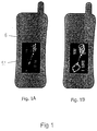
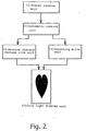
- the control circuit further comprises a signal receive unit 1, an automatic control unit 2, a voltage reversed rising unit 3, and a switching driver unit 4 and these units are connected to the luminescent lamp display unit 5 sequentially. Therefore, the luminescent lamp 51 attached to the communication device can generate various movable figures based on above said arrangement to remind the user while a communication signal is received. Meanwhile, the display of movable figures offers a personalized outer casing on the communication device. It can be seen that Fig. 1A shows the light emitting display of the present invention is in a state of not receiving any phone call and Fig. 1B is in a state of having received a phone call.
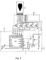
- the RF signal when a RF signal is emitted by the mobile phone and sensed by DVN, the RF signal is triggered by a VN terminal of IC1 and filtered in the IC1 to generate a trigger signal after being regulated.
- the trigger signal controls an internal oscillation circuit to send out a flash signal and an internal timer circuit is started. Once a preset value of time duration is reached, the flash is ceased and each part of the circuit is shut down at the same time. In this way, the circuit is in a state of waiting with low power consumption.
- the flash signal sent out by the internal oscillation circuit passes through L1-L5 in a respective way A, B, C, D, and E shown in Fig.
- D1-D5 are started at each electro luminescent flash stage and the voltage rise circuit 3 with frequency change, i.e., the point F has voltage at the time of L1-L5 being in a state of flash.
- R6, R7, C3, C4, Q6, and TR1 consist in an oscillation driving circuit and the oscillation driving circuit begins to oscillate for sending out the voltage required by the electro luminescent lamp while point F receives a control signal.
- the wave of voltage at point F is shown in Fig. 4B and point F is an impulse wave to decrease the current at the time of driving.
- the voltage at point F is a control voltage for direct current as shown in Fig. 4C such that it may result in an increased current in the circuit under load. Under the same driving load, the working current needed in case of Fig. 4B may save 10mA ⁇ 20mA.
Landscapes
- Engineering & Computer Science (AREA)
- Signal Processing (AREA)
- Computer Networks & Wireless Communication (AREA)
- Telephone Function (AREA)
- Telephone Set Structure (AREA)
- Mobile Radio Communication Systems (AREA)
- Transceivers (AREA)
Abstract
Description
Claims (4)
- A light emitting display on a mobile phone for incoming phone calls, comprisingan electro luminescent lamp, being provided on the mobile phone;a control circuit, being provided in the mobile phone; anda battery, being provided in the mobile phone either.
- The light emitting display on a mobile phone and for incoming phone calls as defined in claim 1, wherein the electro luminescent lamp is mounted on the battery.
- The light emitting display on a mobile phone for incoming phone calls as defined in claim 1, wherein the control circuit is set on the battery and further comprises a signal receive unit, an automatic control unit, a reverse changed voltage rising unit, switching drive unit, and an electro luminescent lamp display unit.
- The light emitting display on a mobile phone for incoming phone calls as defined in claim 1, wherein the cold light plate connects with the control circuit and with the battery respectively to use the same power supply as the mobile phone itself.
Applications Claiming Priority (2)
| Application Number | Priority Date | Filing Date | Title |
|---|---|---|---|
| CN99240943U CN2414561Y (en) | 1999-12-06 | 1999-12-06 | Cool light chip calling-number indicator for mobile telephone and the like teleccommunication equipment |
| CN99240943 | 1999-12-06 |
Publications (2)
| Publication Number | Publication Date |
|---|---|
| EP1107563A2 true EP1107563A2 (en) | 2001-06-13 |
| EP1107563A3 EP1107563A3 (en) | 2002-09-25 |
Family
ID=5316908
Family Applications (1)
| Application Number | Title | Priority Date | Filing Date |
|---|---|---|---|
| EP00125020A Withdrawn EP1107563A3 (en) | 1999-12-06 | 2000-11-16 | Light emitting display on a portable communication device for incoming phone calls |
Country Status (5)
| Country | Link |
|---|---|
| EP (1) | EP1107563A3 (en) |
| JP (1) | JP3077603U (en) |
| KR (1) | KR200233254Y1 (en) |
| CN (1) | CN2414561Y (en) |
| CA (1) | CA2325673A1 (en) |
Cited By (1)
| Publication number | Priority date | Publication date | Assignee | Title |
|---|---|---|---|---|
| CN106550137A (en) * | 2016-10-26 | 2017-03-29 | 上海传英信息技术有限公司 | A kind of breath light points out the method and device of battery electric quantity |
Family Cites Families (6)
| Publication number | Priority date | Publication date | Assignee | Title |
|---|---|---|---|---|
| JPH11500588A (en) * | 1995-01-31 | 1999-01-12 | モトローラ・インコーポレイテッド | Selective paging receiver in battery of two-way communication device |
| SG67393A1 (en) * | 1996-07-01 | 1999-09-21 | Motorola Inc | Portable power source with visual image display |
| FI103238B1 (en) * | 1997-02-21 | 1999-05-14 | Nokia Mobile Phones Ltd | Mobile communication devices |
| US6125286A (en) * | 1997-06-05 | 2000-09-26 | Motorola, Inc. | Communication device having multiple displays and method of operating the same |
| KR19990047842A (en) * | 1997-12-05 | 1999-07-05 | 윤종용 | Antenna device of portable terminal |
| JP3105880B2 (en) * | 1999-01-28 | 2000-11-06 | 埼玉日本電気株式会社 | Mobile phone |
-
1999
- 1999-12-06 CN CN99240943U patent/CN2414561Y/en not_active Expired - Fee Related
-
2000
- 2000-11-09 JP JP2000008016U patent/JP3077603U/en not_active Expired - Fee Related
- 2000-11-10 CA CA002325673A patent/CA2325673A1/en not_active Abandoned
- 2000-11-16 EP EP00125020A patent/EP1107563A3/en not_active Withdrawn
- 2000-11-18 KR KR2020000032629U patent/KR200233254Y1/en not_active Expired - Fee Related
Cited By (1)
| Publication number | Priority date | Publication date | Assignee | Title |
|---|---|---|---|---|
| CN106550137A (en) * | 2016-10-26 | 2017-03-29 | 上海传英信息技术有限公司 | A kind of breath light points out the method and device of battery electric quantity |
Also Published As
| Publication number | Publication date |
|---|---|
| JP3077603U (en) | 2001-05-29 |
| CN2414561Y (en) | 2001-01-10 |
| CA2325673A1 (en) | 2001-06-06 |
| EP1107563A3 (en) | 2002-09-25 |
| KR200233254Y1 (en) | 2001-09-26 |
Similar Documents
| Publication | Publication Date | Title |
|---|---|---|
| US6094565A (en) | Closeable communication device and method of operating the same | |
| US6320330B1 (en) | Illuminating electronic device and illumination method | |
| JP2004519936A (en) | System and method for backlight control in a wireless communication device | |
| JPH0677875A (en) | Charging stand for cordless telephone handsets | |
| JPH10215302A (en) | Mobile phone | |
| CA2325673A1 (en) | Light emitting display on a portable communication device for incoming phone calls | |
| JP2000224287A (en) | Mobile phone | |
| GB2308939A (en) | Keypad illumination circuit for a portable telephone | |
| US6397085B1 (en) | Telephone with key-click sound volume control | |
| KR200191207Y1 (en) | an apparatus for displaying the receiving signal of cellular phone | |
| JPH09224000A (en) | Portable wireless communication device | |
| JP3568472B2 (en) | mobile phone | |
| KR920011069B1 (en) | How to turn on keypad when dialing in cordless phone | |
| JPH0595395A (en) | Mobile phone | |
| KR200186722Y1 (en) | Circuit structure of radiaton-accessory for portable-phone | |
| JPH0453076Y2 (en) | ||
| KR200164910Y1 (en) | Portable telephone with flashlight | |
| KR200241000Y1 (en) | Apparatus for indicating ring signal of handphone | |
| KR100356200B1 (en) | Display device of calling for hand-phone | |
| KR200172528Y1 (en) | Display device of calling for hand-phone | |
| JP2002077378A (en) | Mobile phone | |
| CN2354274Y (en) | multifunctional laser pointer | |
| KR200172068Y1 (en) | Portablephone band with displaying ringback signal | |
| JPH09261753A (en) | Mobile phone | |
| KR100260949B1 (en) | How to temporarily stop a telephone call and its ring tone |
Legal Events
| Date | Code | Title | Description |
|---|---|---|---|
| PUAI | Public reference made under article 153(3) epc to a published international application that has entered the european phase |
Free format text: ORIGINAL CODE: 0009012 |
|
| AK | Designated contracting states |
Kind code of ref document: A2 Designated state(s): AT BE CH CY DE DK ES FI FR GB GR IE IT LI LU MC NL PT SE TR |
|
| AX | Request for extension of the european patent |
Free format text: AL;LT;LV;MK;RO;SI |
|
| 17P | Request for examination filed |
Effective date: 20011204 |
|
| PUAL | Search report despatched |
Free format text: ORIGINAL CODE: 0009013 |
|
| AK | Designated contracting states |
Kind code of ref document: A3 Designated state(s): AT BE CH CY DE DK ES FI FR GB GR IE IT LI LU MC NL PT SE TR |
|
| AX | Request for extension of the european patent |
Free format text: AL;LT;LV;MK;RO;SI |
|
| RIC1 | Information provided on ipc code assigned before grant |
Free format text: 7H 04M 1/725 A, 7H 04M 1/02 B |
|
| AKX | Designation fees paid | ||
| REG | Reference to a national code |
Ref country code: DE Ref legal event code: 8566 |
|
| STAA | Information on the status of an ep patent application or granted ep patent |
Free format text: STATUS: THE APPLICATION IS DEEMED TO BE WITHDRAWN |
|
| 18D | Application deemed to be withdrawn |
Effective date: 20030603 |