FIELD OF THE INVENTION
The present invention relates to a system
interconnect power converter interconnected to a
commercial power system (to be referred to as a "system"
hereinafter) and a power generation apparatus using the
same and, more particularly, to a power converter of
insulated-transformerless type used in a power generation
apparatus which comprises a direct current power supply
such as a solar battery having a large ground capacitor and
is interconnected to a low-voltage distribution system
having one grounded line, and a power generation apparatus
using the same.
BACKGROUND OF THE INVENTION
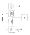
Fig. 2 is a block diagram showing the arrangement of
a solar power generation apparatus interconnected to a
low-voltage distribution system.
A solar battery array 1 is constituted by combining
a plurality of solar battery modules serially/parallelly
so as to obtain a desired output voltage and current.
Direct current power output from the solar battery array
1 is input to a system interconnect power converter 2 (to
be referred to as a "power conditioner" hereinafter) where
the direct current power is converted into alternate
current power. The output of the power conditioner 2 is
connected to a low-voltage distribution system 4 via a
customer's ground fault interrupter 3. A load 5 is
connected between the power conditioner 2 and the
customer's ground fault interrupter 3. Wiring inside the
customer's premises is wiring from the customer's ground
fault interrupter 3 to the power conditioner 2 and load 5.
The customer's ground fault interrupter 3 detects a ground
fault current to detect an electrical leakage inside the
customer's premises, and interrupts the connection between
the customer's equipment and the low-voltage distribution
system 4 so as not to influence the low-voltage distribution
system 4 outside the customer's premises.
The solar battery array 1 has a ground capacitor 6.
As a solar battery module constituting the solar battery
array 1, built-in modules and low-profile modules have
recently been developed. In some cases, a conductive
member (metal plate or the like) as a reinforcing member
or a conductive member such as a metal plate as a base member
covers a roof. In this case, a solar battery cell and metal
plate face each other at a small interval with a large area,
which increases the ground capacitor 6. If water attaches
to the surface and any area of a solar battery module owing
to rain or the like, the ground capacitor 6 is ocurred by
the water.
On the other hand, most of the system interconnect
power conditioners 2 recently adopt a so-called
transformerless method having no insulated transformer in
order to attain high efficiency, small size, light weight,
and low cost.
The present inventors have found that when the ground
capacitor 6 is large, the system interconnect power
conditioner 2 is of transformerless type, and a ground fault
occurs outside the customer's premises, the ground fault
current flows through the ground capacitor 6 of the solar
battery array 1 and the power conditioner 2 to cause
unwanted interruption operation in the customer's ground
fault interrupter 3. This unwanted interruption operation
generated in the customer's ground fault interrupter 3
causes a power failure inside the customer's premises
though no electrical leakage occurs inside the customer's
premises.
This problem is not limited to the solar power
generation system. The same problem arises in a power
generation system using a fuel cell if the ground capacitor
is large. A ground fault outside the customer's premises
causes the customer's ground fault interrupter 3 to
unnecessarily perform interruption operation, which may
generate a power failure inside the customer's premises.
SUMMARY OF THE INVENTION
The present invention has been made to overcome the
conventional drawbacks, and has as its object to prevent
unwanted interruption operation of a customer's ground
fault interrupter caused by a ground fault outside the
consumer.
To achieve the object, a preferred embodiment of the
present invention discloses a power converter for
converting direct current power to alternate current power
and supplying the alternate current power to a power system,
said power converter comprising: a converter for boosting
a voltage of direct current power supplied from a direct
current power supply having a ground capacitor; an inverter
for converting the direct current power supplied from said
converter into alternate current power, wherein an input
and output of said inverter are not insulated; a switch
which is connected to an output terminal of said inverter
and opens/closes an output of said power converter by a
mechanical contact; a detector for detecting a ground fault
within a shorter time than an operation time of a customer's
ground fault interrupter interposed between said power
converter and a power system having one grounded line; and
a controller for controlling operations of said converter,
said inverter, and said switch, wherein when said detector
detects a ground fault, said controller changes said switch
to an open state, blocks a gate of said inverter, and holds
an output voltage of said converter to be higher than a peak
value of an alternate current voltage of the power system
until at least said switch changes to the open state.
Another preferred embodiment of the present
invention discloses a power generation apparatus for
supplying alternate current power to a power system and
comprising a direct current power supply having a ground
capacitor, and a power converter for converting direct
current power into alternate current power, wherein said
power converter comprises: a converter for boosting a
voltage of direct current power supplied from the direct
current power supply; an inverter for converting the direct
current power supplied from said converter into alternate
current power, wherein an input and output of said inverter
are not insulated; a switch which is connected to an output
terminal of said inverter and opens/closes an output of said
power converter by a mechanical contact; a detector for
detecting a ground fault within a shorter time than an
operation time of a customer's ground fault interrupter
interposed between said power converter and a power system
having one grounded line; and a controller for controlling
operations of said converter, said inverter, and said
switch, wherein when said detector detects a ground fault,
said controller changes said switch to an open state, blocks
a gate of said inverter, and holds an output voltage of said
converter to be higher than a peak value of an alternate
current voltage of the power system until at least said
switch changes to the open state.
Other features and advantages of the present
invention will be apparent from the following description
taken in conjunction with the accompanying drawings, in
which like reference characters designate the same or
similar parts throughout the figures thereof.
BRIEF DESCRIPTION OF THE DRAWINGS
Fig. 1 is a block diagram showing the arrangement of
a system interconnect solar power generation apparatus
according to a preferred embodiment of the present
invention;
Fig. 2 is a block diagram showing the arrangement of
a conventional system interconnect solar power generation
apparatus;
Fig. 3 is a block diagram showing the arrangement of
a power conditioner according to the first embodiment;
Fig. 4 is a flow chart showing detection operation
of the power conditioner according to the first embodiment;
Fig. 5 is a graph showing the detection conditions
of the power conditioner according to the first embodiment;
Fig. 6 is a flow chart concerning setting of the
detection sensitivity of a power conditioner according to
the second embodiment;
Fig. 7 is a graph showing the detection conditions
of the power conditioner according to the second
embodiment; and
Figs. 8A and 8B are circuit diagrams each showing the
arrangement of the inverter of the power conditioner
according to the present invention.
DETAILED DESCRIPTION OF THE PREFERRED EMBODIMENTS
A power generation apparatus according to preferred
embodiments of the present invention will be described in
detail below.
<First Embodiment>
[Arrangement of Power Generation Apparatus]
Fig. 1 shows a preferred embodiment of the present
invention. In Fig. 1, the same reference numerals as in
Fig. 2 denote the same parts. The embodiment shown in
Fig. 1 is different from the prior art shown in Fig. 2 in
the internal arrangement of a system interconnect power
conditioner 2.
The direct current power supply of a power generation
apparatus according to the present invention is not
particularly limited as far as the direct current power
supply has a ground capacitor. A preferable direct current
power supply is a solar battery (to be described later).
This specification will exemplify a solar battery array.
A solar battery array 1 used as the direct current
power supply of the power generation apparatus according
to the present invention can use various arrangements.
Instead of the array, one solar battery can be used as a
direct current power supply. To generate large power, a
solar battery array having a plurality of solar batteries
is preferable.
The type of solar battery module constituting the
array is not limited as far as the solar battery array 1
has a relatively large ground capacitor 6. A solar battery
array 1 having a larger ground capacitor 6 exhibits a more
enhanced effect of the present invention. The effect of
the present invention is more enhanced when the solar
battery array is constituted by solar battery modules in
which solar battery cells are sealed with a resin on a metal
reinforcing plate, solar battery modules constructed to
contact a metal plate, or built-in solar battery modules.
The effect of the present invention can also be
attained when the ground capacitor 6 is small in normal
operation, but the ground capacitor 6 increases upon
rainfall. When the metal reinforcing plate or metal plate
is grounded, a stable ground capacitor exists. In this case,
unwanted interruption readily occurs, and the effect of the
present invention becomes prominent.
A low-voltage distribution system 4 suffices to have
one grounded line, and is notlimited in voltage, frequency,
and wiring method (e.g., single-phase three-line method or
three-phase three-line method). This embodiment
constitutes a low-voltage distribution system 4 of
single-phase three-line type using 100 V/200 V and 60 Hz.
The present invention can also be applied when a
single-phase three-line type system is formed by V
connection.
The system interconnect power conditioner 2 is
comprised of a converter 11, inverter 12, alternate current
ground fault detector 13, switch 14, and controller 15.
In normal running operation, the converter 11 boosts
direct current power from the solar battery array 1 to a
voltage necessary for the inverter 12 (value higher than
the peak value of the voltage of the low-voltage
distribution system 4). The inverter 12 converts direct
current power from the converter 11 into alternate current
power.
The converter 11 and inverter 12 are made up of
switchingelements formedby inversely parallel-connecting
self-interrupting semiconductor elements and freewheeling
diodes, and can adjust the boosting ratio, power flow,
frequency, and the like in accordance with their switching
operations. The converter 11 and inverter 12 do not have
any transformers, and their inputs and outputs are not
insulated. In other words, the power conditioner 2 is of
so-called transformerless type.
The inverter 12 is preferably a circuit in which the
impedance becomes highbetween the input and the output when
all the switching elements are turned off. For example,
a full-bridge circuit in Fig. 8A is preferable. When a
half-bridge circuit is used, a switching element is added
to a phase connected to the intermediate point between two
series-connected capacitors, as shown in Fig. 8B. For a
high impedance of a level at which the current is
substantially negligible, a resistor, capacitor, or the
like may be connected between the input and output of the
inverter 12.
The alternate current ground fault detector 13 may
detect a zero-phase current or variations in ground voltage
so long as it detects a ground fault. In addition to
detection of a zero-phase current, the alternate current
ground fault detector 13 more preferably detects the phase
difference between a zero-phase current and a zero-phase
voltage, and detects a ground fault in consideration of the
phase difference. The alternate current ground fault
detector 13 of the same type as a customer's ground fault
interrupter 3 facilitates the design because no difference
in detection method need be considered. The position of
the alternate current ground fault detector 13 is not
limited to the one shown in Fig. 1, and can be arbitrarily
set as far as the ground fault detection scheme functions.
A preferable example of the switch 14 is an
electromagnetic switch or relay having a mechanical contact.
In general, the mechanical contact operates slower than the
switching operation of a semiconductor.
The controller 15 is connected to the converter 11,
inverter 12, alternate current ground fault detector 13,
and switch 14. The controller 15 controls the whole
operation of the system interconnect power conditioner 2,
and performs various protective functions, switching
control, MPPT (Maximum Power Point Tracking) control,
start/stop control, and the like. The controller 15
controls switching of the converter 11 and inverter 12. In
addition, the controller 15 receives a ground fault
detection signal from the alternate current ground fault
detector 13 to control the opening/closing of the switch
14.
The controller 15 can be formed from an analog circuit
and a digital circuit including a CPU, DSP, memory, and I/O.
In recent years, CPUs and DSPs are achieving higher
performance and lower cost. A controller 15 using such CPU
and DSP can realize various control operations by software,
and attains a small size, low cost, and high degree of
freedom.
The power conditioner 2 further requires a voltage
detector, current detector, and circuit for driving the
gate of a switching element (none of them are shown), but
a description thereof will be omitted because
general-purpose ones can be used.
The customer's ground fault interrupter 3 normally
detects a zero-phase current to detect a ground fault. In
general, the sensitivity current (and non-operation
current) and detection time with respect to an electrical
leakage are specified. The arrangement of the customer's
ground fault interrupter 3 is properly selected in
accordance-with a load 5 and solar power generation
apparatus inside the customer's premises.
The detection conditions of the alternate current
ground fault detector 13 according to this embodiment must
be set to detect a ground fault faster than the customer's
ground fault interrupter 3. The detection conditions
include, e.g., the detection level and detection time. The
detection level is set to a sensitivity value equal to or
higher that of the customer's ground fault interrupter 3.
The detection time is set shorter than that of the
customer's ground fault interrupter 3.
If a ground fault occurs outside the customer's
premises using this solar power generation apparatus, in
other words, on a side nearer the low-voltage distribution
system 4 than the customer's ground fault interrupter 3,
a ground fault current flows passing through the ground
fault point and the contact of the low-voltage distribution
system 4. Since the low-voltage distribution system 4 has
a grounding resistance, a voltage drop is occurred by the
ground fault current, and then a voltage between the
low-voltage distribution system 4 and the ground is varied.
In running the power conditioner 2, the ground fault current
passes through not only the contact of the low-voltage
distribution system 4 but also the ground capacitor 6
because the input and output of the power conditioner 2 are
not insulated, and the solar battery array 1 has the
relatively large ground capacitor 6. In the following
description, "the ground fault current enters" means that
the ground fault current flows through the solar battery
power generation apparatus via the ground capacitor 6.
Note that the magnitude of the ground fault current flowing
through the ground capacitor 6 depends on the state of the
ground fault, the impedance of the current path determined
by the wiring of the low-voltage distribution system 4, the
ground capacitor 6, and the like, and the voltage of the
low-voltage distribution system 4.
When the alternate current ground fault detector 13
detects a ground fault current entering the solar power
generation apparatus, the controller 15 immediately blocks
the gate of the inverter 12, and opens the switch 14. Until
the switch 14 is opened, the input voltage of the inverter
12 is held at a value higher than the peak value of the
alternate current voltage of the low-voltage distribution
system 4, thereby inhibiting entrance of the ground fault
current.
The switch 14 operates slower than the gate block
because of the mechanical contact. Until the switch 14 is
opened, the switching element of the inverter 12 is turned
off by the gate block. If the input voltage of the inverter
12 becomes lower than the peak value of the voltage of the
low-voltage distribution system 4, the freewheeling diode
of the switching element in the inverter 12 is turned on
to allow entrance of the ground fault current. To prevent
this, the input voltage of the inverter 12 is held at a value
higher than the peak value of the alternate current voltage
of the low-voltage distribution system 4 until at least the
switch 14 is opened, thereby inhibiting the ON operation
of the freewheeling diode and reliably inhibiting entrance
of the ground fault.
Accordingly, before the customer's ground fault
interrupter 3 detects the ground fault current passing
through the ground capacitor 6, entrance of the ground fault
current can be reliably inhibited to prevent unwanted
interruption operation of the customer's ground fault
interrupter 3.
As a method of holding the input voltage of the
inverter 12 at a value higher than the peak value of the
voltage of the low-voltage distribution system 4, e.g., the
converter 11 is kept boosted even after the gate of the
inverter 12 is blocked, or a capacitor having a sufficient
electrostatic capacitance is connected to the input
terminal of the inverter 12.
When a ground fault occurs inside another customer,
the customer's ground fault interrupter of that customer
generally operates to disconnect the ground fault portion,
and the low-voltage distribution system 4 returns to a
normal state. Hence, the power conditioner 2 which has
stopped to inhibit entrance of the ground fault current
resumes running a predetermined time after stop. When,
however, the detection sensitivity of the customer's ground
fault interrupter of the other customer is low, or a ground
fault portion is on the system side (outside all customers
which receive supply of power from the low-voltage
distribution system 4), the ground fault portion may not
be disconnected from the system. Even in this case, this
embodiment can prevent unwanted interruption operation of
the customer's ground fault interrupter 3 in resuming
running the power conditioner 2.
[Power Conditioner]
The system interconnect power conditioner 2
according to the present invention will be explained in
detail with reference to the accompanying drawings.
Fig. 3 is a block diagram showing the arrangement of
the system interconnect power conditioner according to the
present invention.
Reference numeral 21 denotes an input noise filter
for preventing noise from flowing into the solar battery
array 1.
Reference numeral 22 denotes a smoothing capacitor;
23, a boosting reactor; 24, a switching element formed by
inversely parallel-connecting a self-interrupting
semiconductor element and protective diode for a boosting
chopper; and 25, a backflow prevention diode. The
smoothing capacitor 22, boosting reactor 23, switching
element 24, and backflow prevention diode 25 constitute a
boosting chopper (boosting circuit). The smoothing
capacitor 22 and boosting chopper constitute the converter
11.
The output voltage of the boosting chopper is
controlled to be constant at 320 V higher than a 282-V peak
value of a 200-V alternate current voltage of the
low-voltage distribution system 4. When the power
conditioner is interconnected to a low-voltage
distribution system of 100 V, the boosted voltage is
controlled to be constant at, e.g., 160 V higher than a peak
value of 141 V. The boosted voltage need not be constant
as long as the output can be stably controlled at a boosted
voltage higher than the peak value of the system voltage.
Reference numeral 26 denotes a boosted-voltage
detector for detecting a boosted voltage to output a
boosted-voltage signal.
Reference numeral 27 denotes a smoothing capacitor
for smoothing the input voltage of the inverter 12; 28 to
31, switching elements which are formed by inversely
parallel-connecting self-interrupting semiconductor
elements and freewheeling diodes and constitute a
full-bridge circuit. The output of the full-bridge
circuit is connected to interconnected reactors 32 and 33.
The smoothing capacitor 27, switching elements 28 to 31,
and interconnected reactors 32 and 33 constitute the
inverter 12.
Reference numeral 34 denotes an output current
detector for detecting the output current of the inverter
12 to output an output current detection signal. A control
circuit 40 controls an output based on the output current
detection signal. Reference numeral 35 denotes a
zero-phase current detector for detecting currents through
the output lines of the inverter 12 at once, and outputting
a zero-phase current detection value; and 41, a ground fault
determination unit.
The ground fault determination unit 41 has ground
fault determination conditions set by a determination
condition signal input from the control circuit 40,
receives a zero-phase current detection value from the
zero-phase current detector 35, determines a ground fault
in accordance with the set ground fault determination
conditions, and outputs a ground fault detection signal.
In this embodiment, the ground fault determination unit 41
is comprised of a level comparator for comparing the
magnitude of a zero-phase current detection value, and a
timer capable of counting a predetermined time. The level
comparator and timer can be implemented by a known analog
or digital circuit. If they are formed from a digital
circuit, they can share hardware with the control circuit
40 (to be described later).
The switch 14 uses a relay to mechanically open/close
the contact with the low-voltage distribution system 4.
Reference numerals 37 and 38 denote alternate current
voltage detectors for detecting the voltages of respective
phases of the low-voltage distribution system 4, and
outputting alternate current voltage detection signals;
and 39, an output noise filter for preventing noise from
flowing into the load 5 and low-voltage distribution system
4.
The control circuit 40 receives the boosted-voltage
signal, the output current detection signal, the alternate
current voltage detection signal, and a ground fault
detection signal (to be described later). Based on the
boosted-voltage signal, the control circuit 40 adjusts the
ON/OFF ratio (duty) of the switching element 24 so as to
keep the boosted voltage to be constant at 320 V higher than
a 282-V peak value of the voltage of the low-voltage
distribution system 4 in order to stably control an output.
Further, the control circuit 40 controls the
opening/closing of the switch 14. That is, the control
circuit 40 controls the whole power conditioner 2 including
an operation concerning this embodiment. The control
circuit 40 has a timer capable of counting a predetermined
time. This timer can be used as the timer of the ground
fault determination unit 41.
Reference numeral 42 denotes a ground fault detection
level setting unit for setting ground fault detection
conditions outside the power conditioner 2, and outputting
a setting condition signal. Ground fault detection
conditions are set such that the detection sensitivity and
detection time can be set, and a ground fault current can
be detected within a shorter time than the customer's ground
fault interrupter 3 on the basis of the detection
sensitivity and detection time of the customer's ground
fault interrupter 3 used in the customer's premises.
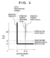
Fig. 5 is a graph showing the relationship between
the detection characteristics of the customer's ground
fault interrupter 3 and the detection conditions of the
ground fault detection level setting unit 42. The abscissa
represents the leakage current, and the ordinate represents
time. The customer's ground fault interrupter 3 used in
this embodiment has a rated operation current of 30 mA, a
rated non-operation current of 15 mA, and a rated operation
time of 100 ms. A current was flowed through the customer's
ground fault interrupter 3, and conditions under which the
customer's ground fault interrupter 3 actually operated
were measured to find that the operation current was 28 mA
and the operation time was 50 ms.
Since the rated non-operation current of a general
ground fault interrupter is determined, setting almost the
same detection sensitivity enables the customer's ground
fault interrupter 3 to reliably detect a ground fault at
a higher sensitivity than the general ground fault
interrupter. This embodiment sets a detection sensitivity
of 15 mA. Alternatively, the detection sensitivity may be
set to a value close to the measured value of the operation
sensitivity of the ground fault interrupter. Note that if
the detection sensitivity is set too high, the customer's
ground fault interrupter 3 may detect a leakage current
which is generated in normal running operation and passes
through the ground capacitor 6. Thus, an operation
sensitivity with a margin for the leakage current passing
through the ground capacitor 6 should be set.
The detection time must be set shorter than the
measured value of the operation time of the customer's
ground fault interrupter 3. Since the measured value of
the operation time of the customer's ground fault
interrupter 3 was 50 ms, this embodiment sets 2/3 the
measured value, i.e., 33 ms. If the detection time is too
short, the customer's ground fault interrupter 3 may
erroneously detect a transient phenomenon, so that a time
of about several ten ms is desirable. Even with the use
of a time delay type ground fault interrupter, the detection
time is set shorter than the measured value of the operation
time. If the detection time is set to about several ten
to hundred ms, the margin for the operation time increases
to improve the reliability of preventing unwanted
interruption operation of the customer's ground fault
interrupter 3.
The ground fault detection level setting unit 42
comprises switches for setting the detection sensitivity
and detection time, and selects conditions assigned to
these switches. The ground fault detection level setting
unit 42 can take various arrangements other than the
above-described one. For example, the ground fault
detection level setting unit 42 may adopt a switch for
incrementing/decrementing set parameters while referring
to set parameters displayed on the display.
In Fig. 3, reference numeral 43 denotes a nonvolatile
memory from/in which the control circuit 40 can read/write
information, and at least detection of a ground fault is
recorded. An example of the nonvolatile memory 43 is a
combination of a flash memory, an EEPROM, a backup power
supply such as a battery or electric double layer capacitor,
and a SRAM. Some CPUs incorporate flash memories and
EEPROMs. Using such a CPU can downsize and simplify the
nonvolatile memory 43.
Reference numeral 44 denotes an alarm unit used by
the control circuit 40 to inform at least detection of a
ground fault. The type of alarm unit 44 includes a method
of informing detection of a ground fault by sound using a
buzzer or speaker, and a method of informing it by light
using an LED or liquid crystal. In addition to the
presence/absence of sound or light, the alarm unit 44 may
display information by speech, characters, and symbols.
Alternatively, the alarm unit 44 may transmit information
to the outside of the customer's premises such as an
electric power company via a communication means.
Although not shown, a driving circuit for driving
each switching element, and a control power supply for
supplying power to the control circuit 40 or the like are
also necessary.
The control circuit 40 receives various signals from
the input and output sides of the power conditioner 2.
However, these signals must be insulated from both or at
least one of the input and output.
[Ground Fault Detection Operation]
Ground fault detection operation of the power
conditioner 2 will be explained.
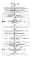
Fig. 4 is a flow chart showing ground fault detection
operation of the power conditioner 2 that is executed by
the control circuit 40.
In step S1, the control circuit 40 reads the detection
sensitivity and detection time of ground fault detection
from the ground fault detection level setting unit 42. In
step S2, the control circuit 40 sets the read detection
sensitivity as the reference value of the level comparator
of the ground fault determination unit 41. In step S3, the
control circuit 40 initializes the timer of the ground fault
determination unit 41, and starts counting.
In step S4, the control circuit 40 acquires the
comparison result between a zero-phase'current detection
value and the detection sensitivity by the level comparator
of the ground fault determination unit 41. If the
zero-phase current detection value < the detection
sensitivity, the control circuit 40 determines no ground
fault state, and returns to step S3. In other words, the
control circuit 40 repeats steps S3 and S4 while the
zero-phase current detection value is smaller than the
detection sensitivity. If the zero-phase current
detection value ≧ the detection sensitivity, the control
circuit 40 determines the possibility of a ground fault,
and advances to step S5.
In step S5, the control circuit 40 acquires the count
value of the timer of the ground fault determination unit
41. If a time represented by the count value < the detection
time, the control circuit 40 returns to step S4. That is,
even if the zero-phase current detection value is larger
than the detection sensitivity, the control circuit 40
repeats steps S4 and S5 while the count value of the timer
is smaller than the detection time. If the time represented
by the count value of the timer ≧ the detection time, the
control circuit 40 determines a ground fault, and shifts
to step S6.
In step S6, the control circuit 40 blocks the gate
of the inverter 12, opens the switch 14, and stops an
alternate current output. Note that switching operation
of the converter 11 is maintained to set the output voltage
to a predetermined voltage.
In step S7, the control circuit 40 initializes its
timer, and starts counting.
In step S8, the control circuit 40 determines from
the count value of its timer whether a time by which the
switch 14 is reliably opened (to be referred to as an "open
completion time" hereinafter) or longer has elapsed. If
NO in step S8, the control circuit 40 repeats step S8.
If YES in step S8, the control circuit 40 blocks the
gate of the converter 11 in step S9. Accordingly, running
stop operation of the power conditioner 2 is completed.
In step S10, the control circuit 40 records detection
of the ground fault in the nonvolatile memory 43. Detection
of the ground fault including data representing the
detection time and date, power generation amount, and
zero-phase current detection value is recorded in the
nonvolatile memory 43, which can be used as a reference in
investigating the cause of the stop of the power conditioner
2 later.
In step S11, the control circuit 40 determines
whether ground faults have successively occurred. If NO
in step S11, the control circuit 40 returns to step S3; or
if YES in step S11, shifts to step S12 to operate the alarm
unit 44 to inform the customer's premises of generation of
ground faults. Then, the control circuit 40 returns to step
S3 to repeat the above operation.
Generation of successive ground faults can be
determined by various methods. For example, the following
method can be employed.
A flag is prepared, and normally reset. When a ground
fault is detected, the flag is set, and is reset a
predetermined time after detection of a ground fault.
Hence, if a ground fault is detected again while the flag
is set, successive ground faults are determined. As
another method, the number of detected ground faults may
be counted. Alternatively, whether successive ground
faults occur may be determined using data representing the
detection time and date recorded in the nonvolatile memory
43. By processing detection of ground faults a plurality
of number of times by a predetermined method, whether ground
faults successively occur can be known.
Although an operation after recording of ground fault
detection or informing operation is not shown, the control
circuit 40 determines after a predetermined time that the
ground fault state is canceled, stops informing operation,
and resumes running the power conditioner 2.
Alternatively, for example, running of the power
conditioner 2 may be resumed by a manual operation, and
informing operation continues till the manual operation.
By the above operation, entrance of a ground fault
current can be reliably inhibited within a short time to
prevent unwanted interruption operation of the customer's
ground fault interrupter 3. More specifically, as
described above, the ground fault current is detected
within a short time, the gate of the inverter 12 is blocked,
and the switch14 is opened. At the same time, the operation
of the converter 11 is maintained to hold the input voltage
of the inverter 12 at a value larger than the peak value
of the alternate current voltage of the low-voltage
distribution system 4. After the switch 14 is reliably
opened, the gate of the converter 11 is blocked. Thus, the
ground fault current entering via the ground capacitor 6
of the solar battery array 1 can be reliably inhibited
within a short time to prevent unwanted interruption
operation of the customer's ground fault interrupter 3.
Since a semiconductor switch such as a fast-operation
solid state relay (SSR) need not be added to each phase of
the low-voltage distribution system 4, a solar power
generation apparatus can be constituted at a low loss and
low cost.
Since ground fault detection conditions can be
externally set, they can be adjusted in accordance with the
characteristics of the customer's ground fault interrupter
3 installed in the customer's premises. This enables
ground fault detection copying with the characteristics of
the customer's ground fault interrupter 3, resulting in a
high effect of preventing unwanted interruption operation
-of the customer's ground fault interrupter 3 can be
enhanced.
Recording detection of a ground fault in the
nonvolatile memory 43 makes it easy to investigate the cause
of the stop of the power conditioner 2 later. The ground
fault detection time and date, zero-phase current detection
value, power generation amount, and the like are preferably
recorded together.
If the customer is informed of detection of a ground
fault, the customer can know generation of a ground fault
outside the customer's premises, and can take a measure of
canceling the ground fault outside the customer's premises
or minimizing damage caused by a power failure.
By detecting a plurality of alternate current ground
faults, whether alternate current ground faults
successively occur can be determined. The power
conditioner 2 is controlled in accordance with whether
alternate current ground faults successively occur,
thereby realizing a more appropriate operation. In
particular, the customer's premises who is informed of
generation of successive alternate current ground faults
can take a more reliable measure.
<Second Embodiment>
The second embodiment will be described. The
arrangement of the second embodiment is almost the same as
that of the first embodiment except for the following
points.
A ground fault detection level setting unit 42
similarly sets the detection time, but does not set any
detection sensitivity. Setting of the detection
sensitivity can be instructed to a control circuit 40 by
a switch which is arranged in the ground fault detection
level setting unit 42 and directs a detection sensitivity
setting mode.
The control circuit 40 has a function of setting a
detection sensitivity corresponding to a solar battery
array 1, more specifically, to a ground capacitor 6 upon
reception of a detection sensitivity setting command from
the ground fault detection level setting unit 42. When the
control circuit 40 does not receive any detection
sensitivity setting command, it performs the same operation
as in the first embodiment. The detection sensitivity
setting function will be explained.
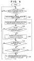
Fig. 6 is a flow chart showing detection sensitivity
setting operation which is executed by the control circuit
40.
If the control circuit 40 receives a detection
sensitivity setting command in step S21 (YES), it advances
to step S22 to shift to the detection sensitivity setting
mode. If NO in step S21, the control circuit 40 repeats
step S21.
In step S22, the control circuit 40 initializes its
timer in order to count the time after the detection
sensitivity setting mode is set, and starts counting. In
step S23, the control circuit 40 receives a zero-phase
current detection value from a zero-phase current detector
35 as a present detection value. In step S24, the control
circuit 40 compares the present detection value with the
maximum value of the past detection value (to be referred
to as a "maximum detection value" hereinafter). If the
present detection value is larger, the control circuit 40
advances to step S25 to update the maximum detection value
to the present detection value. In step S26, the control
circuit 40 checks whether the detection sensitivity setting
mode is set. If YES in step S26, the control circuit 40
advances to step S27; and if NO, to step S28.
In step S27, the control circuit 40 refers to the count
value of the timer to check whether the time falls within
the setting mode time. If YES in step S27, the control
circuit 40 returns to step S23 to repeat the operation from
steps S23 to S26. If NO in step S27, the control circuit
40 advances to step S28.
In step S28, the control circuit 40 sets a detection
sensitivity on the basis of the maximum detection value
obtained by the above operation. For example, the control
circuit 40 sets a value four times the maximum detection
value as the detection sensitivity. After this setting,
the operation returns to step S21.
With the above operation, the control circuit 40 can
detect the maximum value of a leakage current in a normal
state, i.e., a current passing through the ground capacitor
6 in a normal state, thus setting a detection sensitivity
corresponding to the solar battery array 1. Although the
setting mode time is arbitrary, too long a time is
meaningless, and too short a time decreases the reliability
of the maximum value of a detected leakage current. In
general, the setting mode time is set to about several to
10 min.
A transformerless type power conditioner 2 was
connected to a 4-kW solar battery array 1, the detection
sensitivity was set on a clear day, and the solar battery
array 1 was operated to find a maximum detection value of
3.1 mA. From this, the detection sensitivity was set to
12.4 mA. This detection sensitivity has a sufficient
margin for the actual operation sensitivity of a general
customer's ground fault interrupter 3, and can prevent
unwanted interruption operation of the customer's ground
fault interrupter 3. Since the detection sensitivity is
set four times the maximum detection value, it also has a
margin for a leakage current flowing through the ground
capacitor 6 in a normal state, and can suppress erroneous
stop of the power conditioner 2.
In this manner, a detection sensitivity
corresponding to the solar battery array 1 can be set by
measuring a leakage current in a normal state, and setting
the detection sensitivity on the basis of the maximum value.
Unwanted interruption operation of the customer's ground
fault interrupter 3-can be prevented, and erroneous stop
of the power conditioner 2 can be suppressed.
In the above description, the detection sensitivity
is set four times the maximum detection value on a clear
day. However, the detection sensitivity is not limited to
this, and can be arbitrarily set. Alternatively, a
plurality of detection sensitivity setting methods may be
adopted and selected. Depending on the type of solar
battery module, the influence of increasing a leakage
current on a rainy day is large. In this case, it is
desirable to set the detection sensitivity on a rainy data
or set a large magnification.
In general, the leakage current in a normal state is
proportional to the output from the power conditioner 2.
Considering this, the maximum detection value is multiplied
by a ratio Pr/Po of an output Po from the power conditioner
2 when the maximum detection value is obtained, and a rated
maximum output Pr from the power conditioner 2, thereby
calculating a maximum detection value converted into the
rated maximum output from the power conditioner 2. The
detection sensitivity can be set based on this maximum
detection value to suppress the influence of the magnitude
of an output from the power conditioner 2.
The detection sensitivity setting function is not
only operated by a manual operation but also always operated
in normal running operation. The maximum detection values
of leakage currents can be obtained in various situations;
and the detection sensitivity can be more properly set. In
this case, a current entering upon a ground fault outside
the customer's premises and a leakage current in a normal
state must be discriminated. For example, when the
detection value abruptly increases, an output from the
power conditioner 2 is decreased, and whether the detection
value decreases in accordance with the decrease in output
is checked.
The detection sensitivity setting function in the
second embodiment and manual setting of the detection
sensitivity in the first embodiment may be adopted together.
For example, a lower one of the two detection sensitivities
is set as an actual detection sensitivity. When a detection
sensitivity value by the detection sensitivity setting
function exceeds a manually set detection sensitivity value,
the user is informed of these detection sensitivity values
so as to check them. This can increase the reliability of
preventing unwanted interruption operation of the
customer's ground fault interrupter 3, and can suppress
erroneous stop of the power conditioner 2.
<Third Embodiment>
The arrangement of the third embodiment is almost the
same as those of the first and second embodiments except
for the detection sensitivity setting method.
In running a power conditioner 2, a control circuit
40 of the third embodiment receives a zero-phase current
detection value from a zero-phase current detector 35. At
the same time, the control circuit 40 receives output power
from the power conditioner 2, and holds as a maximum
detection value the maximum value of the zero-phase current
detection value every output power (e.g., 0.1 kW pitch).
On the basis of the held maximum detection value, the
control circuit 40 sets a detection sensitivity
corresponding to output power from the power conditioner
2 at that time in a ground fault determination unit 41.
Fig. 7 is a graph showing the maximum detection value
and detection sensitivity when a power conditioner 2 having
a maximum output of 4.5 kW is connected to a 4.5-kW solar
battery array 1. The abscissa represents the output power,
and the ordinate represents the zero-phase current
detection value. A solid line A shown in Fig. 7 represents
the maximum detection value, and a solid line B represents
the set value of the detection sensitivity. The maximum
detection value A is proportional to output power. For
output power of 4.5 kW, the maximum detection value was 4.2
mA. The set value B of the detection sensitivity is
obtained by doubling the maximum detection value A (broken
line C shown in Fig. 7) and adding 5 mA. Doubling sets a
margin, and adding 5 mA ensures a margin for a small output.
By setting a detection sensitivity corresponding to
output power in this fashion, unwanted interruption
operation of a customer's ground fault interrupter 3 and
erroneous stop of the power conditioner 2 can be prevented.
This effect is enhanced when an output from the power
conditioner 2 is small. More specifically, a current value
smaller than an operation current value interrupted by the
customer's ground fault interrupter 3 is set as the
detection sensitivity to prevent unwanted interruption of
the customer's ground fault interrupter 3. If the
detection sensitivity is set low, unwanted interruption of
the customer's ground fault interrupter 3 hardly occurs,
but the power conditioner 2 erroneously stops at high
possibility. For this reason, as there is a proportional
relationship between a leakage current via the ground
capacitor 6 and an output from the power conditioner 2, the
detection sensitivity is made to be proportional to an
output from the power conditioner 2. This can prevent both
unwanted interruption operation of the customer's ground
fault interrupter 3 and erroneous stop of the power
conditioner 2.
The detection sensitivity calculation method of the
third embodiment is not limited to the above one, and can
be properly set. A plurality of calculation methods may
be employed.
The detection sensitivity setting function may be
manually operated. Since the detection sensitivity can be
set while the situation is checked, the influence of a
ground fault outside the customer's premises can be easily
determined.
The detection sensitivity setting function in the
third embodiment and setting of the detection sensitivity
in the first embodiment can be used together. For example,
a smaller one of detection sensitivity values set by the
two means is set as an actual detection sensitivity. When
a detection sensitivity value by the detection sensitivity
setting function exceeds a manually set detection
sensitivity value, the user is informed of these detection
sensitivity values so as to check them. This can increase
the reliability of preventing unwanted interruption
operation of the customer's ground fault interrupter 3, and
can suppress erroneous stop of the power conditioner 2.
The second and third embodiments may adopt a
detection sensitivity confirmation unit for displaying a
set detection sensitivity value. In this case, the
constructor of a solar power generation apparatus can
confirm whether the detection sensitivity to the customer's
ground fault interrupter 3 is appropriate. Note that the
detection sensitivity confirmation unit may be commonly
used as the alarm unit 44, which can decrease the cost.
If the ground fault determination unit 41 not only
detects a zero-phase current but also determines a ground
fault using the phase difference between the zero-phase
current and the ground voltage, whether a failure occurs
on the input-side circuit of the power conditioner 2 can
be determined to suppress erroneous detection.
If the ground fault determination unit 41 detects
variations in ground potential to determine a ground fault,
a ground fault can be detected even when the power
conditioner 2 stops. The power conditioner 2 can resume
running after the ground fault state is reliably canceled.
In reactivating the power conditioner 2 after a
ground fault is detected once, unwanted operation under the
influence of a transient leakage current is prevented by
holding an output in a zero state for a time longer than
the detection time of the customer's ground fault
interrupter 3 after the switch 14 is turned on. A ground
fault can be detected with a small leakage current by
gradually increasing the output. Hence, unwanted
operation of the customer's ground fault interrupter 3 can
be reliably prevented.
As described above, the system interconnect power
conditioner 2 in each of the above-described embodiments
detects generation of a ground fault outside the customer's
premises within a short time before the customer's ground
fault interrupter 3 performs interruption. The gate of
inverter is immediately blocked, the switch 14 is opened,
and the input voltage of the inverter is held to be higher
than the peak value of the alternate current voltage of the
system 4. A ground fault current entering the power
conditioner 2 is instantaneously, reliably interrupted to
prevent unwanted interruption operation of the customer's
ground fault interrupter 3. This can avoid a power failure
in the customer's premises caused by the ground fault
outside the customer's premises. Since a semiconductor
switch such as an SSR need not be added to each phase, the
power conditioner 2 can be constituted at a low loss and
low cost.
As many apparently widely different embodiments of
the present invention can be made without departing from
the spirit and scope thereof, it is to be understood that
the invention is not limited to the specific embodiments
thereof except as defined in the appended claims.
in a solar power generation apparatus using a solar
battery having a relatively large ground capacitor and a
power conditioner having a non-insulated input and output,
a customer's ground fault interrupter may perform unwanted
interruption due to a ground fault outside the customer's
premises. To prevent this, when a ground fault is detected
by a detector capable of detecting a ground fault within
a shorter time than the customer's ground fault interrupter,
the gate of inverter of the power conditioner is blocked,
a switch is changed to an open state, and the input voltage
of inverter is held at a voltage value higher than the peak
value of the alternate current voltage of a power system
until at least the switch changes to the open state.