EP1107427A2 - Rotary electric machine for vehicle - Google Patents
Rotary electric machine for vehicle Download PDFInfo
- Publication number
- EP1107427A2 EP1107427A2 EP00126859A EP00126859A EP1107427A2 EP 1107427 A2 EP1107427 A2 EP 1107427A2 EP 00126859 A EP00126859 A EP 00126859A EP 00126859 A EP00126859 A EP 00126859A EP 1107427 A2 EP1107427 A2 EP 1107427A2
- Authority
- EP
- European Patent Office
- Prior art keywords
- winding
- conductors
- electric machine
- rotary electric
- phase
- Prior art date
- Legal status (The legal status is an assumption and is not a legal conclusion. Google has not performed a legal analysis and makes no representation as to the accuracy of the status listed.)
- Granted
Links
Images


Classifications
-
- H—ELECTRICITY
- H02—GENERATION; CONVERSION OR DISTRIBUTION OF ELECTRIC POWER
- H02K—DYNAMO-ELECTRIC MACHINES
- H02K3/00—Details of windings
- H02K3/04—Windings characterised by the conductor shape, form or construction, e.g. with bar conductors
- H02K3/28—Layout of windings or of connections between windings
-
- H—ELECTRICITY
- H02—GENERATION; CONVERSION OR DISTRIBUTION OF ELECTRIC POWER
- H02K—DYNAMO-ELECTRIC MACHINES
- H02K3/00—Details of windings
- H02K3/04—Windings characterised by the conductor shape, form or construction, e.g. with bar conductors
- H02K3/12—Windings characterised by the conductor shape, form or construction, e.g. with bar conductors arranged in slots
Definitions
- the present invention relates to a rotary electric machine such as a motor or a generator to be mounted in a ship or a vehicle.
- hybrid vehicles have been manufactured in order to protect the environment.
- a hybrid vehicle is driven by a motor while running at a low speed in a town or the like and is driven by an engine while running at a high speed in a suburb.
- a hybrid vehicle such as a hybrid bus on a regular route, whose engine is switched off when the vehicle stops temporarily on a traffic signal.
- Such a hybrid bus is equipped with an idle-stop system for automatically stopping the engine.
- an inexpensive rotary electric machine that operates both as a motor and as a generator has been demanded to continuously drive a compressor and/or a power steering pump while the vehicle engine is stopped.
- WO98/54823 or U.S. Patent 5,998,903, which corresponds to WO98/54823 discloses a compact and powerful generator.
- Such a generator has a stator winding formed of a plurality of conductor segments, a stator core having two times as many slots as an ordinary generator.
- the conductor segments are connected so that one of the conductor segments that extended from one of a plurality of layers of a slot is connected to another that are extended from another layer of another slot.
- This arrangement improves the conductor's space-factor and cooling effect of the stator winding, resulting in a stator winding of low resistance.
- windings that are disposed in the neighboring slots are connected in series to be connected to a rectifier bridge to provide a DC output power.
- windings disposed in the neighboring slots are connected in parallel to be connected to respective rectifier bridges to provide a composite DC output power.
- a main object of the invention is to provide a vehicle rotary electric machine that has a stator winding having a large current capacity.
- Another object of the invention is to accommodate a small number of conductors in each slot and form a plurality winding sections connected in parallel, thereby increasing the current capacity of the stator winding.
- Another object of the invention is to provide new conductor segments that are suitable for forming a parallel circuit of the winding sections.
- Another object of the invention is to provide a vehicle rotary electric machine that can operate as both a motor and a generator.
- a phase-winding is formed of a plurality of parallel winding sections, each of which is comprised of a plurality of conductors. This plurality of conductors is distributed to a plurality of neighboring slots.
- the rotary electric machine can provide a sufficient torque characteristic, as a motor, and a sufficient output current characteristic, as a generator.
- a phase winding is formed of a first winding section and a second winding section.
- the first winding section includes a series circuit of a portion of a plurality of conductors disposed in one of the two neighboring slots and a portion of a plurality of conductors disposed in the other slot.
- the second winding section includes a series circuit of the remaining portion of the plurality of conductors disposed in the one slot and the remaining portion of the conductors disposed in the other slot.
- the first winding section may include a series circuit of a half of a plurality of conductors disposed in one of the two neighboring slots and a half of a plurality of conductors disposed in the other slot.
- the conductors of the first winding section and the conductors of the second winding section are connected in a manner corresponding to the phase angle, forming a diamond shape, which equalizes the phase angle of the first and second winding sections.
- the total number of the slot is equal to or more than p ⁇ n ⁇ m.
- a 16-pole, three-phase and two-neighboring-slot type rotary electric machine has 96 slots. This type can provide a suitable size of a vehicle rotary electric machine. If a rotary electric machine has some empty slots, the number of slots becomes more than 96.
- the above embodiment may include switch elements connected to the respective phase windings of the multi-phase stator winding.
- the number of the switch elements that are connected to respective phase windings is proportional to the number of the phases because each phase winding is formed of the winding sections connected to each other in parallel.
- three-phase stator winding is connected to a three-phase bridge circuit.
- This structure can make the number and the size of the switching elements small. It is desirable to use diodes as the switching elements.
- a rectifier can be formed of diodes, and an inverter can be formed of transistors or MOS transistors.
- the conductor may be a conductor segment connected at a coil end that is extended to an end of the stator core.
- the conductor segment is suitable to a stator having a small number of conductors in each slot.
- the conductors that are distributed to neighboring slots are connected in series to form a winding section, thereby providing a suitable number of coil-turns.
- a plurality of coil ends is extended to an end of the stator core and is spaced apart from one another. It is easy to line up the coil ends at a prescribed portion so that the coil ends can be spaced apart from each other. This arrangement is effective to lessen heat problems. It is also effective to provide an even arrangement of the coil ends. For example, it is possible to provide gaps for passing cooling air between the coil ends.
- the conductors disposed in the slots have a rectangular cross-section having longer radial sides.
- the vehicle rotary electric machine can be provided with a booster for boosting output voltage generated by the stator winding in a low speed range. Further, a switching device can be disposed in the rotary electric machine to repeat grounding and opening of the output terminal of the stator winding.
- vehicle generator-motor 1 as a vehicle rotary electric machine includes front frame 11 and rear frame 12.
- Front frame 11 and rear frame 12 rotatably support rotor 2 and also fixedly support stator 3.
- Rear frame 12 has output terminal 13.
- Shaft 21 of rotor 2 extends through front frame 11 and projects from frame 11 to have pulley 22 fixed at the left of front end thereof.
- Pulley 22 is linked to a vehicle drive engine via a belt (not shown).
- the right or rear end of shaft 21 projects backward from rear frame 12 to a portion where brush unit 14 is disposed.
- Brush unit 14 has a pair of brushes 15 disposed in contact with a pair of slip rings 23 that is carried by shaft 21.
- Shaft 21 carries Lundell-type magnetic core 24.
- Magnetic core 24 has a plurality of pole pieces 24a on the outer periphery thereof.
- Magnetic core 24 is comprised of front pole core 24b and rear pole core 24c.
- Magnetic field coil 25 is disposed between both pole cores 24b and 24c to polarize the plurality of pole pieces 24a.
- Field coil 25 is connected to the pair of slip rings 23 to be energized via brush unit 14.
- Magnetic core 23 has front fan 26 and rear fan 27, which are respectively fixed on the opposite ends thereof. Front and rear fans 26 and 27 take air from air-intake windows 16 and 17 formed at frames 11 and 12 and discharge the air from air discharge windows 18 and 19.
- Stator 3 is disposed opposite the plurality of pole pieces 24a of rotor 2.
- Stator 3 is a cylindrical member disposed around rotor 2.
- Stator 3 has stator core 31 that is formed of a plurality of laminated steel sheets and stator winding 32 mounted on stator core 31. One end of stator winding 32 is connected to output terminal 13 as output lead wire 33.
- stator core 31 has a plurality of axially extending slots 310.
- the plurality of slots 310 is formed to open at the inner periphery of stator core 31 opposite pole pieces 24a, where teeth 312 are also formed.
- Two conductors are disposed in each slot 311.
- Conductor 34 disposed in a radially inner layer and conductor 35 disposed in a radially outer layer are radially piled or stratified in each slot.
- Conductors 34 and 35 have a rectangular cross-section whose radial sides are longer than the circumferential sides so that wider teeth can be provided.
- the wide teeth provide excellent heat conduction from conductors to the stator and a suitable distance between respective coil ends outside the slots.
- Insulators 36 of a thin insulation sheet are respectively disposed between conductors 34, 35 and the inner surfaces of slots 311.
- Stator winding 32 is formed of conductors 34 and 35 respectively disposed in the inner and outer layers of a plurality of slots 311.
- the plurality of slots 311 forms six groups that are different in electric phase from one another.
- the first slot group includes slots #4, #10, #16 - #88 and #94 (slot numbers indicated in the middle of the winding diagrams)
- the second slot group includes #5, #11, #17 - #89 and #95, as shown in Figs 3 and 4.
- the third, fourth, fifth and sixth slot groups are disposed in the stator core in the same manner.
- the first and second slot groups are disposed neighbor to each other and accommodate an X-phase winding.
- the third and fourth slot groups are disposed next or neighbor to each other and accommodate a Y-phase winding
- the fifth and sixth slot groups are disposed neighbor to each other and accommodate a Z-phase winding.
- conductors 34 and 35 are alternately connected in series.
- one of conductors 34 and 35 accommodated in a slot is series-connected to the other of conductors 34 and 35 accommodated in another slot that is six-slot-pitch spaced apart from the aforestated slot.
- twelve wave-wound winding units that round stator core 32 are formed.
- Two conductors accommodated in a slot are respectively connected to other conductors to form two wave-wound winding units.
- the first slot group accommodates two wave-wound winding units 37a and 38a.
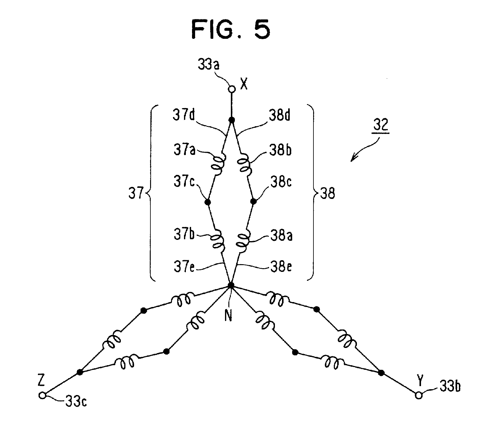
- Two winding units 37a and 37b which are accommodated in the neighboring first and second slot groups, are connected in series by crossing wire 37c to form winding section 37. Accordingly, a plurality of conductors of winding section 37 is distributed to two neighboring slot groups. Opposite ends 37d and 37e of winding section 37 are extended in the axial direction from coil ends. Remaining two winding units 38a and 38b of all the four wave-wound winding units accommodated in the first and second slot groups are series-connected by crossing wire 38c to form winding section 38. Opposite ends 38d and 38e of winding section 38 are extended in the axial direction from coil ends. Ends 37d and 38d are connected to each other and to X-phase output terminal 33a.
- end 37e and end 38e are connected to each other to form a neutral point N.
- two winding sections 36 and 37 accommodated in the two neighboring slot groups are connected in parallel.
- the X-phase winding having two conductors each slot is formed.
- Y-phase winding and Z-phase winding are also formed in the same manner as described above.
- Winding section 37 and winding section 38 generate voltage in the same phase at the opposite ends. Therefore, the voltages in vector can be illustrated in a diamond shape, as shown in Fig. 5, which illustrates voltages in vector of the star connected X, Y and Z-phase windings. Thus, a three-phase winding can be formed of six different winding sections.
- Control unit 4 is connected to a vehicle battery.
- Control unit 4 includes a three-phase bridge circuit comprised of MOS-FETS and a control circuit for controlling the gate voltage of the MOS-FETS and field current, as shown in Fig. 6.
- Control unit 4 operates rotary electric machine 1 as a three-phase AC generator or a three-phase synchronous motor according to the vehicle running conditions or electric load conditions.
- control unit 4 has a function to convert alternating current to direct current and a function to switch on or off current that is supplied to the armature winding.
- Inner conductors 34 and outer conductors 35 are formed of conductor segments, and a plurality of conductor segments is connected in series to form a series-connected winding. As shown in Figs. 7 and 8, most portion of the stator winding is comprised of U-shaped conductor segments 30, and the ends of the stator winding 37d, 37e, 38d and 38e are comprised of I-shaped conductor segments. Crossing wires 37c and 38c are comprised of U-shaped conductor segments the span of which is one slot-pitch shorter than a pole pitch. All the conductor segments are made of film-coated copper wires as shown in Fig. 2.
- conductor segment 30 is formed of a copper wire, which is bent to form hairpin-shaped segment 30a, thereafter, twisted at portions A near turn portion 30b, and twisted at portions B near the ends thereof. Portions A are twisted before the segments are mounted in stator core 31, and portions B are twisted after the segments are mounted in stator core 31.
- Turn portion 30b and inclined portions 30c and 30d of conductor segments 30 form a coil end 30m on an end of stator winding 32.
- Inclined portions 30g and 30h and segment ends 30i and 30j form another coil end 30n on the other end of stator winding 32.
- Segment ends 30i and 30j of one conductor segment 30 are respectively connected to the segment ends of other conductor segments by welding, forming joint portions 39.
- Straight portion 30e is disposed in one slot 311 as inner conductor34
- straight portion 30f is disposed in another slot 311 as outer conductor 35.
- the one slot 311 and the another slot 311 are a predetermined number of pole-pitches spaced from each other.
- a plurality of coil ends 30m forms a ring-shaped coil-end group.
- Each of the plurality of coil ends 30m is spaced apart from another to form gaps, which cooling air is taken in.
- control unit 4 When the rotary electric machine operates as a motor, direct current is supplied from a battery to control unit 4, which provides a three-phase AC voltage through its switching operation.
- the three-phase AC voltage is applied to stator winding 32 to form a rotating magnetic field, which rotates rotor 2 as a magnetic rotor member.
- the rotary electric machine has six phase-windings (wave-wound winding sections). However, a three-phase bridge circuit of the control unit, which is more compact and inexpensive, can be used.
- the rotary electric machine has a stator core in which winding sections are disposed 30° in electric angle different from each other. Therefore, magnetic pulsation can be moderated so that noises can be reduced.
- the conductor segments shown in Fig. 7 it is possible to use the conductor segments according to a third embodiment of the invention, as shown in Fig. 10.
- the number of conductors in each slot is four.
- the number of the conductors can be selected according to the driving torque and the output electric power.
- Conductor segments 300 are mainly formed of large segments 301 and small segments 302. Therefore, four conductors are lined up along a radial direction in each slot as illustrated by broken lines in Fig. 10.
- one slot-group has two two-turn lap-wound winding units. It is also possible to form four wave-wound winding units.
- the same-phase winding sections can be formed of either wave-wound winding units or lap-wound winding units.
- a half of the conductor segments accommodated in one of neighboring two slot groups and a half of the conductor segments accommodated in the other group are connected in series to form a winding section.
- two winding sections are connected in parallel to each other to form a phase winding.
- Insulators 360 are preferably curled into columnar members as shown in Fig. 10.
- a rotary electric machine has a battery charging system shown in Fig. 11.
- the battery charging system has booster 41 for boosting output voltage of control unit 401 up to a voltage higher than a battery voltage.
- Booster 41 is controlled by control unit 401.
- Control unit 401 controls the generator output voltage to provide a maximum electric power while the engine rotation speed is in a low speed range.
- control unit 401 controls booster 41 to boost the output voltage thereof, thereby charging the battery. For example, when the rotary electric machine rotates at a low speed, such as speed N1 or N2 in Fig. 12, the output voltage is lowered to voltage V1 or V2 that is lower than the battery voltage VB.
- Fig. 12 shows generator output power in Y-axis and generator output voltage in X-axis when the engine speed is N1 and N2 (N1 ⁇ N2).
- the above described structure is effective to supplement the generator output power in case the number of conductors in each slot is so small that the generator output power is not high enough in a low speed range.
- This structure is well fit for an idle-stop system that stops a vehicle engine temporarily when the engine runs at an idling speed.
- a battery charging system of a rotary electric machine according to a fifth embodiment of the invention is shown in Fig. 13.
- the battery charging system is equipped with switch element 42 for grounding the output voltage of control unit 402.
- This battery charging system controls switch element 42 to repeat the switching operation, thereby generating voltage Vo that is higher than battery voltage Vb so as to charge a battery. This also can supplement the generation power in a low speed range.
- induced voltage by repeated switching operation of grounding the output terminal is set to a voltage that corresponds to a maximum output power.
- the output power in a low speed range can be increased.
Landscapes
- Engineering & Computer Science (AREA)
- Power Engineering (AREA)
- Windings For Motors And Generators (AREA)
Abstract
Description
Claims (11)
- A vehicle rotary electric machine comprising:a rotor (2) having a plurality of magnetic poles;a stator having a stator core (31) opposed to said rotor (2) and a multi-phase stator winding (32), said stator core (31) having a plurality of slots (311) accommodating a plurality of conductors connected to form said stator winding (32);a frame (11, 12) for supporting said rotor (2) and stator, whereinsaid multi-phase stator winding (32) comprises a plurality of phase-windings (X, Y, Z); characterized in thateach of said plurality of phase-windings (X, Y, Z) comprises a plurality of parallel-connected winding sections (37, 38), andeach winding section (37, 38) comprises a plurality of series-connected conductors (34, 35) distributed to those of said plurality of slots (311) that is neighbor to each other.
- The vehicle rotary electric machine as claimed in claim 1, characterized in that
said plurality of winding sections (37, 38) is the same in phase with one another at opposite ends (37d-37e, 38ed-38e) to be connected in parallel. - The vehicle rotary electric machine as claimed in claim 1, characterized in thatsaid plurality of phase winding sections (37, 38) has a first winding section (37) and a second winding section (38),said first winding section (37) comprises a series circuit of a portion of a plurality of conductors (34, 35) disposed in one of said two neighboring slots (311) and a portion of a plurality of conductors (34, 35) disposed in the other slot, andsaid second winding section (38) comprises a series circuit of the remaining portion of said plurality of conductors (34, 35) disposed in said one slot (311) and the remaining portion of said conductors (34, 35) disposed in said the other slot (311).
- The vehicle rotary electric machine as claimed in claim 3, characterized in that
said first winding section (37) comprises a series circuit of a half of a plurality of conductors (34, 35) disposed in one of said two neighboring slots (311) and a half of a plurality of conductors (34, 35) disposed in said the other slots (311). - The vehicle rotary electric machine as claimed in claim 1, wherein
if the number of poles of said rotor (2) is p, the number of phases of said multi-phase stator winding (32) is n, the number of the neighboring slots (311) for accommodating conductors (34, 35) of said phase-winding (X, Y, Z) of said stator winding (32) is m, the total number of said slots (311) is equal to or more than p x n x m. - The vehicle rotary electric machine as claimed in claim 1, characterized by
a plurality of switch elements (a, b, c, d, e, f, in Fig. 6) connected to respective phase windings of said multi-phase stator winding (32). - The vehicle rotary electric machine as claimed in claim 1, characterized in that
said plurality of conductors (34, 35) comprises a plurality of conductor segments (30, 300, 301, 302) connected at coil ends extended to an end of said stator core (31). - The vehicle rotary electric machine as claimed in claim 7, characterized in that
said end of said stator core (31) has a plurality of coil ends extended to spaced apart from one another. - The vehicle rotary electric machine as claimed in claim 1, characterized in that
said conductors (34, 35) disposed in said slots (311) have a rectangular cross-section having radial sides longer than circumferential sides. - The vehicle rotary electric machine as claimed in claim 1, characterized by a booster (41) for boosting output voltage generated by said stator winding (32) when running in a low speed range.
- The vehicle rotary electric machine as claimed in claim 1, characterized by a switching device (42) which repeats grounding and opening of the output terminal of said stator winding (32).
Applications Claiming Priority (2)
| Application Number | Priority Date | Filing Date | Title |
|---|---|---|---|
| JP35007499 | 1999-12-09 | ||
| JP35007499A JP4450125B2 (en) | 1999-12-09 | 1999-12-09 | Rotating electric machine for vehicles |
Publications (3)
| Publication Number | Publication Date |
|---|---|
| EP1107427A2 true EP1107427A2 (en) | 2001-06-13 |
| EP1107427A3 EP1107427A3 (en) | 2002-05-22 |
| EP1107427B1 EP1107427B1 (en) | 2005-02-09 |
Family
ID=18408062
Family Applications (1)
| Application Number | Title | Priority Date | Filing Date |
|---|---|---|---|
| EP00126859A Expired - Lifetime EP1107427B1 (en) | 1999-12-09 | 2000-12-07 | Rotary electric machine for vehicle |
Country Status (4)
| Country | Link |
|---|---|
| US (1) | US6417592B2 (en) |
| EP (1) | EP1107427B1 (en) |
| JP (1) | JP4450125B2 (en) |
| DE (1) | DE60018022T2 (en) |
Cited By (8)
| Publication number | Priority date | Publication date | Assignee | Title |
|---|---|---|---|---|
| EP1376828A1 (en) * | 2002-06-25 | 2004-01-02 | Denso Corporation | Sequentially joined-segment coil for rotary electrical machine with high degree of electrical insulation |
| FR2842363A1 (en) * | 2002-07-15 | 2004-01-16 | Denso Corp | ELECTRIC ROTATING MACHINE OF STATOR COIL TYPE WITH SEQUENTIAL SEGMENT JUNCTIONS |
| EP1381140A3 (en) * | 2002-06-12 | 2004-08-04 | Denso Corporation | Sequentially joined-segment coil for rotary electrical machine |
| EP1401084A3 (en) * | 2002-09-18 | 2005-01-12 | Denso Corporation | Sequentially joined-segment armature and ac machine using same |
| WO2005117238A1 (en) | 2004-05-19 | 2005-12-08 | Visteon Global Technologies, Inc | Electrical machine having a stator winding with a plurality of filars |
| WO2007077236A1 (en) * | 2005-12-30 | 2007-07-12 | Robert Bosch Gmbh | Electric machine |
| EP2698901A4 (en) * | 2011-12-02 | 2016-07-27 | Lg Electronics Inc | STATOR OF ELECTRIC MACHINE, ELECTRIC MOTOR EQUIPPED WITH THIS STATOR AND ELECTRIC VEHICLE EQUIPPED WITH THE ELECTRIC MOTOR |
| CN109327093A (en) * | 2017-08-01 | 2019-02-12 | 上海鸣志电器股份有限公司 | A kind of nested winding for non-gullet motor |
Families Citing this family (95)
| Publication number | Priority date | Publication date | Assignee | Title |
|---|---|---|---|---|
| JP3621635B2 (en) * | 2000-08-10 | 2005-02-16 | 三菱電機株式会社 | Rotating electric machine |
| DE60228200D1 (en) * | 2001-02-16 | 2008-09-25 | Omron Tateisi Electronics Co | ENERGY SYSTEM WITH A GENERATOR DRIVEN BY A MOTOR |
| JP3633494B2 (en) * | 2001-02-20 | 2005-03-30 | 株式会社デンソー | Rotating electric machine |
| US20030057789A1 (en) * | 2001-09-21 | 2003-03-27 | Buening Duane Joseph | Five phase alternating current generator |
| JP3668938B2 (en) * | 2001-12-11 | 2005-07-06 | 三菱電機株式会社 | Rotating electric machine |
| JP3858698B2 (en) * | 2002-01-11 | 2006-12-20 | 株式会社デンソー | AC generator for vehicles |
| GB2389717B (en) * | 2002-01-24 | 2004-07-28 | Visteon Global Tech Inc | Automotive alternator stator assembly and winding method |
| US6750581B2 (en) | 2002-01-24 | 2004-06-15 | Visteon Global Technologies, Inc. | Automotive alternator stator assembly with rectangular continuous wire |
| US7129612B2 (en) * | 2002-01-24 | 2006-10-31 | Visteon Global Technologies, Inc. | Stator assembly with cascaded winding and method of making same |
| US6882077B2 (en) * | 2002-12-19 | 2005-04-19 | Visteon Global Technologies, Inc. | Stator winding having cascaded end loops |
| US6930426B2 (en) * | 2003-11-26 | 2005-08-16 | Visteon Global Technologies, Inc. | Alternator stator having a multiple filar construction to improve convective cooling |
| US7170211B2 (en) * | 2002-01-24 | 2007-01-30 | Visteon Global Technologies, Inc. | Stator winding having transitions |
| JP3960122B2 (en) * | 2002-05-01 | 2007-08-15 | 株式会社デンソー | Electric compressor |
| JP3590623B2 (en) | 2002-05-23 | 2004-11-17 | 三菱電機株式会社 | AC rotating electric machine for vehicles |
| US20040070305A1 (en) * | 2002-10-15 | 2004-04-15 | Neet Kirk E. | Stator for an automobile alternator and method |
| US20040119359A1 (en) * | 2002-12-19 | 2004-06-24 | Visteon Global Technologies, Inc. | Automotive alternator stator assembly with odd number of electrical turns |
| US6949857B2 (en) * | 2003-03-14 | 2005-09-27 | Visteon Global Technologies, Inc. | Stator of a rotary electric machine having stacked core teeth |
| DE10329572A1 (en) * | 2003-06-30 | 2005-01-20 | Robert Bosch Gmbh | Process for producing an electromagnetically excitable core |
| US6922001B2 (en) | 2003-12-02 | 2005-07-26 | Visteon Global Technologies, Inc. | Process for assembling an alternator stator with clips that allows radial insertion of square wire with small slot openings |
| US7081697B2 (en) | 2004-06-16 | 2006-07-25 | Visteon Global Technologies, Inc. | Dynamoelectric machine stator core with mini caps |
| US7386931B2 (en) * | 2004-07-21 | 2008-06-17 | Visteon Global Technologies, Inc. | Method of forming cascaded stator winding |
| JP4112535B2 (en) | 2004-07-30 | 2008-07-02 | 株式会社一宮電機 | Stator and brushless motor |
| US7269888B2 (en) * | 2004-08-10 | 2007-09-18 | Visteon Global Technologies, Inc. | Method of making cascaded multilayer stator winding with interleaved transitions |
| US7075206B1 (en) * | 2005-02-07 | 2006-07-11 | Visteon Global Technologies, Inc. | Vehicle alternator stator winding having dual slot configuration |
| JP4634193B2 (en) | 2005-03-14 | 2011-02-16 | 日立オートモティブシステムズ株式会社 | Synchronous motor |
| JP2006248469A (en) | 2005-03-14 | 2006-09-21 | Hitachi Ltd | Electric four-wheel drive vehicle and its control device |
| RU2366062C2 (en) * | 2005-03-31 | 2009-08-27 | Альстом Текнолоджи Лтд | Generator with high phase order |
| US7365467B2 (en) * | 2005-04-06 | 2008-04-29 | Visteon Global Technologies, Inc. | Low noise stator winding having a phase angle shift |
| US7318270B1 (en) * | 2005-04-14 | 2008-01-15 | United States Of America As Represented By The Secretary Of The Air Force | Method for producing a full wave bridge rectifier suitable for low-voltage, high-current operation |
| DE102005023363A1 (en) * | 2005-05-20 | 2006-11-23 | Robert Bosch Gmbh | Five-phase generator |
| US7536526B2 (en) * | 2005-07-11 | 2009-05-19 | General Electric Company | Hierarchical state based migration of structured data |
| JP4839840B2 (en) * | 2006-01-04 | 2011-12-21 | 株式会社日立製作所 | Rotating electric machine |
| US7432626B2 (en) | 2006-02-03 | 2008-10-07 | Remy International, Inc. | Dynamoelectric machine having reduced magnetic noise and method |
| US7911106B2 (en) * | 2007-03-29 | 2011-03-22 | Hitachi, Ltd. | Rotary electric machine |
| US7876016B2 (en) * | 2007-11-15 | 2011-01-25 | Sundyne Corporation | Stator winding method and apparatus |
| GB2462257B (en) * | 2008-07-29 | 2010-09-29 | Clean Current Power Systems | Electrical machine with dual insulated coil assembly |
| US8928292B2 (en) * | 2008-08-22 | 2015-01-06 | Drs Power & Control Technologies, Inc. | Multiple voltage generator and voltage regulation methodology for power dense integrated power systems |
| US7913375B2 (en) * | 2009-01-19 | 2011-03-29 | Sergey Pulnikov | Method for making electrical windings for electrical machines and winding obtained by said method |
| JP4715934B2 (en) * | 2009-02-20 | 2011-07-06 | 株式会社デンソー | 5-phase motor |
| JP5070248B2 (en) * | 2009-06-30 | 2012-11-07 | 日立オートモティブシステムズ株式会社 | Rotating electric machine and manufacturing method thereof |
| JP5656436B2 (en) * | 2010-03-31 | 2015-01-21 | 国産電機株式会社 | Stator coils, rotating electrical machines and automobiles |
| MX2012011571A (en) | 2010-05-04 | 2013-02-12 | Remy Technologies Llc | Electric machine cooling system and method. |
| US8659191B2 (en) | 2010-05-18 | 2014-02-25 | Remy Technologies, Llc | Sleeve member for an electric machine |
| CN103038983B (en) | 2010-06-04 | 2016-08-10 | 瑞美技术有限责任公司 | Electromotor cooling system and method |
| JP2013528353A (en) | 2010-06-08 | 2013-07-08 | レミー テクノロジーズ リミテッド ライアビリティー カンパニー | Electromechanical cooling system and method |
| US8269383B2 (en) * | 2010-06-08 | 2012-09-18 | Remy Technologies, Llc | Electric machine cooling system and method |
| US8456046B2 (en) * | 2010-06-08 | 2013-06-04 | Remy Technologies, Llc | Gravity fed oil cooling for an electric machine |
| US8519581B2 (en) | 2010-06-08 | 2013-08-27 | Remy Technologies, Llc | Electric machine cooling system and method |
| US8482169B2 (en) | 2010-06-14 | 2013-07-09 | Remy Technologies, Llc | Electric machine cooling system and method |
| US8614538B2 (en) | 2010-06-14 | 2013-12-24 | Remy Technologies, Llc | Electric machine cooling system and method |
| US8552600B2 (en) | 2010-06-14 | 2013-10-08 | Remy Technologies, Llc | Potted end turns of an electric machine |
| US8446056B2 (en) | 2010-09-29 | 2013-05-21 | Remy Technologies, Llc | Electric machine cooling system and method |
| US8395287B2 (en) | 2010-10-04 | 2013-03-12 | Remy Technologies, Llc | Coolant channels for electric machine stator |
| US8593021B2 (en) | 2010-10-04 | 2013-11-26 | Remy Technologies, Llc | Coolant drainage system and method for electric machines |
| US8508085B2 (en) | 2010-10-04 | 2013-08-13 | Remy Technologies, Llc | Internal cooling of stator assembly in an electric machine |
| US8492952B2 (en) | 2010-10-04 | 2013-07-23 | Remy Technologies, Llc | Coolant channels for electric machine stator |
| US8546983B2 (en) | 2010-10-14 | 2013-10-01 | Remy Technologies, Llc | Split drain system and method for an electric machine module |
| US8648506B2 (en) | 2010-11-09 | 2014-02-11 | Remy Technologies, Llc | Rotor lamination cooling system and method |
| JP5354302B2 (en) | 2010-12-13 | 2013-11-27 | 株式会社デンソー | Rotating electric machine stator |
| US8497608B2 (en) | 2011-01-28 | 2013-07-30 | Remy Technologies, Llc | Electric machine cooling system and method |
| JP5289499B2 (en) * | 2011-04-01 | 2013-09-11 | 三菱電機株式会社 | Rotating electric machine |
| WO2012145302A2 (en) | 2011-04-18 | 2012-10-26 | Remy Technologies, Llc | Electric machine module cooling system and method |
| US8692425B2 (en) | 2011-05-10 | 2014-04-08 | Remy Technologies, Llc | Cooling combinations for electric machines |
| WO2012167274A1 (en) | 2011-06-03 | 2012-12-06 | Remy Technologies, Llc | Electric machine module cooling system and method |
| US9041260B2 (en) | 2011-07-08 | 2015-05-26 | Remy Technologies, Llc | Cooling system and method for an electronic machine |
| US8803381B2 (en) | 2011-07-11 | 2014-08-12 | Remy Technologies, Llc | Electric machine with cooling pipe coiled around stator assembly |
| US8546982B2 (en) | 2011-07-12 | 2013-10-01 | Remy Technologies, Llc | Electric machine module cooling system and method |
| US9048710B2 (en) | 2011-08-29 | 2015-06-02 | Remy Technologies, Llc | Electric machine module cooling system and method |
| US8975792B2 (en) | 2011-09-13 | 2015-03-10 | Remy Technologies, Llc | Electric machine module cooling system and method |
| US8901789B2 (en) | 2011-10-07 | 2014-12-02 | Remy Technologies, Llc | Electric machine module |
| US9099900B2 (en) | 2011-12-06 | 2015-08-04 | Remy Technologies, Llc | Electric machine module cooling system and method |
| JP5948061B2 (en) | 2012-01-19 | 2016-07-06 | 日立オートモティブシステムズ株式会社 | Rotating electric machine and vehicle equipped with the rotating electric machine |
| US9331543B2 (en) | 2012-04-05 | 2016-05-03 | Remy Technologies, Llc | Electric machine module cooling system and method |
| US10069375B2 (en) | 2012-05-02 | 2018-09-04 | Borgwarner Inc. | Electric machine module cooling system and method |
| US20140033514A1 (en) * | 2012-08-06 | 2014-02-06 | Remy Technologies, Llc | Electric machine with single or dual-shape winding configuration and method |
| US9379586B2 (en) | 2013-04-24 | 2016-06-28 | GM Global Technology Operations LLC | Bar wound stator winding layout with long-pitched and short-pitched coils |
| EP2852038A1 (en) * | 2013-09-20 | 2015-03-25 | Siemens Aktiengesellschaft | Electric generator arrangement and method for reducing a rotor eccentricity |
| JP5954591B2 (en) | 2014-02-07 | 2016-07-20 | 株式会社デンソー | Rotating electric machine stator |
| JP6209984B2 (en) * | 2014-02-07 | 2017-10-11 | マツダ株式会社 | Stator winding structure and stator manufacturing method |
| JP6599713B2 (en) * | 2015-09-30 | 2019-10-30 | 株式会社東芝 | Rotating electric machine |
| JP6227712B2 (en) * | 2016-06-02 | 2017-11-08 | 日立オートモティブシステムズ株式会社 | Rotating electric machine and vehicle equipped with the rotating electric machine |
| CN111699613B (en) * | 2018-02-15 | 2022-07-15 | 日立安斯泰莫株式会社 | Motors and Motor Units |
| CN109474103B (en) * | 2018-12-04 | 2020-08-07 | 哈尔滨电机厂有限责任公司 | Cross-over voltage reduction double-branch stator winding structure |
| US11746636B2 (en) | 2019-10-30 | 2023-09-05 | Yantai Jereh Petroleum Equipment & Technologies Co., Ltd. | Fracturing apparatus and control method thereof, fracturing system |
| US12173594B2 (en) | 2019-06-13 | 2024-12-24 | Yantai Jereh Petroleum Equipment & Technologies Co., Ltd. | Fracturing system |
| CN110118127A (en) * | 2019-06-13 | 2019-08-13 | 烟台杰瑞石油装备技术有限公司 | A kind of electricity drives the power supply semitrailer of fracturing unit |
| US12326074B2 (en) | 2019-06-13 | 2025-06-10 | Yantai Jereh Petroleum Equipment & Technologies Co., Ltd. | Fracturing apparatus and control method thereof, fracturing system |
| US11680474B2 (en) | 2019-06-13 | 2023-06-20 | Yantai Jereh Petroleum Equipment & Technologies Co., Ltd. | Fracturing apparatus and control method thereof, fracturing system |
| US12312930B2 (en) | 2019-06-13 | 2025-05-27 | Yantai Jereh Petroleum Equipment & Technologies Co., Ltd. | Fracturing system |
| KR102414209B1 (en) * | 2019-12-04 | 2022-06-28 | 현대모비스 주식회사 | Stator assembly of hairpin winding motor and manufacturing method thereof |
| CN113315111B (en) | 2021-04-26 | 2023-01-24 | 烟台杰瑞石油装备技术有限公司 | Power supply method and power supply system |
| DE102021204292A1 (en) * | 2021-04-29 | 2022-11-03 | Rolls-Royce Deutschland Ltd & Co Kg | Stand for an electric machine |
| US12651911B2 (en) | 2021-10-12 | 2026-06-09 | Yantai Jereh Petroleum Equipment & Technologies Co., Ltd. | Power supply system for electrically driven wellsite facility |
| CN215870792U (en) | 2021-10-12 | 2022-02-18 | 烟台杰瑞石油装备技术有限公司 | Power supply system for wellsite electric drive equipment |
| WO2023155065A1 (en) | 2022-02-16 | 2023-08-24 | 烟台杰瑞石油装备技术有限公司 | Electrically-driven fracturing system |
Family Cites Families (14)
| Publication number | Priority date | Publication date | Assignee | Title |
|---|---|---|---|---|
| NL224631A (en) * | 1974-02-25 | |||
| CH580349A5 (en) * | 1975-04-17 | 1976-09-30 | Khutoretsky Garri Mikhailovich | Six-phase stator winding of electrical machine - for turbo-generators has low maximum voltage between winding rods |
| DE2750112C2 (en) * | 1977-11-09 | 1982-09-09 | Robert Bosch Gmbh, 7000 Stuttgart | Process for the production of stator windings for three-phase alternators |
| DE3008212C2 (en) * | 1980-03-04 | 1985-06-27 | Robert Bosch Gmbh, 7000 Stuttgart | Process for the production of stator windings for three-phase alternators |
| DE3901098C1 (en) | 1989-01-16 | 1990-04-12 | Siemens Ag, 1000 Berlin Und 8000 Muenchen, De | Multiphase bar winding for electrical machine - has special crossing rods to connect strands in upper and lower grooves |
| DE4031276A1 (en) * | 1990-10-04 | 1992-04-09 | Bosch Gmbh Robert | STAND FOR ELECTRICAL MACHINES AND METHOD FOR THE PRODUCTION THEREOF |
| JP3368598B2 (en) * | 1992-10-14 | 2003-01-20 | 株式会社デンソー | Rotating electric machine |
| US5691590A (en) * | 1992-10-23 | 1997-11-25 | Nippondenso Co., Ltd. | Alternator with magnetic noise reduction mechanism |
| US5708316A (en) * | 1992-10-23 | 1998-01-13 | Nippondenso Co., Ltd. | Altenator for a vehicle |
| JP3368605B2 (en) * | 1992-11-20 | 2003-01-20 | 株式会社デンソー | Stator of vehicle alternator |
| JPH07303351A (en) * | 1994-03-11 | 1995-11-14 | Nippondenso Co Ltd | Vehicle alternator |
| JP3474660B2 (en) * | 1995-01-23 | 2003-12-08 | 株式会社日立製作所 | 3 phase motor |
| WO1998054822A1 (en) * | 1997-05-26 | 1998-12-03 | Denso Corporation | Ac generator for vehicle |
| JP3384337B2 (en) * | 1998-09-07 | 2003-03-10 | 株式会社デンソー | Stator of vehicle alternator |
-
1999
- 1999-12-09 JP JP35007499A patent/JP4450125B2/en not_active Expired - Lifetime
-
2000
- 2000-12-07 DE DE60018022T patent/DE60018022T2/en not_active Expired - Lifetime
- 2000-12-07 EP EP00126859A patent/EP1107427B1/en not_active Expired - Lifetime
- 2000-12-08 US US09/731,859 patent/US6417592B2/en not_active Expired - Lifetime
Cited By (14)
| Publication number | Priority date | Publication date | Assignee | Title |
|---|---|---|---|---|
| US6979926B2 (en) | 2002-06-12 | 2005-12-27 | Denso Corporation | Sequentially joined-segment coil for rotary electrical machine |
| US7242124B2 (en) | 2002-06-12 | 2007-07-10 | Denso Corporation | Sequentially joined-segment coil for rotary electrical machine |
| EP1381140A3 (en) * | 2002-06-12 | 2004-08-04 | Denso Corporation | Sequentially joined-segment coil for rotary electrical machine |
| US6833648B2 (en) | 2002-06-25 | 2004-12-21 | Denso Corporation | Sequentially joined-segment coil for rotary electrical machine with high degree of electrical insulation |
| EP1376828A1 (en) * | 2002-06-25 | 2004-01-02 | Denso Corporation | Sequentially joined-segment coil for rotary electrical machine with high degree of electrical insulation |
| FR2842363A1 (en) * | 2002-07-15 | 2004-01-16 | Denso Corp | ELECTRIC ROTATING MACHINE OF STATOR COIL TYPE WITH SEQUENTIAL SEGMENT JUNCTIONS |
| EP1401084A3 (en) * | 2002-09-18 | 2005-01-12 | Denso Corporation | Sequentially joined-segment armature and ac machine using same |
| US7091644B2 (en) | 2002-09-18 | 2006-08-15 | Denso Corporation | Sequentially joined-segment armature and ac machine using same |
| WO2005117238A1 (en) | 2004-05-19 | 2005-12-08 | Visteon Global Technologies, Inc | Electrical machine having a stator winding with a plurality of filars |
| EP1794866A4 (en) * | 2004-05-19 | 2008-07-30 | Visteon Global Tech Inc | Electrical machine having a stator winding with a plurality of filars |
| WO2007077236A1 (en) * | 2005-12-30 | 2007-07-12 | Robert Bosch Gmbh | Electric machine |
| EP2698901A4 (en) * | 2011-12-02 | 2016-07-27 | Lg Electronics Inc | STATOR OF ELECTRIC MACHINE, ELECTRIC MOTOR EQUIPPED WITH THIS STATOR AND ELECTRIC VEHICLE EQUIPPED WITH THE ELECTRIC MOTOR |
| CN109327093A (en) * | 2017-08-01 | 2019-02-12 | 上海鸣志电器股份有限公司 | A kind of nested winding for non-gullet motor |
| CN109327093B (en) * | 2017-08-01 | 2024-03-22 | 上海鸣志电器股份有限公司 | Nested winding for gearless motor |
Also Published As
| Publication number | Publication date |
|---|---|
| DE60018022T2 (en) | 2005-12-29 |
| US6417592B2 (en) | 2002-07-09 |
| US20010040416A1 (en) | 2001-11-15 |
| EP1107427A3 (en) | 2002-05-22 |
| JP4450125B2 (en) | 2010-04-14 |
| DE60018022D1 (en) | 2005-03-17 |
| EP1107427B1 (en) | 2005-02-09 |
| JP2001169490A (en) | 2001-06-22 |
Similar Documents
| Publication | Publication Date | Title |
|---|---|---|
| EP1107427B1 (en) | Rotary electric machine for vehicle | |
| US6979927B2 (en) | Automotive alternating-current dynamoelectric machine | |
| US7030533B2 (en) | Rotary electric machine | |
| US8829754B2 (en) | Electric rotating machine | |
| US8471428B2 (en) | Rotating electrical machine | |
| EP1324462B1 (en) | Armature winding for a dynamoelectric machine | |
| CN103190058B (en) | rotating electrical machine | |
| US6825589B2 (en) | Sequential segment joining stator coil type electric rotating machine | |
| US20050006978A1 (en) | Twin coil claw pole rotor with stator phase shifting for electrical machine | |
| US6940201B2 (en) | Rotary electric machine having partially Δ-connected stator winding | |
| JP3399171B2 (en) | Electric rotating machine for vehicles | |
| JP4042676B2 (en) | Armature for rotating electrical machine | |
| US20050006973A1 (en) | Twin coil claw pole rotor with five-phase stator winding for electrical machine | |
| US20050006972A1 (en) | Twin coil claw pole rotor with segmented stator winding for electrical machine | |
| US20020053851A1 (en) | Electric machine, in particular three-phase alternator | |
| WO1999026332A1 (en) | High performance alternator using duplex mode generation | |
| JP2003304661A (en) | Three-phase AC rotating electric machine | |
| JP2002191196A (en) | AC generator for vehicles |
Legal Events
| Date | Code | Title | Description |
|---|---|---|---|
| PUAI | Public reference made under article 153(3) epc to a published international application that has entered the european phase |
Free format text: ORIGINAL CODE: 0009012 |
|
| AK | Designated contracting states |
Kind code of ref document: A2 Designated state(s): AT BE CH CY DE DK ES FI FR GB GR IE IT LI LU MC NL PT SE TR |
|
| AX | Request for extension of the european patent |
Free format text: AL;LT;LV;MK;RO;SI |
|
| PUAL | Search report despatched |
Free format text: ORIGINAL CODE: 0009013 |
|
| AX | Request for extension of the european patent |
Free format text: AL;LT;LV;MK;RO;SI |
|
| 17P | Request for examination filed |
Effective date: 20020603 |
|
| AKX | Designation fees paid |
Designated state(s): DE FR GB |
|
| 17Q | First examination report despatched |
Effective date: 20030718 |
|
| GRAP | Despatch of communication of intention to grant a patent |
Free format text: ORIGINAL CODE: EPIDOSNIGR1 |
|
| GRAS | Grant fee paid |
Free format text: ORIGINAL CODE: EPIDOSNIGR3 |
|
| GRAA | (expected) grant |
Free format text: ORIGINAL CODE: 0009210 |
|
| AK | Designated contracting states |
Kind code of ref document: B1 Designated state(s): DE FR GB |
|
| REG | Reference to a national code |
Ref country code: GB Ref legal event code: FG4D |
|
| REG | Reference to a national code |
Ref country code: IE Ref legal event code: FG4D |
|
| REF | Corresponds to: |
Ref document number: 60018022 Country of ref document: DE Date of ref document: 20050317 Kind code of ref document: P |
|
| ET | Fr: translation filed | ||
| PLBE | No opposition filed within time limit |
Free format text: ORIGINAL CODE: 0009261 |
|
| STAA | Information on the status of an ep patent application or granted ep patent |
Free format text: STATUS: NO OPPOSITION FILED WITHIN TIME LIMIT |
|
| 26N | No opposition filed |
Effective date: 20051110 |
|
| PGFP | Annual fee paid to national office [announced via postgrant information from national office to epo] |
Ref country code: GB Payment date: 20101201 Year of fee payment: 11 |
|
| GBPC | Gb: european patent ceased through non-payment of renewal fee |
Effective date: 20121207 |
|
| PG25 | Lapsed in a contracting state [announced via postgrant information from national office to epo] |
Ref country code: GB Free format text: LAPSE BECAUSE OF NON-PAYMENT OF DUE FEES Effective date: 20121207 |
|
| REG | Reference to a national code |
Ref country code: FR Ref legal event code: PLFP Year of fee payment: 16 |
|
| REG | Reference to a national code |
Ref country code: FR Ref legal event code: PLFP Year of fee payment: 17 |
|
| REG | Reference to a national code |
Ref country code: FR Ref legal event code: PLFP Year of fee payment: 18 |
|
| PGFP | Annual fee paid to national office [announced via postgrant information from national office to epo] |
Ref country code: DE Payment date: 20191210 Year of fee payment: 20 |
|
| PGFP | Annual fee paid to national office [announced via postgrant information from national office to epo] |
Ref country code: FR Payment date: 20191219 Year of fee payment: 20 |
|
| REG | Reference to a national code |
Ref country code: DE Ref legal event code: R071 Ref document number: 60018022 Country of ref document: DE |