EP1107380B1 - Connector - Google Patents
Connector Download PDFInfo
- Publication number
- EP1107380B1 EP1107380B1 EP00310775A EP00310775A EP1107380B1 EP 1107380 B1 EP1107380 B1 EP 1107380B1 EP 00310775 A EP00310775 A EP 00310775A EP 00310775 A EP00310775 A EP 00310775A EP 1107380 B1 EP1107380 B1 EP 1107380B1
- Authority
- EP
- European Patent Office
- Prior art keywords
- terminal
- lance
- connector
- projections
- receiving chamber
- Prior art date
- Legal status (The legal status is an assumption and is not a legal conclusion. Google has not performed a legal analysis and makes no representation as to the accuracy of the status listed.)
- Expired - Lifetime
Links
Images


Classifications
-
- H—ELECTRICITY
- H01—ELECTRIC ELEMENTS
- H01R—ELECTRICALLY-CONDUCTIVE CONNECTIONS; STRUCTURAL ASSOCIATIONS OF A PLURALITY OF MUTUALLY-INSULATED ELECTRICAL CONNECTING ELEMENTS; COUPLING DEVICES; CURRENT COLLECTORS
- H01R13/00—Details of coupling devices of the kinds covered by groups H01R12/70 or H01R24/00 - H01R33/00
- H01R13/40—Securing contact members in or to a base or case; Insulating of contact members
- H01R13/42—Securing in a demountable manner
- H01R13/422—Securing in resilient one-piece base or case, e.g. by friction; One-piece base or case formed with resilient locking means
- H01R13/4223—Securing in resilient one-piece base or case, e.g. by friction; One-piece base or case formed with resilient locking means comprising integral flexible contact retaining fingers
Definitions
- the present invention relates to a connector, comprising terminals, each having resilient curl portions of a generally mountain-like cross-sectional shape integrally formed respectively on opposite side edges of a base plate portion, and a connector housing having lances for engagement with the resilient curl portions. More particularly, the present invention relates to an improved connector in which the amount of displacement of the lance in an engaged condition is stabilized.
- a connector used for connecting vehicle's wire harnesses or the like together, comprises electrically-conductive female terminals of a known construction, and a connector housing of a synthetic resin for receiving the terminals.
- the terminal is comprised of an electrically-conductive metal sheet, and resilient curl portions of a generally mountain-like cross-sectional shape for electrical contact purposes are integrally formed respectively on opposite side edges of a base plate (see a terminal (low insertion force terminal) disclosed in Unexamined Japanese Utility Model Publication No. Hei. 6-33373 earlier filed by the Applicant of the present application).
- Terminal receiving chambers for respectively receiving the terminals are formed in the connector housing.
- the terminal receiving chambers extend through the connector housing from a front end surface thereof to a rear end surface thereof, and terminal insertion ports are formed in the rear end surface of the connector housing, and connection ports for respectively receiving mating male terminals are formed in the front end surface of the connector housing.
- a lance for retaining the terminal, received in the terminal receiving chamber, and an elastic displacement-allowing space for the lance are formed within each terminal receiving chamber.
- the lance has a tongue-like distal end portion.
- a retaining projection, projecting toward the terminal, is formed on the lance, and is disposed adjacent the distal end portion of the lance.
- the retaining projection can engage the resilient curl portions of the terminal to prevent the terminal from moving in a withdrawing direction.
- the elastic displacement-allowing space is formed in that wall of the terminal receiving chamber on which the lance is formed.
- a lance displacement detection pin of a connector inspecting instrument can be inserted into the elastic displacement-allowing space through the insertion port, formed in the front end surface, to reach a position near to the proximal end portion of the lance.
- the connector inspecting instrument includes the lance displacement detection pins and electrical contact pins. When the electrical contact pin is electrically connected to the corresponding terminal, it is judged that the terminal has been completely received in the terminal receiving chamber.
- the lance displacement detection pin When the terminal is held in a half-inserted condition in the terminal receiving chamber, the lance is kept stranded on the terminal, with the retaining projection held in contact with inner slanting surfaces of the resilient curl portions, so that the distal end portion of the lance is sufficiently received in the elastic deformation-allowing space.
- this pin when the lance displacement detection pin is inserted into the elastic displacement-allowing space, this pin abuts against the distal end portion of the lance, so that the electrical contact pin can not contact the terminal, thereby detecting the half-inserted condition of the terminal.
- the resilient curl portions of the terminal in the connector have a generally mountain-like cross-sectional shape, and therefore the amount of displacement of the lance in an engaged condition is liable to be varied because of the adjustment of a terminal inserting force (required for inserting the terminal into the connector housing) and a load of contact of the terminal with the mating male terminal (not shown) (In the adjustment, the inclination of the inner slanting surfaces of the resilient curl portions is changed, and therefore the amount of displacement of the lance is influenced). As a result, the inspecting process, effected by the use of the connector inspecting instrument, is affected.
- the distal end portion of the lance may not be disposed in the elastic displacement-allowing space even when the terminal is in a half-inserted condition, and therefore there is a possibility that in the subsequent inspecting process, the lance displacement detection pin is completely inserted deep into the position near to the proximal end portion of the lance.
- the electrical contact pin abuts against the terminal to be electrically connected thereto, and therefore it is judged through the connector inspecting instrument that the terminal has been completely received in the terminal receiving chamber.
- US-A-5242317 discloses a connector having a terminal chamber including a resilient fastening portion for holding a terminal.
- US-A-4448468 discloses a receptacle terminal having a latching feature.
- a connector which comprises a connector housing including a terminal receiving chamber, a metal terminal insertable into the terminal receiving chamber, the terminal including a base plate portion, a wire connecting portion formed on the base plate portion, and an electrical contact portion having resilient curl portions which extend from opposite side edges of the base plate portion and are inwardly bent to form curls thereof, a lance formed in the terminal receiving chamber, the lance having a distal end portion which extends in an inserting direction of the terminal, a retaining projection portion formed on the lance, the retaining projection portion retaining the terminal in a complete insertion state thereof to be prevented from moving in a withdrawing direction opposite to the inserting direction, and at least two projections integrally formed on the lance, the projections projecting in a width direction of the terminal receiving chamber which is perpendicular to the inserting direction of the terminal, and characterised in that when the terminal is inserted into the terminal receiving chamber, the projections are respectively brought into sliding contact with apexe
- the lance when the terminal is inserted into the terminal receiving chamber, the lance, formed within the terminal receiving chamber, is elastically deformed by the terminal.
- the lance is continued to be elastically deformed by the terminal until the at least two projections, formed on the lance, slide onto the apexes of the resilient curl portions, respectively.
- the at least two projections are brought into sliding contact with the apexes of the resilient curl portions.
- the projections are disengaged from the apexes of the resilient curl portions, respectively, and the lance is restored into its original condition because of its own restoring force, and retainingly engages the terminal.
- the lance prevents the terminal from being withdrawn from the terminal receiving chamber.
- the terminal inserting operation is finished, with the terminal held in a half-inserted condition, the lance is kept stranded on the apexes of the resilient curl portions through the at least two projections, so that the amount of displacement of the lance is large.
- the half-inserted condition can be positively detected on the basis of the position of the distal end portion of the lance.
- the lance may be formed in a cantilever manner with respect to the connector housing to be elastically deformable.
- the resilient curl portions it may be considered to have a generally mountain-like shape in a cross section thereof, and to be formed integrally with the opposite side edges of the base plate portion of the terminal.
- the retaining projection portion it may be formed on a portion of the lance near to the distal end portion thereof, so that the retaining projection portion can engage the terminal to be retained in the terminal receiving chamber.
- each of the projections has a surface disposed in a plane in which a retaining surface of the retaining projection portion lies. In this case, when the lance is engaged with the terminal, the terminal is retained by the retaining projection portion and the at least two projections.
- each of the projections has a tapering surface so formed that each of the projections is decreased in thickness progressively in the withdrawing direction of the terminal opposite to the inserting direction.
- the resilient curl portions of the terminal abut against the tapering surfaces, so that the terminal inserting force acts on these tapering surfaces.
- the tapering surfaces are pressed by the terminal, and therefore the lance can be easily elastically deformed.
- the projections will not be caught by the resilient curl portions, and therefore will not interfere with the insertion of the terminal.
- a connector 1 used for connecting vehicle's wire harnesses or the like together, comprises a connector housing 2 made of a synthetic resin, and a plurality of terminals 3 (only one of which is shown) received in the connector housing 2.
- the connector 1 is of such a construction that the amount of displacement of the lance 5, formed within a terminal receiving chamber 4 (formed in the connector housing 2) for receiving the terminal 3, is increased and stabilized, so that the detection of a half-inserted condition by a connector inspecting instrument 51 (described later; see Fig. 11) can be effected positively.
- the connector housing 2 is formed into a rectangular box-shape, and has the plurality of (for example, corresponding in number to the terminals 3) terminal receiving chambers 4 (only one of which is shown), each of the terminal receiving chamber 4 extending through the connector housing 2 from a front side thereof to a rear side thereof.
- the terminal receiving chamber 4 defines a space of a rectangular parallelepiped shape for receiving the terminal 3 (see Fig. 1), and the lance 5 for retaining the completely-received terminal 3 (see Fig. 1) is formed integrally on an upper wall 7 of the terminal receiving chamber 4.
- An elastic displacement-allowing space 8 for the lance 5 is formed in the upper wall 7.
- the elastic displacement-allowing space 8 is provided for allowing the elastic deformation of the lance 5.
- the upper wall 7 and the lower wall 9 serve as partition walls for vertically-adjacent (upper and lower) terminal receiving chambers 4 (not shown) or as an upper wall (not shown) and a lower wall 12 of the connector housing 2, respectively.
- the terminal receiving chamber 4 communicates with a connection port 14 and a detection pin insertion port 15, formed in a front wall 13 of the connector housing 2, and also communicates with a terminal insertion port 17 open to a rear end surface 16 of the connector housing 2.
- connection port 14 has a rectangular shape so as to receive a mating male terminal (not shown).
- a contact pin insertion port 18 for receiving an electrical contact pin 53 (described later; see Fig. 11) is continuous with the connection port 14.
- the contact pin insertion port 18 is formed in opposed relation to the detection pin insertion port 15, with the connection port 14 disposed between the two ports 15 and 18.
- the electrical contact pin 53 (described later; see Fig. 11) can be inserted into (and removed from) the terminal receiving chamber 4 through the contact pin insertion port 18.
- the detection pin insertion port 15 is disposed closer to the upper wall 7 than the connection port 14 is, and a lance displacement detection pin 54 (described later; see Fig. 11) can be inserted into (and removed from) the terminal receiving chamber 4 through the detection pin insertion port 15.
- the detection pin insertion port 15 communicates with a central portion of the connection port 14.
- the upward-downward direction is the upward-downward direction in Fig. 2, and the forward-rearward direction is the left-right direction in Fig. 2.
- the right-left direction is the direction perpendicular to the sheet of Fig. 2, and corresponds to the width direction of the terminal receiving chamber.
- the lance 5 is an arm-like retaining member extending from a generally central portion of the upper wall 7 (in the forward-rearward direction) in a direction P (see Fig. 7) of insertion of the terminal 3 (see Fig. 1).
- the lance 5 prevents the terminal 3 (see Fig. 1) from moving in a withdrawing direction (not shown) opposite to the inserting direction P (see Fig. 7).
- the lance 5 includes a proximal end portion 19, an intermediate portion 20, a retaining projection portion 21, a distal end portion 22, and two projections 23 and 23.
- the distal end portion 22 of the lance 5 is bent (elastically deformed) toward the upper wall 7, and the retaining projection portion 21 and the two projections 23 and 23 can engage the terminal 3 (see Fig. 1).
- the proximal end portion 19 is continuous with the generally-central portion of the upper wall 7 in the forward-rearward direction, and the intermediate portion 20 of the same width extends from a distal end of the proximal end portion 19.
- the intermediate portion 20 is in the form of a flattened bar or a plate-like piece.
- the intermediate portion 20 extends downwardly obliquely from the proximal end portion 19, and a rib 24, having a right-angled triangular shape (when viewed in the right-left direction) is formed integrally on a central portion of that surface of the intermediate portion 20 facing the lower wall 9.
- a slanting side of the rib 24 is formed integrally on that surface of the intermediate portion 20, facing the lower wall 9, and the other two sides extend in the upward-downward direction and the forward-rearward direction, respectively.
- the distal end portion 22 is formed on the distal end of the intermediate portion 20, and the retaining projection portion 21 and the two projections 23 and 23 are formed on the distal end portion of the intermediate portion 20.
- the distal end of the intermediate portion 20 is formed into a surface disposed in the upward-downward direction.
- the retaining projection portion 21 is formed on that surface of the intermediate portion 20, facing the lower wall 9, at a corner portion of the distal end thereof.
- the retaining projection portion 21 has a retaining surface 25 formed at the distal end of the intermediate portion 20, and this retaining surface 25 can engage the terminal 3 (see Fig. 1).
- the retaining projection portion 21 has a right-angled triangular shape when viewed in the right-left direction (The directions of three sides of this portion 21 are the same as the directions of the three sides of the rib 24, respectively).
- This retaining projection portion 21 has a trapezoidal shape (its upper side is close to the central portion of the intermediate portion 20, and its lower side coincides with the width of the intermediate portion 20) when viewed from that side where the lower wall 9 is disposed.
- the distal end portion 22 is formed on and projects from that portion of the distal end of the intermediate portion 20 disposed close to the upper wall 7.
- the distal end portion 22 is formed into a trapezoidal shape narrowing progressively toward the lower wall 9. Slanting sides of this trapezoidal shape (that is, slanting surfaces of the distal end portion 22) generally conform in inclination to inner slanting surfaces 40 and 40 (see Fig. 5) of resilient curl portions 32 and 32 (described later).
- the distal end portion 22 can be positively disposed in the elastic deformation-allowing space 8.
- the projections 23 and 23 are formed respectively on the opposite side surfaces of the intermediate portion 20 facing the left wall 10 and the right wall 11, respectively.
- the projections 23 and 23 project in the direction of the width of the terminal receiving chamber 4.
- Each of the projections 23 and 23 is decreasing in thickness progressively in the withdrawing direction (not shown) opposite to the inserting direction P (see Fig. 7) (that is, in the direction away from the front end of the connector housing 2 toward the rear end of the connector housing 2).
- Each of the projections 23 and 23 includes a tapering surface 26, disposed parallel to that surface of the intermediate portion 20 facing the lower wall 9, a sliding surface 27, disposed parallel to the lower wall 9, and a retaining surface 28 disposed in a plane in which the retaining surface 25 lies.
- the tapering surfaces 26 and 26, the sliding surfaces 27 and 27 and the retaining surfaces 28 and 28 are flat.
- the resilient curl portions 32 and 32 (described later; see Fig. 5) can abut against the tapering surfaces 26 and 26, respectively.
- Apexes 41 and 41 (see Fig. 5) of the resilient curl portions 32 and 32 (described later; see Fig. 5) can be brought into sliding contact with the sliding surfaces 27 and 27, respectively.
- Rear ends 47 and 47 (see Fig. 5) of the resilient curl portions 32 and 32 (described later; see Fig. 5) can engage the retaining portions 28 and 28, respectively (The retaining force is enhanced).
- the terminal 3 is of the female type, and is formed by pressing an electrically-conductive metal sheet a plurality of times.
- the terminal 3 includes the spatula-like base plate portion 31, the pair of resilient curl portions 32 and 32, a pair of electrical contact piece portions 33 and 33, a pair of conductor clamping portions 34 and 34 and a pair of sheath clamping portions 35 and 35.
- the portions 32 and the portions 33 are formed at a front portion of the base plate portion 31 whereas the portions 34 and the portions 35 are formed at a rear portion of the base plate portion 31.
- the front portion of this terminal serves as an electrical contact portion for the mating male terminal (not shown), and the rear portion thereof serves as a wire connection portion for a wire 36, for example, of a vehicle's wire harness.
- An electrical contact convex portion 37 is formed on the front portion of the base plate portion 31 by embossing, and bulges toward the resilient curl portions 32 and 32.
- the electrical contact convex portion 37 cooperates with the electrical contact piece portions 33 and 33 to hold the mating male terminal (not shown) therebetween.
- the electrical contact convex portion 37 has a tapering surface 38 formed over an entire periphery thereof, and a front portion of the tapering surface 38 can guide the mating male terminal (not shown) into a predetermined position.
- the resilient curl portions 32 and 32 are integrally formed respectively on opposite side edges of the front portion of the base plate portion 31, and each curl portion 32 has a piece-like shape having a large width in a direction of extending of the base plate portion 31. This piece-like portion, forming the curl portion 32, is inwardly bent into a generally mountain-like cross-sectional shape.
- An outer slanting surface 39 of each resilient curl portion 32 is defined by an abruptly-slanting surface (because of the generally mountain-like cross-sectional shape) disposed almost perpendicularly to the base plate portion 32.
- the inner slanting surface 40 of each curl portion is defined by a gently-slanting surface much more smaller in inclination than the outer slanting surface 39.
- the projections 23 and 23 (see Fig. 4) of the lance 5 can be brought into sliding contact with the apexes 41 and 41 of the resilient curl portions 32 and 32, respectively.
- the inclination of the inner slanting surfaces 40 and 40 of the resilient curl portions 32 and 32 is changed, but the height of each resilient curl portion 32 from the base plate portion 31 to the apex 41 thereof is not changed.
- Each of the electrical contact piece portions 33 and 33 has a strip-like shape, and extends in the direction of extending of the base plate portion 31.
- the distal end portion of each resilient curl portion 32 is bent obliquely upwardly at a small angle to form the electrical contact piece portion 33.
- Front ends 42 and 42 of the electrical contact piece portions 33 and 33 are curved upwardly so as to guide the mating male terminal (not shown) into the predetermined position.
- the front ends 42 and 42 of the electrical contact piece portions 33 and 33 are disposed inwardly of front ends 43 and 43 of the resilient curl portions 32 and 32, respectively.
- the conductor clamping portions 34 and 34 of a rectangular shape are integrally formed respectively on opposite side edges of a front section of the rear portion of the base plate portion 31, and serve to hold a conductor 45 (exposed by removing a sheath 44) of the wire 36 at an end portion thereof.
- the conductor clamping portions 34 and 34 are compressively deformed to hold the conductor 45.
- Frame portions 46 and 46 of a small height are integrally formed respectively on the opposite side edges of the base plate portion 31, and each frame portion 46 extends between the conductor clamping portion 34 and the resilient curl portion 32.
- the sheath clamping portions 35 and 35 serve to hold the sheath 44 of the wire 36, and have a rectangular shape, and are larger in length than the conductor clamping portions 34 and 34.
- the sheath clamping portions 35 and 35 are integrally formed respectively on opposite side edges of a rear section of the base plate portion 31. The sheath clamping portions 35 and 35 are compressively deformed to hold the sheath 44, and the conductor 45, covered with the sheath 44, is compressed through the sheath 44.
- the terminals 3 are inserted respectively into the terminal receiving chambers 4.
- the lance 5 within the terminal receiving chamber 4 is elastically deformed by the terminal 3. More specifically, the resilient curl portions 32 and 32 of the terminal 3 abut respectively against the tapering surfaces 26 and 26 of the projections 23 and 23 of the lance 5 to press the tapering surfaces 26 and 26, so that the lance 5 is elastically deformed in such a manner that the distal end portion 22 moves toward the upper wall 7. Then, the lance 5 is continued to be elastically deformed by the terminal 3 until the projections 23 and 23 slide onto the apexes 41 and 41 of the resilient curl portions 32 and 32, respectively.
- the completed connector 1 is inspected by the connector inspecting instrument 51 so as to determine whether or not any of the terminals 3 is in a half-inserted condition.
- the connector inspecting instrument 51 includes a plurality of inspection pin portions 52 (corresponding in number to the terminals 3 and also to the terminal receiving chambers 4).
- the inspection pin portion 52 has the electrical contact pin 53 and the lance displacement detection pin 54.
- the electrical contact pin 53 when inserted into the terminal receiving chamber 4, contacts the base plate portion 31 of the terminal 3, and the lance displacement detection pin 54 can abut against the lance 5 in a half-inserted condition of the terminal.
- the electrical contact pin 53 is shorter than the lance displacement detection pin 54.
- the electrical contact pin 53 and the lance displacement detection pin 54 are electrically disconnected from each other.
- a half-inserted condition of the terminal 3 can be detected by the use of the connector inspecting instrument 51 of a known construction (disclosed, for example, in Unexamined Japanese Patent Publication No. Hei. 7-113836 earlier filed by the Applicant of the present application). Therefore, the showing of this connector inspecting instrument is simplified in the drawings.
- the lance displacement detection pin 54 can be inserted deep (into a position near to the proximal end portion 19 of the lance 5). Therefore, the electrical contact pin 54 can contact the terminal 3 to be electrically connected thereto, and therefore it is judged that the terminal 3 is completely received in the terminal receiving chamber 4.
- the lance 5 has the two projections 23 and 23 for sliding contact respectively with the apexes 41 and 41 of the resilient curl portions 32 and 32 of the terminal 3, and therefore, in a half-inserted condition of the terminal 3, the lance 5 is much displaced from its initial condition. And besides, the height of the terminal 3 from the base plate portion 31 to the apexes 41 and 41 of the resilient curl portions 32 and 32 is not changed, and therefore the amount of displacement of the lance 5 is always stable. Therefore, the detection by the connector inspecting instrument 51 can be positively effected.
- the connector can be of such a construction that the terminal receiving chambers 4 are arranged in two (upper and lower) rows, or are juxtaposed in a row.
- the connector comprises the terminals, and the connector housing having the terminal receiving chambers, and the lance, formed within the terminal receiving chamber, has the two projections for sliding contact respectively with the apexes of the resilient curl portions of the terminal. Therefore, the amount of displacement of the lance can be increased and stabilized.
- the lance is elastically deformed by the terminal until the two projections slide onto the apexes of the resilient curl portions, respectively, and therefore the amount of displacement of the lance in the engaged condition is large. Even if the inclination of the inner slanting surfaces of the resilient curl portions is changed when adjusting the terminal inserting force and the contact load, the height of the terminal from the base plate portion to the apexes of the resilient curl portions is not changed, and therefore the amount of displacement of the lance is always stable.
- the terminal inserting operation is finished, with the terminal held in a half-inserted condition, the lance is kept stranded on the apexes of the resilient curl portions through the two projections, so that the amount of displacement of the lance is large.
- the half-inserted condition can be positively detected on the basis of the position of the distal end portion of the lance.
- each of the projections has the surface disposed in a plane in which the retaining surface of the retaining projection portion lies. Therefore, the terminal can be retained by the retaining projection portion and the two projections.
- each of the projections is decreasing in thickness progressively in the withdrawing direction opposite to the terminal inserting direction, thereby forming the tapering surface. Therefore, although the projections are formed on the lance, these projections will not affect the terminal inserting operation.
Description
- The present invention relates to a connector, comprising terminals, each having resilient curl portions of a generally mountain-like cross-sectional shape integrally formed respectively on opposite side edges of a base plate portion, and a connector housing having lances for engagement with the resilient curl portions. More particularly, the present invention relates to an improved connector in which the amount of displacement of the lance in an engaged condition is stabilized.
- The present application is based on Japanese Patent Application No. Hei. 11-348494, which is incorporated herein by reference.
- A connector, used for connecting vehicle's wire harnesses or the like together, comprises electrically-conductive female terminals of a known construction, and a connector housing of a synthetic resin for receiving the terminals.
- The terminal is comprised of an electrically-conductive metal sheet, and resilient curl portions of a generally mountain-like cross-sectional shape for electrical contact purposes are integrally formed respectively on opposite side edges of a base plate (see a terminal (low insertion force terminal) disclosed in Unexamined Japanese Utility Model Publication No. Hei. 6-33373 earlier filed by the Applicant of the present application).
- Terminal receiving chambers for respectively receiving the terminals are formed in the connector housing. The terminal receiving chambers extend through the connector housing from a front end surface thereof to a rear end surface thereof, and terminal insertion ports are formed in the rear end surface of the connector housing, and connection ports for respectively receiving mating male terminals are formed in the front end surface of the connector housing.
- A lance for retaining the terminal, received in the terminal receiving chamber, and an elastic displacement-allowing space for the lance are formed within each terminal receiving chamber. The lance has a tongue-like distal end portion. A retaining projection, projecting toward the terminal, is formed on the lance, and is disposed adjacent the distal end portion of the lance.
- The retaining projection can engage the resilient curl portions of the terminal to prevent the terminal from moving in a withdrawing direction. The elastic displacement-allowing space is formed in that wall of the terminal receiving chamber on which the lance is formed. A lance displacement detection pin of a connector inspecting instrument can be inserted into the elastic displacement-allowing space through the insertion port, formed in the front end surface, to reach a position near to the proximal end portion of the lance.
- The connector inspecting instrument includes the lance displacement detection pins and electrical contact pins. When the electrical contact pin is electrically connected to the corresponding terminal, it is judged that the terminal has been completely received in the terminal receiving chamber.
- When the terminal is held in a half-inserted condition in the terminal receiving chamber, the lance is kept stranded on the terminal, with the retaining projection held in contact with inner slanting surfaces of the resilient curl portions, so that the distal end portion of the lance is sufficiently received in the elastic deformation-allowing space. In this condition, when the lance displacement detection pin is inserted into the elastic displacement-allowing space, this pin abuts against the distal end portion of the lance, so that the electrical contact pin can not contact the terminal, thereby detecting the half-inserted condition of the terminal.
- In the above related connector, the resilient curl portions of the terminal in the connector have a generally mountain-like cross-sectional shape, and therefore the amount of displacement of the lance in an engaged condition is liable to be varied because of the adjustment of a terminal inserting force (required for inserting the terminal into the connector housing) and a load of contact of the terminal with the mating male terminal (not shown) (In the adjustment, the inclination of the inner slanting surfaces of the resilient curl portions is changed, and therefore the amount of displacement of the lance is influenced). As a result, the inspecting process, effected by the use of the connector inspecting instrument, is affected.
- More specifically, if the amount of displacement of the lance in an engaged condition is small, the distal end portion of the lance may not be disposed in the elastic displacement-allowing space even when the terminal is in a half-inserted condition, and therefore there is a possibility that in the subsequent inspecting process, the lance displacement detection pin is completely inserted deep into the position near to the proximal end portion of the lance. When the lance displacement detection pin is thus completely inserted deep, the electrical contact pin abuts against the terminal to be electrically connected thereto, and therefore it is judged through the connector inspecting instrument that the terminal has been completely received in the terminal receiving chamber.
- US-A-5242317 discloses a connector having a terminal chamber including a resilient fastening portion for holding a terminal.
- US-A-4448468 discloses a receptacle terminal having a latching feature.
- With the above problem in view, it is an object of the present invention to provide a connector in which the amount of displacement of a lance is stabilised so that the detection of a connector inspecting instrument can be effected positively.
- To achieve the above object, according to the first aspect of the present invention, there is provided a connector which comprises a connector housing including a terminal receiving chamber, a metal terminal insertable into the terminal receiving chamber, the terminal including a base plate portion, a wire connecting portion formed on the base plate portion, and an electrical contact portion having resilient curl portions which extend from opposite side edges of the base plate portion and are inwardly bent to form curls thereof, a lance formed in the terminal receiving chamber, the lance having a distal end portion which extends in an inserting direction of the terminal, a retaining projection portion formed on the lance, the retaining projection portion retaining the terminal in a complete insertion state thereof to be prevented from moving in a withdrawing direction opposite to the inserting direction, and at least two projections integrally formed on the lance, the projections projecting in a width direction of the terminal receiving chamber which is perpendicular to the inserting direction of the terminal, and characterised in that when the terminal is inserted into the terminal receiving chamber, the projections are respectively brought into sliding contact with apexes of the resilient curl portions.
- In the present invention, when the terminal is inserted into the terminal receiving chamber, the lance, formed within the terminal receiving chamber, is elastically deformed by the terminal. The lance is continued to be elastically deformed by the terminal until the at least two projections, formed on the lance, slide onto the apexes of the resilient curl portions, respectively. When the terminal is thus inserted, the at least two projections are brought into sliding contact with the apexes of the resilient curl portions. When the terminal is completely inserted, the projections are disengaged from the apexes of the resilient curl portions, respectively, and the lance is restored into its original condition because of its own restoring force, and retainingly engages the terminal. The lance prevents the terminal from being withdrawn from the terminal receiving chamber.
- If the terminal inserting operation is finished, with the terminal held in a half-inserted condition, the lance is kept stranded on the apexes of the resilient curl portions through the at least two projections, so that the amount of displacement of the lance is large. In a subsequent inspecting process, the half-inserted condition can be positively detected on the basis of the position of the distal end portion of the lance.
- Even if the inclination of inner slanting surfaces of the resilient curl portions is changed when adjusting a terminal inserting force and a contact load, the height of the terminal from the base plate portion to the apexes of the resilient curl portions is not changed, and therefore the amount of displacement of the lance is stable. And besides, the amount of displacement of the lance in an engaged condition is large.
- Preferably, the lance may be formed in a cantilever manner with respect to the connector housing to be elastically deformable. With respect to the resilient curl portions, it may be considered to have a generally mountain-like shape in a cross section thereof, and to be formed integrally with the opposite side edges of the base plate portion of the terminal. With respect to the retaining projection portion, it may be formed on a portion of the lance near to the distal end portion thereof, so that the retaining projection portion can engage the terminal to be retained in the terminal receiving chamber.
- According to the second aspect of the present invention, each of the projections has a surface disposed in a plane in which a retaining surface of the retaining projection portion lies. In this case, when the lance is engaged with the terminal, the terminal is retained by the retaining projection portion and the at least two projections.
- According to the third aspect of the present invention, each of the projections has a tapering surface so formed that each of the projections is decreased in thickness progressively in the withdrawing direction of the terminal opposite to the inserting direction. In this case, when the terminal is inserted into the terminal receiving chamber, the resilient curl portions of the terminal abut against the tapering surfaces, so that the terminal inserting force acts on these tapering surfaces. As the terminal is inserted, the tapering surfaces are pressed by the terminal, and therefore the lance can be easily elastically deformed. The projections will not be caught by the resilient curl portions, and therefore will not interfere with the insertion of the terminal.
-
- Fig. 1 is a cross-sectional view of one preferred embodiment of a connector of the present invention;
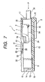
- Fig. 2 is a cross-sectional view of a connector housing;
- Fig. 3 is a cross-sectional view taken along the line III-III of Fig. 2;
- Fig. 4 is an enlarged perspective view of a lance;
- Fig. 5 is a perspective view of a terminal as seen obliquely from the upper side;
- Fig. 6 is a perspective view of the terminal as seen obliquely from the lower side;
- Fig. 7 is a cross-sectional view of the connector, showing a condition when the terminal is inserted;
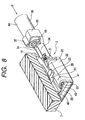
- Fig. 8 is an enlarged, perspective view of an important portion, showing a condition when the terminal is inserted;
- Fig. 9 is a cross-sectional view of the connector of Figs. 7 and 8 as seen from the front side of the terminal;
- Fig. 10 is a cross-sectional view of the connector of Fig. 1 as seen from the front side of the terminal; and
- Fig. 11 is a cross-sectional view of the connector, showing the inspection by a connector inspecting instrument when the terminal is in a half-inserted condition.
-
- In Fig. 1, a
connector 1, used for connecting vehicle's wire harnesses or the like together, comprises aconnector housing 2 made of a synthetic resin, and a plurality of terminals 3 (only one of which is shown) received in theconnector housing 2. Theconnector 1 is of such a construction that the amount of displacement of thelance 5, formed within a terminal receiving chamber 4 (formed in the connector housing 2) for receiving theterminal 3, is increased and stabilized, so that the detection of a half-inserted condition by a connector inspecting instrument 51 (described later; see Fig. 11) can be effected positively. - The above elements will now be described in detail.
- The
connector housing 2 is formed into a rectangular box-shape, and has the plurality of (for example, corresponding in number to the terminals 3) terminal receiving chambers 4 (only one of which is shown), each of theterminal receiving chamber 4 extending through theconnector housing 2 from a front side thereof to a rear side thereof. - The
terminal receiving chamber 4 defines a space of a rectangular parallelepiped shape for receiving the terminal 3 (see Fig. 1), and thelance 5 for retaining the completely-received terminal 3 (see Fig. 1) is formed integrally on anupper wall 7 of theterminal receiving chamber 4. An elastic displacement-allowingspace 8 for thelance 5 is formed in theupper wall 7. The elastic displacement-allowingspace 8 is provided for allowing the elastic deformation of thelance 5. - A
lower wall 9 of theterminal receiving chamber 4, disposed in opposed relation to theupper wall 7, is formed into a flat surface, and a base end portion 31 (described later; see Fig. 6) of theterminal 3 can be disposed in sliding contact with thislower wall 9. Aleft wall 10 and a right wall 11, disposed perpendicularly to the upper andlower walls upper wall 7 and thelower wall 9 serve as partition walls for vertically-adjacent (upper and lower) terminal receiving chambers 4 (not shown) or as an upper wall (not shown) and alower wall 12 of theconnector housing 2, respectively. - The
terminal receiving chamber 4 communicates with aconnection port 14 and a detectionpin insertion port 15, formed in afront wall 13 of theconnector housing 2, and also communicates with aterminal insertion port 17 open to arear end surface 16 of theconnector housing 2. - The
connection port 14 has a rectangular shape so as to receive a mating male terminal (not shown). A contactpin insertion port 18 for receiving an electrical contact pin 53 (described later; see Fig. 11) is continuous with theconnection port 14. - The contact
pin insertion port 18 is formed in opposed relation to the detectionpin insertion port 15, with theconnection port 14 disposed between the twoports terminal receiving chamber 4 through the contactpin insertion port 18. - The detection
pin insertion port 15 is disposed closer to theupper wall 7 than theconnection port 14 is, and a lance displacement detection pin 54 (described later; see Fig. 11) can be inserted into (and removed from) theterminal receiving chamber 4 through the detectionpin insertion port 15. The detectionpin insertion port 15 communicates with a central portion of theconnection port 14. - The upward-downward direction is the upward-downward direction in Fig. 2, and the forward-rearward direction is the left-right direction in Fig. 2. The right-left direction is the direction perpendicular to the sheet of Fig. 2, and corresponds to the width direction of the terminal receiving chamber.
- As shown in Figs. 2 to 4, the
lance 5 is an arm-like retaining member extending from a generally central portion of the upper wall 7 (in the forward-rearward direction) in a direction P (see Fig. 7) of insertion of the terminal 3 (see Fig. 1). When the terminal 3 (see Fig. 1) is completely received in theterminal receiving chamber 4, thelance 5 prevents the terminal 3 (see Fig. 1) from moving in a withdrawing direction (not shown) opposite to the inserting direction P (see Fig. 7). - More specifically, the
lance 5 includes aproximal end portion 19, anintermediate portion 20, a retainingprojection portion 21, adistal end portion 22, and twoprojections distal end portion 22 of thelance 5 is bent (elastically deformed) toward theupper wall 7, and the retainingprojection portion 21 and the twoprojections - The
proximal end portion 19 is continuous with the generally-central portion of theupper wall 7 in the forward-rearward direction, and theintermediate portion 20 of the same width extends from a distal end of theproximal end portion 19. Theintermediate portion 20 is in the form of a flattened bar or a plate-like piece. Theintermediate portion 20 extends downwardly obliquely from theproximal end portion 19, and arib 24, having a right-angled triangular shape (when viewed in the right-left direction) is formed integrally on a central portion of that surface of theintermediate portion 20 facing thelower wall 9. - A slanting side of the
rib 24 is formed integrally on that surface of theintermediate portion 20, facing thelower wall 9, and the other two sides extend in the upward-downward direction and the forward-rearward direction, respectively. - The
distal end portion 22 is formed on the distal end of theintermediate portion 20, and the retainingprojection portion 21 and the twoprojections intermediate portion 20. The distal end of theintermediate portion 20 is formed into a surface disposed in the upward-downward direction. - The retaining
projection portion 21 is formed on that surface of theintermediate portion 20, facing thelower wall 9, at a corner portion of the distal end thereof. The retainingprojection portion 21 has a retainingsurface 25 formed at the distal end of theintermediate portion 20, and this retainingsurface 25 can engage the terminal 3 (see Fig. 1). - The retaining
projection portion 21 has a right-angled triangular shape when viewed in the right-left direction (The directions of three sides of thisportion 21 are the same as the directions of the three sides of therib 24, respectively). This retainingprojection portion 21 has a trapezoidal shape (its upper side is close to the central portion of theintermediate portion 20, and its lower side coincides with the width of the intermediate portion 20) when viewed from that side where thelower wall 9 is disposed. - The
distal end portion 22 is formed on and projects from that portion of the distal end of theintermediate portion 20 disposed close to theupper wall 7. Thedistal end portion 22 is formed into a trapezoidal shape narrowing progressively toward thelower wall 9. Slanting sides of this trapezoidal shape (that is, slanting surfaces of the distal end portion 22) generally conform in inclination to inner slanting surfaces 40 and 40 (see Fig. 5) ofresilient curl portions 32 and 32 (described later). - When the
lance 5 is elastically deformed, thedistal end portion 22 can be positively disposed in the elastic deformation-allowingspace 8. - The
projections intermediate portion 20 facing theleft wall 10 and the right wall 11, respectively. Theprojections terminal receiving chamber 4. Each of theprojections connector housing 2 toward the rear end of the connector housing 2). - Each of the
projections surface 26, disposed parallel to that surface of theintermediate portion 20 facing thelower wall 9, a slidingsurface 27, disposed parallel to thelower wall 9, and a retainingsurface 28 disposed in a plane in which the retainingsurface 25 lies. - The tapering surfaces 26 and 26, the sliding
surfaces resilient curl portions 32 and 32 (described later; see Fig. 5) can abut against the tapering surfaces 26 and 26, respectively. Apexes 41 and 41 (see Fig. 5) of theresilient curl portions 32 and 32 (described later; see Fig. 5) can be brought into sliding contact with the slidingsurfaces resilient curl portions 32 and 32 (described later; see Fig. 5) can engage the retainingportions - As shown in Figs. 5 and 6, the
terminal 3 is of the female type, and is formed by pressing an electrically-conductive metal sheet a plurality of times. Theterminal 3 includes the spatula-likebase plate portion 31, the pair ofresilient curl portions contact piece portions conductor clamping portions sheath clamping portions portions 32 and theportions 33 are formed at a front portion of thebase plate portion 31 whereas theportions 34 and theportions 35 are formed at a rear portion of thebase plate portion 31. - The front portion of this terminal serves as an electrical contact portion for the mating male terminal (not shown), and the rear portion thereof serves as a wire connection portion for a
wire 36, for example, of a vehicle's wire harness. - An electrical contact
convex portion 37 is formed on the front portion of thebase plate portion 31 by embossing, and bulges toward theresilient curl portions convex portion 37 cooperates with the electricalcontact piece portions convex portion 37 has a taperingsurface 38 formed over an entire periphery thereof, and a front portion of the taperingsurface 38 can guide the mating male terminal (not shown) into a predetermined position. - The
resilient curl portions base plate portion 31, and eachcurl portion 32 has a piece-like shape having a large width in a direction of extending of thebase plate portion 31. This piece-like portion, forming thecurl portion 32, is inwardly bent into a generally mountain-like cross-sectional shape. Anouter slanting surface 39 of eachresilient curl portion 32 is defined by an abruptly-slanting surface (because of the generally mountain-like cross-sectional shape) disposed almost perpendicularly to thebase plate portion 32. On the other hand, theinner slanting surface 40 of each curl portion is defined by a gently-slanting surface much more smaller in inclination than theouter slanting surface 39. - The
projections 23 and 23 (see Fig. 4) of the lance 5 (see Fig. 5) can be brought into sliding contact with theapexes resilient curl portions resilient curl portions resilient curl portion 32 from thebase plate portion 31 to the apex 41 thereof is not changed. - Each of the electrical
contact piece portions base plate portion 31. The distal end portion of eachresilient curl portion 32 is bent obliquely upwardly at a small angle to form the electricalcontact piece portion 33. Front ends 42 and 42 of the electricalcontact piece portions contact piece portions resilient curl portions - The
conductor clamping portions base plate portion 31, and serve to hold a conductor 45 (exposed by removing a sheath 44) of thewire 36 at an end portion thereof. Theconductor clamping portions conductor 45. -
Frame portions base plate portion 31, and eachframe portion 46 extends between theconductor clamping portion 34 and theresilient curl portion 32. - The
sheath clamping portions sheath 44 of thewire 36, and have a rectangular shape, and are larger in length than theconductor clamping portions sheath clamping portions base plate portion 31. Thesheath clamping portions sheath 44, and theconductor 45, covered with thesheath 44, is compressed through thesheath 44. - In the above construction, for assembling the
connector 1, theterminals 3 are inserted respectively into theterminal receiving chambers 4. - When the
terminal 3 is inserted into theterminal receiving chamber 4 as shown in Figs. 7 to 9, thelance 5 within theterminal receiving chamber 4 is elastically deformed by theterminal 3. More specifically, theresilient curl portions terminal 3 abut respectively against the tapering surfaces 26 and 26 of theprojections lance 5 to press the tapering surfaces 26 and 26, so that thelance 5 is elastically deformed in such a manner that thedistal end portion 22 moves toward theupper wall 7. Then, thelance 5 is continued to be elastically deformed by theterminal 3 until theprojections apexes resilient curl portions - In this condition, when the
terminal 3 is further inserted, theprojections apexes resilient curl portions apexes resilient curl portions projections lance 5 is restored into its original condition because of its restoring force, and engages the rear ends 47 and 47 of theresilient curl portions projections - As a result, the
terminal 3 is completely received in theterminal receiving chamber 4. Thelance 5 is thus engaged with theterminal 3, thereby preventing the terminal 3 from withdrawal from theterminal receiving chamber 4. - When all of the
terminals 3 are received in the correspondingterminal receiving chambers 4, respectively, the assemblage of theconnector 1 is completed. - The completed
connector 1 is inspected by theconnector inspecting instrument 51 so as to determine whether or not any of theterminals 3 is in a half-inserted condition. - In Fig. 11, the
connector inspecting instrument 51 includes a plurality of inspection pin portions 52 (corresponding in number to theterminals 3 and also to the terminal receiving chambers 4). Theinspection pin portion 52 has theelectrical contact pin 53 and the lancedisplacement detection pin 54. Theelectrical contact pin 53, when inserted into theterminal receiving chamber 4, contacts thebase plate portion 31 of theterminal 3, and the lancedisplacement detection pin 54 can abut against thelance 5 in a half-inserted condition of the terminal. - The
electrical contact pin 53 is shorter than the lancedisplacement detection pin 54. Theelectrical contact pin 53 and the lancedisplacement detection pin 54 are electrically disconnected from each other. - In this embodiment, a half-inserted condition of the
terminal 3 can be detected by the use of theconnector inspecting instrument 51 of a known construction (disclosed, for example, in Unexamined Japanese Patent Publication No. Hei. 7-113836 earlier filed by the Applicant of the present application). Therefore, the showing of this connector inspecting instrument is simplified in the drawings. - In Fig. 11, when the operation for inserting the
terminal 3 is finished, with theterminal 3 held in a half-inserted condition, thelance 5 is kept stranded on theapexes resilient curl portions projections displacement detection pin 54 is inserted into theterminal receiving chamber 4 along theupper wall 7, this lancedisplacement detection pin 54 is brought into abutting engagement with thelance 5, thus detecting the half-inserted condition. Namely, when the lancedisplacement detection pin 54 abuts against thelance 5, theelectrical contact pin 54 can not contact theterminal 3, and therefore can not be electrically connected to theterminal 3, so that the half-fitted condition is detected. - On the other hand, when the
terminal 3 is completely received in theterminal receiving chamber 4, the lancedisplacement detection pin 54 can be inserted deep (into a position near to theproximal end portion 19 of the lance 5). Therefore, theelectrical contact pin 54 can contact theterminal 3 to be electrically connected thereto, and therefore it is judged that theterminal 3 is completely received in theterminal receiving chamber 4. - As described above with reference to Figs. 1 to 11, the
lance 5 has the twoprojections apexes resilient curl portions terminal 3, and therefore, in a half-inserted condition of theterminal 3, thelance 5 is much displaced from its initial condition. And besides, the height of the terminal 3 from thebase plate portion 31 to theapexes resilient curl portions lance 5 is always stable. Therefore, the detection by theconnector inspecting instrument 51 can be positively effected. - Various modifications can be made without departing from the scope of the present invention.
- Although not shown in the drawings, the connector can be of such a construction that the
terminal receiving chambers 4 are arranged in two (upper and lower) rows, or are juxtaposed in a row. - As described above, in the present invention, the connector comprises the terminals, and the connector housing having the terminal receiving chambers, and the lance, formed within the terminal receiving chamber, has the two projections for sliding contact respectively with the apexes of the resilient curl portions of the terminal. Therefore, the amount of displacement of the lance can be increased and stabilized.
- Namely, the lance is elastically deformed by the terminal until the two projections slide onto the apexes of the resilient curl portions, respectively, and therefore the amount of displacement of the lance in the engaged condition is large. Even if the inclination of the inner slanting surfaces of the resilient curl portions is changed when adjusting the terminal inserting force and the contact load, the height of the terminal from the base plate portion to the apexes of the resilient curl portions is not changed, and therefore the amount of displacement of the lance is always stable.
- If the terminal inserting operation is finished, with the terminal held in a half-inserted condition, the lance is kept stranded on the apexes of the resilient curl portions through the two projections, so that the amount of displacement of the lance is large. In the subsequent inspecting process, the half-inserted condition can be positively detected on the basis of the position of the distal end portion of the lance.
- Therefore, there is achieved an advantageous effect that there can be provided the connector in which the amount of displacement of the lance is stable, and the detection by the connector inspecting instruction can be positively effected.
- In the present invention, each of the projections has the surface disposed in a plane in which the retaining surface of the retaining projection portion lies. Therefore, the terminal can be retained by the retaining projection portion and the two projections.
- Therefore, in addition to the above effect, there is achieved an advantageous effect that the retaining force for retaining the terminal is enhanced. Therefore, the better connector can be provided.
- In the present invention, each of the projections is decreasing in thickness progressively in the withdrawing direction opposite to the terminal inserting direction, thereby forming the tapering surface. Therefore, although the projections are formed on the lance, these projections will not affect the terminal inserting operation.
- Therefore, the above advantageous effects of the present invention can be achieved, while maintaining the operation efficiency as achieved with the related construction.
Claims (7)
- A connector (1), comprising:when the terminal (3) is inserted into the terminal receiving chamber (4), the projections (23) are respectively brought into sliding contact with apexes (41) of the resilient curl portions (32).a connector housing (2) including a terminal receiving chamber (4);a metal terminal (3) insertable into the terminal receiving chamber (4), the terminal (3) including a base plate portion, a wire connecting portion formed on the base plate portion, and an electrical contact portion having resilient curl portions (32) which extend from opposite side edges of the base plate portion and are inwardly bent to form curls thereof;a lance (5) formed in the terminal receiving chamber (4), the lance having a distal end portion (22) which extends in an inserting direction of the terminal;a retaining projection portion (21) formed on the lance (5), the retaining projection portion (21) retaining the terminal (3) in a complete insertion state thereof to be prevented from moving in a withdrawing direction opposite to the inserting direction; andat least two projections (23) integrally formed on the lance (5), the projections (23) projecting in a width direction of the terminal receiving chamber (4) which is perpendicular to the inserting direction of the terminal, characterised in that
- The connector (1) of claim 1, wherein the lance (5) is formed in a cantilever manner with respect to the connector housing (2) to be elastically deformable.
- The connector (1) of claim 1, wherein each of the resilient curl portions (32) has a generally mountain-like shape in a cross section thereof.
- The connector (1) of claim 1, wherein the retaining projection portion (21) is formed on a portion of the lance (5) near to the distal end portion (22) thereof, the retaining projection portion (21) engages the terminal (3) to be retained in the terminal receiving chamber (4).
- The connector (1) of claim 1, wherein the curl portions (32) are respectively formed integrally with the opposite side edges of the base plate portion of the terminal (3).
- The connector (1) of claim 1, wherein each of the projections (23) has a surface disposed in a plane in which a retaining surface of the retaining projection portion lies.
- The connector (1) of claim 1 or claim 6, wherein each of the projections (23) has a tapering surface (26) so formed that each of the projections (23) is decreased in thickness progressively in the withdrawing direction of the terminal (3) opposite to the inserting direction.
Applications Claiming Priority (2)
| Application Number | Priority Date | Filing Date | Title |
|---|---|---|---|
| JP34849499A JP3601772B2 (en) | 1999-12-08 | 1999-12-08 | connector |
| JP34849499 | 1999-12-08 |
Publications (2)
| Publication Number | Publication Date |
|---|---|
| EP1107380A1 EP1107380A1 (en) | 2001-06-13 |
| EP1107380B1 true EP1107380B1 (en) | 2004-05-12 |
Family
ID=18397397
Family Applications (1)
| Application Number | Title | Priority Date | Filing Date |
|---|---|---|---|
| EP00310775A Expired - Lifetime EP1107380B1 (en) | 1999-12-08 | 2000-12-04 | Connector |
Country Status (4)
| Country | Link |
|---|---|
| US (1) | US6626701B2 (en) |
| EP (1) | EP1107380B1 (en) |
| JP (1) | JP3601772B2 (en) |
| DE (1) | DE60010632T2 (en) |
Families Citing this family (21)
| Publication number | Priority date | Publication date | Assignee | Title |
|---|---|---|---|---|
| JP3969161B2 (en) * | 2002-04-05 | 2007-09-05 | 住友電装株式会社 | connector |
| DE10320665B4 (en) * | 2002-05-23 | 2008-11-13 | Sumitomo Wiring Systems, Ltd., Yokkaichi | Interconnects |
| EP1369959B1 (en) * | 2002-06-06 | 2007-10-24 | Sumitomo Wiring Systems, Ltd. | A connector, a disengagement jig and a method |
| JP2004296182A (en) * | 2003-03-26 | 2004-10-21 | Sumitomo Wiring Syst Ltd | Connector |
| JP4304478B2 (en) * | 2004-03-03 | 2009-07-29 | 住友電装株式会社 | connector |
| KR100826842B1 (en) | 2007-02-26 | 2008-05-02 | 한국단자공업 주식회사 | Connector assembly |
| KR200448119Y1 (en) | 2007-11-21 | 2010-03-18 | 한국단자공업 주식회사 | Connector-housing |
| JP5161004B2 (en) * | 2008-08-27 | 2013-03-13 | 矢崎総業株式会社 | Connector housing and connector |
| JP5258667B2 (en) * | 2009-04-23 | 2013-08-07 | 矢崎総業株式会社 | Housing mold structure, housing molding method, and housing |
| JP5571976B2 (en) * | 2010-03-01 | 2014-08-13 | 住友電装株式会社 | connector |
| JP5586346B2 (en) * | 2010-07-02 | 2014-09-10 | 矢崎総業株式会社 | connector |
| JP5618667B2 (en) * | 2010-07-20 | 2014-11-05 | 矢崎総業株式会社 | Connector inspection system |
| JP5656121B2 (en) * | 2011-06-02 | 2015-01-21 | 住友電装株式会社 | connector |
| JP5933380B2 (en) * | 2012-07-25 | 2016-06-08 | 矢崎総業株式会社 | connector |
| JP6104064B2 (en) * | 2013-06-14 | 2017-03-29 | 矢崎総業株式会社 | connector |
| JP6448925B2 (en) * | 2014-06-20 | 2019-01-09 | 矢崎総業株式会社 | connector |
| US10892577B1 (en) * | 2019-07-10 | 2021-01-12 | Lear Corporation | Electric terminal connector assembly with a terminal lock |
| US11050181B2 (en) * | 2019-07-10 | 2021-06-29 | Lear Corporation | Electric terminal connector assembly with a terminal lock |
| JP7104103B2 (en) * | 2020-06-26 | 2022-07-20 | 矢崎総業株式会社 | connector |
| JP7424247B2 (en) * | 2020-08-26 | 2024-01-30 | 住友電装株式会社 | connector |
| CN114498131A (en) * | 2020-10-23 | 2022-05-13 | 泰科电子(上海)有限公司 | Connecting terminal and connecting assembly |
Family Cites Families (12)
| Publication number | Priority date | Publication date | Assignee | Title |
|---|---|---|---|---|
| US4448468A (en) * | 1982-07-09 | 1984-05-15 | Amp Incorporated | Receptacle terminal having latching feature |
| FR2584540B1 (en) * | 1985-07-04 | 1987-09-25 | Labinal | IMPROVEMENTS IN MOUNTING ELECTRICAL CONNECTION DEVICES |
| JP2519179Y2 (en) * | 1989-03-29 | 1996-12-04 | 矢崎総業株式会社 | Double locking structure for terminal fittings in electrical connectors |
| JPH056692U (en) * | 1991-07-01 | 1993-01-29 | 矢崎総業株式会社 | connector |
| JPH0633373A (en) | 1992-07-10 | 1994-02-08 | Yoshikazu Yamaguchi | Method for permanently setting wool product and hair |
| JP3029081B2 (en) | 1993-08-24 | 2000-04-04 | 矢崎総業株式会社 | Connector inspection tool |
| JP2986005B2 (en) * | 1993-12-28 | 1999-12-06 | 矢崎総業株式会社 | Reverse insertion prevention connector |
| JP3132706B2 (en) * | 1994-06-06 | 2001-02-05 | 矢崎総業株式会社 | Female terminal for connector |
| JPH087969A (en) * | 1994-06-17 | 1996-01-12 | Yazaki Corp | Connector housing |
| JP3107141B2 (en) * | 1995-06-23 | 2000-11-06 | 矢崎総業株式会社 | Connector terminal locking structure |
| JP3417769B2 (en) * | 1996-09-18 | 2003-06-16 | カルソニックカンセイ株式会社 | Connector with terminal lock |
| JP3397298B2 (en) * | 1998-08-20 | 2003-04-14 | 住友電装株式会社 | connector |
-
1999
- 1999-12-08 JP JP34849499A patent/JP3601772B2/en not_active Expired - Fee Related
-
2000
- 2000-12-04 DE DE60010632T patent/DE60010632T2/en not_active Expired - Fee Related
- 2000-12-04 EP EP00310775A patent/EP1107380B1/en not_active Expired - Lifetime
- 2000-12-08 US US09/731,976 patent/US6626701B2/en not_active Expired - Fee Related
Also Published As
| Publication number | Publication date |
|---|---|
| US20010003686A1 (en) | 2001-06-14 |
| DE60010632D1 (en) | 2004-06-17 |
| DE60010632T2 (en) | 2004-09-23 |
| US6626701B2 (en) | 2003-09-30 |
| JP2001167833A (en) | 2001-06-22 |
| EP1107380A1 (en) | 2001-06-13 |
| JP3601772B2 (en) | 2004-12-15 |
Similar Documents
| Publication | Publication Date | Title |
|---|---|---|
| EP1107380B1 (en) | Connector | |
| EP1104051B1 (en) | Connector | |
| US7144281B2 (en) | Female terminal fitting and a blank for a plurality of terminal fittings | |
| US6116939A (en) | Connector lock mechanism | |
| EP1560298B1 (en) | A divided connector and connector assembly | |
| EP1137118B1 (en) | A connector having at least one contact-pin inserting port for insertion of a conduction contact pin of a connector conduction-test tool | |
| US7563135B2 (en) | Connector | |
| US7766697B2 (en) | Connector | |
| EP0549958A2 (en) | Female electrical terminal with improved contact force | |
| US7001214B2 (en) | Connector | |
| JP3101203B2 (en) | Electrical connector with retainer | |
| US5437567A (en) | Female electrical terminal | |
| JPH05258792A (en) | Male electric terminal having excessive stress preventing means | |
| CN113851880B (en) | Connector with a plurality of connectors | |
| JP3635629B2 (en) | connector | |
| US6629864B2 (en) | Electrical contact for plug-in connector | |
| JP3717057B2 (en) | Connector side spacer structure | |
| US6589080B2 (en) | Terminal fitting and a connector | |
| EP0660446B1 (en) | Electrical connector with flexible terminal latch means and terminal position assurance device | |
| JP3601773B2 (en) | Terminal | |
| JPH0822866A (en) | Connector | |
| JPH0658568U (en) | connector |
Legal Events
| Date | Code | Title | Description |
|---|---|---|---|
| PUAI | Public reference made under article 153(3) epc to a published international application that has entered the european phase |
Free format text: ORIGINAL CODE: 0009012 |
|
| AK | Designated contracting states |
Kind code of ref document: A1 Designated state(s): DE FR GB |
|
| AX | Request for extension of the european patent |
Free format text: AL;LT;LV;MK;RO;SI |
|
| 17P | Request for examination filed |
Effective date: 20011116 |
|
| AKX | Designation fees paid |
Free format text: DE FR GB |
|
| 17Q | First examination report despatched |
Effective date: 20030508 |
|
| GRAP | Despatch of communication of intention to grant a patent |
Free format text: ORIGINAL CODE: EPIDOSNIGR1 |
|
| GRAS | Grant fee paid |
Free format text: ORIGINAL CODE: EPIDOSNIGR3 |
|
| GRAA | (expected) grant |
Free format text: ORIGINAL CODE: 0009210 |
|
| AK | Designated contracting states |
Kind code of ref document: B1 Designated state(s): DE FR GB |
|
| REG | Reference to a national code |
Ref country code: GB Ref legal event code: FG4D |
|
| REF | Corresponds to: |
Ref document number: 60010632 Country of ref document: DE Date of ref document: 20040617 Kind code of ref document: P |
|
| ET | Fr: translation filed | ||
| PLBE | No opposition filed within time limit |
Free format text: ORIGINAL CODE: 0009261 |
|
| STAA | Information on the status of an ep patent application or granted ep patent |
Free format text: STATUS: NO OPPOSITION FILED WITHIN TIME LIMIT |
|
| 26N | No opposition filed |
Effective date: 20050215 |
|
| PGFP | Annual fee paid to national office [announced via postgrant information from national office to epo] |
Ref country code: FR Payment date: 20081212 Year of fee payment: 9 |
|
| PGFP | Annual fee paid to national office [announced via postgrant information from national office to epo] |
Ref country code: DE Payment date: 20081127 Year of fee payment: 9 |
|
| PGFP | Annual fee paid to national office [announced via postgrant information from national office to epo] |
Ref country code: GB Payment date: 20081203 Year of fee payment: 9 |
|
| GBPC | Gb: european patent ceased through non-payment of renewal fee |
Effective date: 20091204 |
|
| REG | Reference to a national code |
Ref country code: FR Ref legal event code: ST Effective date: 20100831 |
|
| PG25 | Lapsed in a contracting state [announced via postgrant information from national office to epo] |
Ref country code: FR Free format text: LAPSE BECAUSE OF NON-PAYMENT OF DUE FEES Effective date: 20091231 |
|
| PG25 | Lapsed in a contracting state [announced via postgrant information from national office to epo] |
Ref country code: DE Free format text: LAPSE BECAUSE OF NON-PAYMENT OF DUE FEES Effective date: 20100701 |
|
| PG25 | Lapsed in a contracting state [announced via postgrant information from national office to epo] |
Ref country code: GB Free format text: LAPSE BECAUSE OF NON-PAYMENT OF DUE FEES Effective date: 20091204 |