EP1107356A2 - Device for wireless reception of radio signals - Google Patents
Device for wireless reception of radio signals Download PDFInfo
- Publication number
- EP1107356A2 EP1107356A2 EP00403432A EP00403432A EP1107356A2 EP 1107356 A2 EP1107356 A2 EP 1107356A2 EP 00403432 A EP00403432 A EP 00403432A EP 00403432 A EP00403432 A EP 00403432A EP 1107356 A2 EP1107356 A2 EP 1107356A2
- Authority
- EP
- European Patent Office
- Prior art keywords
- antenna
- field strength
- mid
- reception field
- reception
- Prior art date
- Legal status (The legal status is an assumption and is not a legal conclusion. Google has not performed a legal analysis and makes no representation as to the accuracy of the status listed.)
- Withdrawn
Links
Images


Classifications
-
- H—ELECTRICITY
- H01—ELECTRIC ELEMENTS
- H01Q—ANTENNAS, i.e. RADIO AERIALS
- H01Q3/00—Arrangements for changing or varying the orientation or the shape of the directional pattern of the waves radiated from an antenna or antenna system
- H01Q3/02—Arrangements for changing or varying the orientation or the shape of the directional pattern of the waves radiated from an antenna or antenna system using mechanical movement of antenna or antenna system as a whole
- H01Q3/08—Arrangements for changing or varying the orientation or the shape of the directional pattern of the waves radiated from an antenna or antenna system using mechanical movement of antenna or antenna system as a whole for varying two co-ordinates of the orientation
-
- H—ELECTRICITY
- H01—ELECTRIC ELEMENTS
- H01Q—ANTENNAS, i.e. RADIO AERIALS
- H01Q1/00—Details of, or arrangements associated with, antennas
- H01Q1/12—Supports; Mounting means
- H01Q1/125—Means for positioning
- H01Q1/1257—Means for positioning using the received signal strength
-
- H—ELECTRICITY
- H04—ELECTRIC COMMUNICATION TECHNIQUE
- H04B—TRANSMISSION
- H04B17/00—Monitoring; Testing
- H04B17/20—Monitoring; Testing of receivers
- H04B17/27—Monitoring; Testing of receivers for locating or positioning the transmitter
-
- H—ELECTRICITY
- H04—ELECTRIC COMMUNICATION TECHNIQUE
- H04B—TRANSMISSION
- H04B17/00—Monitoring; Testing
- H04B17/30—Monitoring; Testing of propagation channels
- H04B17/309—Measuring or estimating channel quality parameters
- H04B17/318—Received signal strength
Definitions
- the invention relates to a device for wireless reception of radio signals, in particular a device which is linked to a wireless network.
- the invention is based on a device which is equipped with an antenna for receiving the radio signals from the network, with the antenna signal being emitted to a tuner, and finally being fed to a signal evaluation circuit.
- the signal evaluation circuit determines, inter alia, the reception field strength.
- a problem which frequently occurs when setting up networks which are not based on wires is that the field strength distribution in a room is highly inhomogeneous due to reflections on walls, ceilings and objects. This can lead to the signal to be received being very severely attenuated at the location of the receiving antenna while, at a point only a few centimetres away, it can be received virtually without any attenuation.
- Such networks may be used, for example, for networking of consumer electronics devices.
- both antennas are located at points at which the field strength is too low at a specific time. For example, it is possible to switch from a first antenna, which is currently receiving a signal that is still acceptable, to the second antenna, whose wanted signal is even poorer. For this reason, switching from one antenna to the other can take place only when appropriate aids have already determined that reception with the other antenna is better. It is thus impossible to switch antennas during regular reception operation, even if this would be desirable due to rapid changes in the reception field strength which are caused, for example, by people moving in the room.
- the object of the invention is to provide a device whose reception quality is better than that from the prior art. This object is achieved by a device according to Claim 1.
- the drive unit can expediently be provided with guidance means which allow the antenna to move in a plane.
- the guidance means can be in the form of a rotating table, for example a circular ring.
- the circular ring can be provided on its outer circumferential face with a tooth system in which a drive pinion of a drive motor engages.
- the guidance means may be in the form of guide rails which can move in the translational direction. It is particularly expedient for the translation directions of the guide rails to be oriented at right angles to one another. Using such a device it is possible for the antenna to carry out any desired movements within the movement range of the guide rails. It is particularly expedient for the guide rails to be driven via a spindle drive.
- the antenna signal may be advantageous to transmit the antenna signal, by means of a transmitter, from the moving antenna to a fixed position circuit part.
- a further object of the invention is to specify a method in order to readjust a moving antenna to a position where the reception field strength is greater. This object is achieved by a method according to Claim 10.
- FIG. 1 shows the results of field strength measurements in an area with a size of 25 x 50 cm in a room, that is to say the grid shown in Figure 1 has a grid size of approximately 3 cm.
- Bright areas, which are denoted by the reference symbol 2 in Figure 1 indicate regions where the field strength is high, while dark areas, which are denoted by the reference symbol 3, indicate regions where the field strength is low.
- the relationship between the attenuation of the signal and the individual grey levels can be see from the bar in the lower part of Figure 1.
- Figure 1 clearly shows that there are areas in which the signal can be received with virtually no attenuation, while the signal is severely attenuated in other areas.
- the areas where the attenuation is severe form contiguous strips, which include areas where the attenuation is low.
- the measurements were carried out in the 2.4 Gigahertz frequency band, that is to say the intervals between these observed strips correspond approximately to the actual wavelength of the signal.
- This figure shows that it is possible, when using a device which is equipped with two switchable antennas, for both antennas to be in an area where signals can be received only weakly.
- the figure clearly shows that there is a high probability of a region with a high reception field strength being located in the immediate vicinity of a region with only a low reception field strength. The invention makes use of this fact.
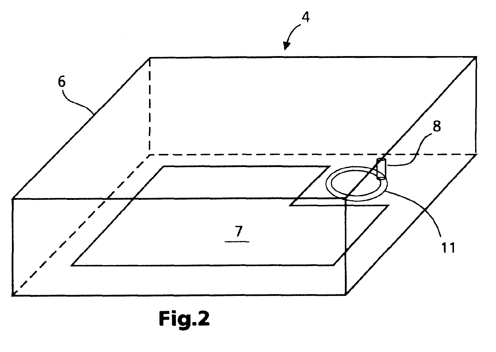
- FIG. 2 illustrates, schematically, a device according to the invention which is denoted, overall, by the reference symbol 4.
- the device 4 is surrounded by a housing 6 which accommodates a main board 7.
- a moving antenna 8 is also arranged, on a moving base, in the housing 6.
- the adjustment movement of the antenna does not need to be greater than approximately one wavelength of the radio signal, that is to say, in networks which operate in the gigahertz band, it is sufficient for the adjustment movement to be approximately a few centimetres.
- the antenna it must be possible for the antenna to move in at least two different directions since any given movement may be composed of two translation movements whose movement directions are oriented at right angles to one another.
- the antenna is moved along a circular arc.
- FIG 3a shows a plan view from above of a first exemplary embodiment of a moving antenna 8.
- the antenna 8 is arranged on an annular rotating table 11 whose outer circumference 12 is toothed.
- a detail shows an enlargement of the tooth system 13, in which a drive pinion 14 of a motor 16 engages.
- Figure 3b shows a view of the arrangement from the side.
- the rotating table 11 is mounted on a bearing 17 such that it can rotate, so that the rotating table 11 can be caused to revolve by the motor 16.
- the bearing 17 is connected by holders 18 to a baseplate 19 on which the motor 16 is also fitted.
- the antenna is connected via a waveguide 21 to a transmitter 22, which transmits the received antenna signal without wires from the rotating table 11 to the stationary baseplate 19. This ensures that no cable becomes unscrewed if, due to particular circumstances, the rotating table 11 were to move in only one rotation sense.
- the rotating table 11 may have a diameter of 10 cm to 15 cm.
- FIG 4a shows a further exemplary embodiment of the invention, viewed from above.
- Two guide rails 32 and 33 which can move in the translational direction, are arranged in a frame 31.
- the antenna 8 is mounted on an antenna holder 34, which is mounted by means of four guide pins 36 on the guide rails 32 and 33 such that it can be moved longitudinally in each case. Since the guide rails 32, 33 are arranged in a cruciform pattern, the antenna holder 34 remains fixed at the point where the guide rails cross.
- a centre pin 37 projects under the guide rails in the centre of the antenna holder 34.
- the centre pin 37 engages in a receptacle 38 in a pivoting arm 39.
- the pivoting arm can be pivoted by means of a motor 41.
- the guide rails 32, 33 are mounted such that they can slide in the frame 31 so that the antenna carries out a rotating movement along the circular path, which is indicated by the line 42, when the pivoting arm 39 pivots.
- the antenna 8 itself is held on the antenna holder 34 such that it can rotate, and it is thus possible for the antenna to be connected directly by means of an antenna cable 43 without there being any risk of the antenna cable becoming twisted, for example during continued circular movement of the antenna.
- the antenna cable is expediently routed upwards, so that it cannot be trapped in the guide rails or in the pivoting arm.
- the guide rails are provided at at least one end with threaded sleeves in which a threaded spindle, which can rotate, engages. Rotation of the threaded spindles causes the guide rails to move in the translational direction, so that the antenna is in turn moved on the circular path shown in Figure 4a.
- the guide rails are driven by drive elements composed of so-called memory metals, whose length is variable to a considerable extent.
- the increase in length is controlled, for example, by means of a temperature change, which is caused by a current flow in the memory metal.
- the way in which the physical position of the antenna is changed is irrelevant to the invention itself. It is also irrelevant whether the movement of the antenna actually follows a circular path. However, for the reasons mentioned initially, it is expedient for the movement not to be a straight line.
- FIG. 5 shows a block diagram of a circuit which evaluates the reception field strength and controls the movement of the antenna as a function of this.
- the signal from the antenna 8 is emitted to a tuner 43 and is fed to a demodulator 44, which emits the said signal to a signal processing circuit, which is not shown.
- the output signal from the tuner is rectified and is converted in an A/D converter 46 to a digital value which describes the present amplitude of the tuner signal.
- This digital value is evaluated in a microprocessor 47 by means of a specific program, which will be described in the following text.
- the microprocessor emits control commands to a driver circuit 48, which drives the motor 41 as appropriate.
- the antenna When the device is being operated, the antenna is continually moved through short distances away from its present position, which is referred to in the following text as the mid-position.
- the antenna 8 carries out a small-amplitude oscillation about the mid-position, with the deflection being, for example, ⁇ 15°.
- This oscillatory movement is controlled by the microprocessor 47.
- the microprocessor 47 evaluates the reception field strength at the end points and in the centre of this oscillatory movement. The respective reception field strengths from these measured values are compared in order to calculate whether the mid-position of the antenna is located at a local minimum, at a maximum or in a transitional region.
- the antenna is moved in the direction of the maximum reception field strength.
- the mid-position of the oscillation is shifted such that it coincides with that inversion point at which the maximum reception field strength was previously measured.
- the magnitude of the adjustment movement may also be greater or smaller. If the maximum reception field strength occurs at the mid-position, the location of the mid-position is not changed. This process is continually repeated during operation of the device since the areas of high and low reception field strength are generally not static in a room. As soon as the reflection conditions in the room change, as is caused, for example, by people moving, the field strength distribution also changes.
- the control system described above therefore has to operate sufficiently fast to be able to compensate even for fluctuations of this type.
- This method can advantageously be carried out even during reception operation, since there is no need to worry that the reception field strength will suddenly fall to such an extent that it is no longer possible to receive a wanted signal.
- Two moving antennas are provided in a further exemplary embodiment of the invention.
- the other antenna carries out the oscillatory movement described above, until the antenna has reached a local reception field strength maximum, that is to say the location of the mid-position is no longer changed. If the reception field strength of the second antenna becomes greater than that of the first, then the microprocessor switches from the first antenna to the second.
- This exemplary embodiment ensures that a more uniform reception field strength is available during reception operation.
- two antennas are arranged on one rotating table.
- a first antenna is held such that it can move with respect to the rotating table so that, even when the rotating table is stationary, this antenna can carry out an oscillatory movement, in the form of a circular arc, in the circumferential direction.
- the second antenna changes its position only when the rotating table is rotated. The position of the antennas is in this case selected such that the second antenna and the mid-point of the oscillation of the first antenna are in the same radial position.
- the second antenna is always used to receive the wanted signal, while the first antenna is used to determine the reception conditions in the immediate vicinity of the second antenna. If this leads to the result that the reception conditions are better in a different rotation position of the rotating table, the rotating table is readjusted.
- This arrangement has the advantage that the reception conditions for the second antenna change only slowly, and that the received signal does not contain any discontinuities resulting from switching between two antennas.
Landscapes
- Engineering & Computer Science (AREA)
- Physics & Mathematics (AREA)
- Electromagnetism (AREA)
- Computer Networks & Wireless Communication (AREA)
- Signal Processing (AREA)
- Quality & Reliability (AREA)
- Variable-Direction Aerials And Aerial Arrays (AREA)
- Support Of Aerials (AREA)
- Radio Transmission System (AREA)
- Monitoring And Testing Of Transmission In General (AREA)
Abstract
Description
- Figure 1
- shows the field strength distribution in a room,
- Figure 2
- shows the arrangement of a moving antenna in a device.
- Figures 3a and 3b
- show an exemplary embodiment of a moving antenna, viewed from above and from the side,
- Figures 4a and 4b
- show a further exemplary embodiment of a moving antenna, viewed from above and from the side, and
- Figure 5
- shows a block diagram of a circuit which evaluates the reception field strength and controls the movement of the antenna.
Claims (10)
- Device for wireless reception of radio signals having an antenna and a signal evaluation circuit which determines the reception field strength, characterized in that the antenna (8) is designed to be movable, in that a drive unit moves the antenna from rest position during reception operation, and in that, while this is taking place, a signal evaluation circuit evaluates the reception field strength and emits a control signal to the drive unit (14; 41, 39), and the drive unit changes the physical location of the mid-position of the antenna in the sense of increasing the reception field strength.
- Device according to Claim 1, characterized in that the drive unit comprises guidance means (11; 32, 33) which allow the antenna to move in a plane.
- Device according to Claim 2, characterized in that the guidance means are in the form of a rotating table (11).
- Device according to Claim 3, characterized in that the rotating table is in the form of a circular ring.
- Device according to Claim 4, characterized in that the circular ring is provided on a circumferential face (12) with a tooth system (13) in which a drive pinion (14) of a drive motor (14) engages.
- Device according to Claim 2, characterized in that the guidance means comprise guide rails (32, 33) which can move in the translational direction.
- Device according to Claim 6, characterized in that the guidance means are formed from two guide rails whose translation directions are oriented at right angles to one another.
- Device according to Claim 2, characterized in that a transmitter (22) is connected to the antenna and is suitable for transmitting the antenna signal from the moving guidance means to the stationary part of the device without wires.
- Device according to Claim 1, characterized in that the said device is equipped with a second moving antenna.
- Method for readjusting a moving antenna to a position in which the reception field strength is greater, with the method comprising the following steps:a) the antenna is moved from a mid-position in the form of an oscillation,b) the reception field strength is measured at the mid-position and at the inversion points of the oscillation,c) the measured reception field strengths are compared with one another,d) if the measured reception field strength at one inversion point is greater than at the mid-position, a new mid-position is selected which is closer to the said inversion point than the original mid-position, ande) if the measured reception field strength at the mid-position is greater than at the inversion points, the location of the mid-position is not changed.
Applications Claiming Priority (2)
| Application Number | Priority Date | Filing Date | Title |
|---|---|---|---|
| DE19959715A DE19959715A1 (en) | 1999-12-10 | 1999-12-10 | Device for the wireless reception of radio signals |
| DE19959715 | 1999-12-10 |
Publications (2)
| Publication Number | Publication Date |
|---|---|
| EP1107356A2 true EP1107356A2 (en) | 2001-06-13 |
| EP1107356A3 EP1107356A3 (en) | 2002-11-13 |
Family
ID=7932232
Family Applications (1)
| Application Number | Title | Priority Date | Filing Date |
|---|---|---|---|
| EP00403432A Withdrawn EP1107356A3 (en) | 1999-12-10 | 2000-12-07 | Device for wireless reception of radio signals |
Country Status (5)
| Country | Link |
|---|---|
| US (1) | US20020004373A1 (en) |
| EP (1) | EP1107356A3 (en) |
| JP (1) | JP2001230620A (en) |
| CN (1) | CN1305269A (en) |
| DE (1) | DE19959715A1 (en) |
Cited By (1)
| Publication number | Priority date | Publication date | Assignee | Title |
|---|---|---|---|---|
| EP3291466A1 (en) * | 2016-09-02 | 2018-03-07 | Vestel Elektronik Sanayi ve Ticaret A.S. | Electronic device and method |
Families Citing this family (3)
| Publication number | Priority date | Publication date | Assignee | Title |
|---|---|---|---|---|
| JP2007324718A (en) * | 2006-05-30 | 2007-12-13 | Nikon Corp | camera |
| DE102012220615A1 (en) * | 2012-11-13 | 2014-05-15 | BSH Bosch und Siemens Hausgeräte GmbH | Operating element for a household appliance |
| CN105680151B (en) * | 2016-04-14 | 2018-12-21 | 沈阳尚贤微创医疗器械股份有限公司 | A kind of the receiving antenna control device and control method of capsule endoscope |
Family Cites Families (11)
| Publication number | Priority date | Publication date | Assignee | Title |
|---|---|---|---|---|
| BE450272A (en) * | 1942-05-07 | |||
| NL262321A (en) * | 1960-03-14 | |||
| GB2266996A (en) * | 1992-05-01 | 1993-11-17 | Racal Res Ltd | Antenna support providing movement in two transverse axes. |
| DE4221121C1 (en) * | 1992-06-26 | 1993-10-21 | Siemens Ag | Handheld radio |
| US5313215A (en) * | 1992-07-10 | 1994-05-17 | General Instrument Corporation | Satellite identification and antenna alignment |
| FR2704995B1 (en) * | 1993-05-05 | 1995-06-09 | Alcatel Mobile Comm France | SYSTEM FOR SUPPRESSING SELECTIVE FADING OF SIGNALS RECEIVED BY A MOTOR VEHICLE ANTENNA. |
| US5661488A (en) * | 1995-06-21 | 1997-08-26 | Kabushiki Kaisha Toshiba | Antenna drive apparatus equipped with a stepping motor |
| JPH09135109A (en) * | 1995-11-09 | 1997-05-20 | Fujitsu Ten Ltd | On-vehicle antenna system |
| US6885846B1 (en) * | 1997-03-31 | 2005-04-26 | Texas Instruments Incorporated | Low power wireless network |
| JPH11274835A (en) * | 1998-03-23 | 1999-10-08 | Toyo Commun Equip Co Ltd | Space diversity receiver |
| SE9802199L (en) * | 1998-06-18 | 1999-08-30 | Sivers Lab Ab | Suspension device |
-
1999
- 1999-12-10 DE DE19959715A patent/DE19959715A1/en not_active Withdrawn
-
2000
- 2000-12-07 EP EP00403432A patent/EP1107356A3/en not_active Withdrawn
- 2000-12-08 JP JP2000374284A patent/JP2001230620A/en active Pending
- 2000-12-08 US US09/732,569 patent/US20020004373A1/en not_active Abandoned
- 2000-12-08 CN CN00134198A patent/CN1305269A/en active Pending
Cited By (1)
| Publication number | Priority date | Publication date | Assignee | Title |
|---|---|---|---|---|
| EP3291466A1 (en) * | 2016-09-02 | 2018-03-07 | Vestel Elektronik Sanayi ve Ticaret A.S. | Electronic device and method |
Also Published As
| Publication number | Publication date |
|---|---|
| JP2001230620A (en) | 2001-08-24 |
| DE19959715A1 (en) | 2001-06-13 |
| CN1305269A (en) | 2001-07-25 |
| US20020004373A1 (en) | 2002-01-10 |
| EP1107356A3 (en) | 2002-11-13 |
Similar Documents
| Publication | Publication Date | Title |
|---|---|---|
| US6018646A (en) | Power consumption monitor and alarm for a mobile means of communication | |
| EP0768726B1 (en) | Retractable antenna system | |
| EP0299040A1 (en) | CONTROL FOR A REMOTE VOX UNIT IN A CELLULAR SYSTEM. | |
| ATE112421T1 (en) | TRANSMITTING AND/OR RECEIVING ARRANGEMENT FOR PORTABLE DEVICES. | |
| EP1107356A2 (en) | Device for wireless reception of radio signals | |
| CN104090531B (en) | Switch module, switch module control method, controller and base station | |
| MY124834A (en) | Antenna device and mobile communications apparatus including the device | |
| US6850785B1 (en) | Portable communication device arranged for state-dependently controlling non-uniform selection patterns among possible antenna directivity configurations | |
| WO2002049238A1 (en) | Portable radio device having antenna switching function | |
| CN1602596A (en) | Parasitic elements diversity antenna | |
| CN106602220A (en) | Mobile terminal, antenna system thereof, and antenna switching method thereof | |
| JP2017005579A (en) | Millimeter-wave communication system and millimeter-wave communication method | |
| EA002005B1 (en) | Frequency converer arrangement for parabolic antennae | |
| CA2215788A1 (en) | Fixed station of mobile radio system | |
| JP2003188628A (en) | Antenna device | |
| US3540057A (en) | Vertical antenna with remotely controlled loading coil and tuning indicator | |
| CN209206657U (en) | Wire feeder and soldering system | |
| US12401233B2 (en) | Electronic apparatus for power transfer using mechanical power transfer scheme, wireless power transfer method, and wireless power transfer system | |
| JPH0526931A (en) | Device for measuring directivity of antenna | |
| CN110247165B (en) | Antenna structure and mobile terminal with same | |
| US20050052289A1 (en) | Receiving station, measurement sensor as well as a measurement system having a receiving station and having a measurement sensor | |
| EP3291466B1 (en) | Electronic device and method | |
| JP4657032B2 (en) | Method and apparatus for measuring electromagnetic wave of electronic equipment | |
| JP3512593B2 (en) | Base station switching method for mobile communication system | |
| JP2500464B2 (en) | Antenna device |
Legal Events
| Date | Code | Title | Description |
|---|---|---|---|
| PUAI | Public reference made under article 153(3) epc to a published international application that has entered the european phase |
Free format text: ORIGINAL CODE: 0009012 |
|
| AK | Designated contracting states |
Kind code of ref document: A2 Designated state(s): AT BE CH CY DE DK ES FI FR GB GR IE IT LI LU MC NL PT SE TR |
|
| AX | Request for extension of the european patent |
Free format text: AL;LT;LV;MK;RO;SI |
|
| RIC1 | Information provided on ipc code assigned before grant |
Free format text: 7H 01Q 3/08 A, 7H 01Q 1/12 B, 7H 04B 7/08 B |
|
| PUAL | Search report despatched |
Free format text: ORIGINAL CODE: 0009013 |
|
| AK | Designated contracting states |
Kind code of ref document: A3 Designated state(s): AT BE CH CY DE DK ES FI FR GB GR IE IT LI LU MC NL PT SE TR |
|
| AX | Request for extension of the european patent |
Free format text: AL;LT;LV;MK;RO;SI |
|
| AKX | Designation fees paid | ||
| REG | Reference to a national code |
Ref country code: DE Ref legal event code: 8566 |
|
| STAA | Information on the status of an ep patent application or granted ep patent |
Free format text: STATUS: THE APPLICATION IS DEEMED TO BE WITHDRAWN |
|
| 18D | Application deemed to be withdrawn |
Effective date: 20030701 |