EP1107350B1 - Method and arrangement for fastening inner conductor of resonator structure - Google Patents
Method and arrangement for fastening inner conductor of resonator structure Download PDFInfo
- Publication number
- EP1107350B1 EP1107350B1 EP00660219A EP00660219A EP1107350B1 EP 1107350 B1 EP1107350 B1 EP 1107350B1 EP 00660219 A EP00660219 A EP 00660219A EP 00660219 A EP00660219 A EP 00660219A EP 1107350 B1 EP1107350 B1 EP 1107350B1
- Authority
- EP
- European Patent Office
- Prior art keywords
- inner conductor
- expander
- opening
- fastening
- wall
- Prior art date
- Legal status (The legal status is an assumption and is not a legal conclusion. Google has not performed a legal analysis and makes no representation as to the accuracy of the status listed.)
- Expired - Lifetime
Links
- 239000004020 conductor Substances 0.000 title claims abstract description 216
- 238000000034 method Methods 0.000 title claims abstract description 21
- 238000003825 pressing Methods 0.000 claims abstract description 16
- 230000008878 coupling Effects 0.000 description 5
- 238000010168 coupling process Methods 0.000 description 5
- 238000005859 coupling reaction Methods 0.000 description 5
- 239000007787 solid Substances 0.000 description 3
- 230000001413 cellular effect Effects 0.000 description 2
- 230000002950 deficient Effects 0.000 description 2
- 238000003780 insertion Methods 0.000 description 2
- 230000037431 insertion Effects 0.000 description 2
- 238000004519 manufacturing process Methods 0.000 description 2
- 238000007789 sealing Methods 0.000 description 2
- 238000003892 spreading Methods 0.000 description 2
- 230000007480 spreading Effects 0.000 description 2
- 238000007669 thermal treatment Methods 0.000 description 2
- 229910001369 Brass Inorganic materials 0.000 description 1
- 229910000831 Steel Inorganic materials 0.000 description 1
- 239000004411 aluminium Substances 0.000 description 1
- 229910052782 aluminium Inorganic materials 0.000 description 1
- XAGFODPZIPBFFR-UHFFFAOYSA-N aluminium Chemical compound [Al] XAGFODPZIPBFFR-UHFFFAOYSA-N 0.000 description 1
- 239000010951 brass Substances 0.000 description 1
- 230000001939 inductive effect Effects 0.000 description 1
- 238000003754 machining Methods 0.000 description 1
- 239000000463 material Substances 0.000 description 1
- 239000002184 metal Substances 0.000 description 1
- 229910052751 metal Inorganic materials 0.000 description 1
- 230000002265 prevention Effects 0.000 description 1
- 230000008569 process Effects 0.000 description 1
- 230000004044 response Effects 0.000 description 1
- 239000010959 steel Substances 0.000 description 1
- 238000003466 welding Methods 0.000 description 1
Images


Classifications
-
- H—ELECTRICITY
- H01—ELECTRIC ELEMENTS
- H01P—WAVEGUIDES; RESONATORS, LINES, OR OTHER DEVICES OF THE WAVEGUIDE TYPE
- H01P11/00—Apparatus or processes specially adapted for manufacturing waveguides or resonators, lines, or other devices of the waveguide type
- H01P11/008—Manufacturing resonators
-
- H—ELECTRICITY
- H01—ELECTRIC ELEMENTS
- H01P—WAVEGUIDES; RESONATORS, LINES, OR OTHER DEVICES OF THE WAVEGUIDE TYPE
- H01P7/00—Resonators of the waveguide type
- H01P7/04—Coaxial resonators
-
- Y—GENERAL TAGGING OF NEW TECHNOLOGICAL DEVELOPMENTS; GENERAL TAGGING OF CROSS-SECTIONAL TECHNOLOGIES SPANNING OVER SEVERAL SECTIONS OF THE IPC; TECHNICAL SUBJECTS COVERED BY FORMER USPC CROSS-REFERENCE ART COLLECTIONS [XRACs] AND DIGESTS
- Y10—TECHNICAL SUBJECTS COVERED BY FORMER USPC
- Y10T—TECHNICAL SUBJECTS COVERED BY FORMER US CLASSIFICATION
- Y10T29/00—Metal working
- Y10T29/49—Method of mechanical manufacture
- Y10T29/49002—Electrical device making
- Y10T29/49016—Antenna or wave energy "plumbing" making
Definitions
- the invention relates to an arrangement for fastening an inner conductor of a resonator structure, the arrangement comprising a fastening surface structure comprising an edge of an opening and an opening defined by the edge, the opening being formed through the fastening surface structure, and an inner conductor of a resonator structure at the opening formed through the fastening surface structure, the inner conductor comprising an inner space at least in the portion facing the fastening surface structure, which inner space is defined by the wall of the inner conductor, the wall extending into the opening formed through the fastening surface structure
- the invention further relates to a method for fastening an inner conductor of a resonator structure.
- Resonator structures employed in high frequency areas, particularly in radio frequency areas, are used for example at base stations of mobile networks.
- Filters can be used for example as interface circuits and filter circuits in amplifiers of base station transmitter or receiver units.
- the inner conductor of the resonator is fastened to a fastening surface, which is in practice usually the end, such as a bottom or a cover, of a housing structure serving as the outer conductor of the resonator structure.
- the inner conductor is short-circuited to the fastening surface, i.e. in practice to the outer conductor.
- the short-circuited end of the inner conductor i.e. the end where the inner conductor is short-circuited to the outer conductor, is also called an inductive end, because signal connection takes place inductively.
- the inner conductor is galvanically isolated from the outer conductor, the other end thus being what is known as a free end of the inner conductor.
- the free end of the inner conductor is also called its capacitive end, because signal connection takes place capacitively.
- the outer conductor and the inner conductor inside the compartment it forms together build a resonance circuit.
- resonator structures are often multi-circuit structures, i.e. the resonator structure comprises a plural number of inner conductor and outer conductor pairs, each compartment formed of an outer conductor having a separate inner conductor.
- the resonance circuits of a multi-circuit resonator structure together provide the resonator structure with a desired frequency response.
- the inner conductor is fastened to the fastening surface by means of a screw or a bolt.
- the solution has to be provided with a weld at the seam between the inner conductor and the fastening surface, i.e. at the foot of the inner conductor.
- the weld requires that the entire structure is heated in an oven to an elevated temperature, e.g. to 210 degrees Celsius, so it is apparent that the solution is inconvenient and expensive.
- Another solution is provided using a riveting tool.
- the riveting is carried out by hitting the fastening surface around the opening of the fastening surface with the tool at the lower end of the inner conductor to make the material of the fastening surface at the opening squeeze the inner conductor.
- Fl publication 89115 teaches a structure, shown in Figure 6 of the publication, where the inner conductor is fastened to an opening formed through the fastening surface with a solid, non-springy insertion piece, the lower edges of the inner conductor being thereby bent against the bottom of the fastening surface.
- a drawback of the structure is that the insertion piece is solid and non-springy, and therefore the fastening achieved is deficient, particularly with regard to the tightness required to allow intermodulation to be prevented.
- An object of the present invention is to provide an arrangement for fastening an inner conductor of a resonator structure in a manner that offers a cost-effective, rapid and convenient means for accomplishing a tight joint with regard to intermodulation and provides a most solid structure by employing, however, a separate inner conductor that is easy to dimension precisely and the surface of which can be made very smooth, the inner conductor being, as stated, fastened to another separate piece, i.e. a fastening surface structure.
- the dimensional precision of the inner conductor with regard to the smoothness of its surface and its cross-sectional form has, as is well known, a great impact on the characteristics of a resonator structure.
- the fastening arrangement comprises an expander, springy in the radial direction, which is brought and thereby fastened in place into the inner space of the inner conductor placed into the opening formed through the fastening structure, the expander being used for pressing the inner conductor wall surrounding the inner space of the inner conductor in a radial direction against the edge of the opening formed through the fastening structure at least on the portion of the opening area where the wall surrounding the inner space of the inner conductor coincides with the edge of the opening formed through the fastening surface structure.
- the fastening arrangement is characterized in that to make the expander springy in the radial direction, the expander comprises an annular wall and a longitudinal through hole defined by the annular wall, the expander thus having a sleeve-like form.
- a corresponding object is achieved with a method of the invention for fastening an inner conductor, wherein the inner conductor is fastened at an opening in the fastening surface structure by inserting an expander, which is springy in the radial direction, into an inner space of the inner conductor positioned at the opening in the fastening surface structure, the expander being used for pressing the inner conductor wall surrounding the inner space of the inner conductor in a radial direction against the edge of the opening formed through the fastening surface structure at least on the portion of the opening area where the wall surrounding the inner space of the inner conductor coincides with the edge of the opening formed through the fastening surface structure.
- the method is characterized in that to make the expander springy in the radial direction, the expander comprises an annular wall and a longitudinal through hole defined by the annular wall, the expander thus having a sleeve-like form.
- the solution of the invention provides a number of advantages. Thanks to the invention, welding or other additional sealing providing intermodulation between the lower end of the inner conductor and the fastening surface, such as the end of the housing structure of the resonator structure, are no longer needed.
- the end is for example the bottom or the cover of the housing.
- the solution of the invention alleviates problems related to intermodulation.
- the preferred embodiments of the invention and other more detailed applications thereof further emphasise the advantages of the invention.
- the manufacture of the invention is rapid and can be easily automated.
- a filter 1 comprising a housing structure 2, which in turn comprises a wall structure 3 and ends 4 and 5, end 4 providing the bottom 4 and end 5 the cover.
- the wall structure 3 and the ends 4-5 form at least one compartment into the housing structure 2; the present example comprising four compartments 11-14.
- the filter 1 comprises at least one resonator, i.e. an inner conductor; the present example comprising four inner conductors 21-24 arranged into the compartments 11-14 of the housing structure 2.
- the bottom 4 of the housing structure 2 refers to that side of the housing structure 2 to which the resonators are fastened, and thus also short-circuited.
- End 4 provides a fastening surface structure for the inner conductors.
- End 4 provides a fastening surface structure.
- References 3a, 3b and 3d denote the walls of the wall structure of the housing.
- the invention relates to the fastening of the inner conductors 21-24 to the fastening surface structure 4.
- the invention will be described with reference to arrows 1-7, using the inner conductor 21 in particular as an example.
- the resonator structure entity is preferably a filter.
- the fastening arrangement of the inner conductor comprises a fastening surface structure 4, which in turn comprises an edge 51 of an opening and an opening 52 defined by the edge 51 of the opening, the opening being formed through the fastening surface structure 4.
- the fastening arrangement comprises a piece to be fastened, i.e. the inner conductor 21, positioned at the opening 52 formed through the fastening surface structure 4 and extending into the opening 52.
- the inner conductor 21 comprises, in turn, an inner space 210 at least at its portion facing the fastening surface structure, the inner space being defined by a wall 211 comprised by the inner conductor 21, the wall extending into the opening 52 formed through the fastening surface structure 4.
- the inner space 210 does not necessarily need to be provided in other parts of the inner conductor 21 than in the part where the inner conductor is in the opening 52 of the fastening surface structure.
- the fastening arrangement comprises an expander 100 brought and thereby fastened in place into the inner space 210 of the inner conductor 21 placed in the opening 52 formed through the fastening surface structure 4, the expander being used for pressing the wall 211 of the inner conductor 21 surrounding the inner space 210 in the inner conductor in a radial direction against the edge 51 of the opening 52 formed through the fastening surface structure 4 at least on the portion of the longitudinal area of the opening 52 where the wall 211 surrounding the inner space 210 of the inner conductor 21 coincides with the edge 51 of the opening 52 formed through the fastening surface structure 4.
- the pressing is provided by arranging at least one area where the pressure is high, whereas in other areas it is lower, or there is no contact at all to the wall of the inner conductor.
- An area in this context refers to a annular area. This allows a local pressing force to be exerted on a small area, instead of providing a uniform pressure in the entire area of the opening 52 formed through the fastening surface structure 4, which would not be sufficiently strong.
- the arrangement according to the preferred embodiment in question is such that the wall 211 of inner conductor 21 surrounding the inner space 210 of the inner conductor 21 is pressed against the edge 51 of the opening formed through the fastening surface structure 4 only in the portion of the opening area where the wall 211 surrounding the inner space 210 of the inner conductor 21 coincides with the edge of the opening formed through the fastening surface structure. Since the compartment chamber of the resonance circuit 21, 11 is located in the same place as the inner conductor 21, the arrangement according to the preferred embodiment is such that the wall 211 of the inner conductor 21 surrounding the inner space 210 is pressed with the expander 100 against the edge 51 of the opening 52 formed through the fastening surface structure 4 on the side of the fastening surface 4 facing the inner conductor 21.
- the other side can also be sealed in the preferred embodiment, a second area 302 where the wall of the inner conductor 21 surrounding the inner space 210 of the inner conductor is pressed with the expander 100 against the edge of the opening formed through the wall of the fastening surface structure then being on the opposite edge of the fastening surface structure with regard to the inner conductor.
- the above two-sided pressure sealing provides further improved tightness.
- the pressure areas 301, 302 are annular areas caused by the impact of the expander 100 on the wall 211 of the inner conductor 21 and further from the wall 211 of the inner conductor 21 to the edge 51 of the opening 52 in the fastening surface structure 4 and still further to the area of the fastening surface structure surrounding the edge of the opening.
- FIG 2 which shows the situation prevailing before the expander is brought in place, there are one or more points 401, 402 where the distance between the edge of the opening and the inner conductor wall is shorter than elsewhere, the distance thus being greater in other parts.
- the annular pressure areas 301, 302 referred to above are thus formed at the locations of these points 401, 402 where the distance is the shortest.
- the distance at these sections may be only just enough to allow the wall 211 to be fitted to the opening of the fastening surface, i.e. the distance may be equal to a minimal clearance, such as 10 micrometers, whereas in the mid-area of the opening, in its longitudinal direction, the distance may be as much as one millimeter because that area does not necessarily need to be pressed tightly at all.
- the diameter of the expander 100, the diameter of the inner space 210 of the inner conductor 21, the outer diameter of the wall 211 surrounding the inner space 210 of the inner conductor 21, and the diameter of the opening 52 formed through the fastening surface structure 4 are selected so that by pressing the wall 211 surrounding the inner space 210 of the inner conductor 21 against the edge 51 of the opening 52 of the fastening surface structure 4 the expander 100 brought in place causes a deformation 400 on the area surrounding the edge of the opening of the fastening surface structure 4.
- the diameter of the expander 100, the diameter of the inner space 210 of the inner conductor 21, the outer diameter of the wall 211 surrounding the inner space of the inner conductor 21, and the diameter of the opening 52 formed through the fastening surface structure 4 are selected so that by pressing the wall 211 surrounding the inner space 210 of the inner conductor 21 against the edge of the opening of the fastening surface structure the expander 100 brought in place causes a deformation 500 on the wall of the inner conductor surrounding the inner space of the inner conductor.
- a general statement relating to one or both of the above deformations 400, 500, is that when brought in place, the expander forms a deformation area on a section of the joint between the wall surrounding the inner space of the inner conductor and the edge of the opening in the fastening surface structure, the section being on the same side of the fastening surface in the fastening arrangement as the inner conductor.
- This kind of deformation provides an excellent tightness for preventing intermodulation.
- the deformation 400 does not necessarily have to be a detectable protrusion 400, although a protrusion provides better tightness and allows the fastening achieved to be better verified.
- the diameter of the expander 100 and that of the inner space 210 of the inner conductor 21 are selected so that when brought in place, the expander causes a tension between the expander 100 and the wall of the inner space of the inner conductor.
- the outer diameter of the wall 211 surrounding the inner space 210 of the inner conductor 21 and the diameter of the opening 52 formed through the fastening surface structure 4 are selected in the preferred embodiment so that when brought in place, the expander 100 causes a tension between the outer surface of the wall 211 surrounding the inner space 210 of the inner conductor 21 and the opening formed through the fastening surface structure 4.
- a preferred expander comprises a narrowing bevel 600.
- the bevel facilitates mounting and enhances pressure.
- the surface of the expander is thus preferably conical.
- the conical shape preferably comprises two portions, i.e. on the outer surface of the expander 100 there is a guide bevel 700 at least the tip of which is narrower than the diameter of the inner space of the inner conductor, the slope of the guide bevel being selected to be between 5 and 45 degrees.
- the slope of the narrowing bevel is selected to be between 0.5 and 5 degrees.
- the expander 100 is springy in the radial direction so that when brought in place it causes a tension but does not damage the area surrounding it.
- the expander comprises a longitudinal through hole 800, i.e. the expander is sleeve-like and thus springy.
- the thickness of the expander wall with regard to the outer diameter of the expander must be small, for example 5-10% of the outer diameter of the expander.
- the expander 100 comprises an outer surface through which the expander 100 presses the inner conductor wall defining the inner space of the inner conductor against the edge 51 of the opening 52 in the fastening surface structure.
- the expander thus comprises an annular wall and a longitudinal through hole 800 defined by the annular wall, the expander thereby having a sleeve-like form.
- the invention incorporates the principle that to make the expander springy in the radial direction, it comprises an annular wall and an inner space defined by the annular expander wall.
- the structure of the expander may as described above, i.e. it may be a sleeve-like structure, due to the through hole, or the structure may be closed at one end of the inner space.
- the inner space formed would be nest-like. If a solution is chosen where one end of the expander is closed, then the expander is preferably closed at the end that is lower in the Figures, the closed end thus closing the opening in the fastening surface and the resonator opening therein.
- the lower end of the resonator does not extend out of the opening in the fastening surface, which is one of the drawbacks of a prior art structure.
- the invention when applied as a method for fastening an inner conductor, such as inner conductor 21, of a resonator structure.
- the method involves fastening the inner conductor 21 of the resonator structure to the fastening surface structure 4.
- the inner conductor 21 is fastened at the opening 52 in the fastening surface structure 4 by inserting an expander 4, which is springy in the radial direction, into the inner space 210 of the inner conductor 21 positioned at the opening in the fastening surface structure 4, the expander being used for pressing the wall 211 of the inner conductor 21 surrounding the inner space 210 of the inner conductor 21 against the edge 51 of the opening 52 formed through the fastening surface structure 4 at least on the portion of the opening area where the wall 211 surrounding the inner space 210 of the inner conductor 21 coincides with the edge 51 of the opening 52 formed through the fastening surface structure 4.
- the expander is preferably used in the method for producing a deformation on the wall 211 of the inner conductor.
- the expander 100 is preferably used for producing a deformation through the inner conductor wall on the area surrounding the opening in the fastening surface structure.
- the expander is used for causing a tension between the expander and the inner conductor wall, and between the inner conductor wall and the edge of the opening in the fastening surface structure.
- the mounting and dimensioning of the elements involved in the method are preferably such that the expander is specifically forced in place into the inner space 211 of the inner conductor in the area of the opening 52 in the fastening surface structure 4. The applicant considers this to be a good method because no subsequent measures are required.
- An alternative is to simply insert the expander 100 somehow into the inner space of the inner conductor 21 and then provide a pressure between the expander and the wall surrounding the inner space of the inner conductor by applying for example thermal treatment, or some other method.
- the examples shown in the Figures illustrate a preferred version where the expander 100 is inserted into the inner space of the inner conductor from the opposite direction with regard to the direction from which the inner conductor 21 is positioned at the opening 52 of the fastening surface structure 4.
- the diameter of the expander 100 is preferably 3-15% greater than the diameter of the inner space of the inner conductor.
- the diameter of the expander is 0.3 mm greater than the diameter of the inner space of the inner conductor.
- an inner conductor which is 10 mm thick has an inner space the diameter of which is 8 mm.
- the diameter of the expander 100 might be for example 1 mm greater than that of the inner space.
- the inner conductor is placed into the opening in the base plate, and the sleeve is gradually pressed into the hollow inner conductor from underneath the plate.
- the sleeve compresses slightly in the radial direction, and the inner conductor tube gives way in the radial direction.
- a radial pressing force is provided at the upper junction interface against the edge of the opening in the plate, thereby causing the root to be sealed.
- inner conductor' refers not only to the actual inner conductor, such as 21-24, but also to an inner conductor 25 of Figures 8-9 which is in the vicinity of the actual inner conductor and galvanically connected to a signal input, such as an RX or TX coupling unit, or galvanically connected to a signal output, such as an antenna coupling unit.
- This type of inner conductor which is called a tenoned resonator, is used either for supplying a signal for example to the first resonance circuit of a resonance structure or for forwarding a filtered signal onward for example from the last resonance circuit in a resonance structure.
- the process is question is preferably specifically forcing, i.e. the outer diameter of the expander is greater than the diameter of the inner space of the inner conductor.
- the embodiment in question may be one where prior to the final work phase, the outer diameter of the expander is greater than the diameter of the inner space of the inner conductor.
- the expander is first loose and can therefore be inserted into the inner space of the conductor without resistance, the expander being then expanded by applying thermal treatment, for example, or some other means.
- the expander may be made of one or more parts. If the expander is made of two parts, then the parts of the expander may be either partially or entirely one inside the other.
- the second part of the expander may be used for expanding the first, outer part in the radial direction to allow the outer expander part to expand the inner conductor wall surrounding it towards the opening in the fastening surface.
- the resonator structure of the invention i.e. preferably a filter, can be used for example in radio transmitters, receivers or in transceivers, such as base stations of cellular radio networks.
- the filter also comprises an antenna coupling point and an RX coupling point, to allow the signal to be supplied to the base station receiver, and a TX coupling point, where signals coming from a base station transmitter, for example, are supplied to.
- the present invention can also be applied in other radio transceivers or radio frequency devices than cellular radio network base stations.
- Figure 6 illustrates a version where the opening provided for the inner conductor in the fastening surface structure is cylindrical, i.e. the diameter of the opening is equal in the entire area of the opening.
- the version in question is particularly well applicable if the fastening surface structure is thin, for example less than 2 mm.
- Figure 7 shows an expander 100 which is detachably fastened to the end of the inner conductor 21.
- the inner conductor and the expander 100 would thus first compose an integral piece, such as a machining piece.
- the structure shown in Figure 7 is used by placing the inner conductor 21, together with the expander 100 fastened thereto, to the opening 52 in the fastening surface 4 so that at least the inner space 210 of the inner conductor which is in the immediate vicinity of the expander 100 is inside the opening 52.
- a work phase takes place, such as a strike directed to the common longitudinal direction of the expander and the inner conductor, the expander 100 being thereby first detached from the inner conductor 21 as a separate piece, but, since the striking motion still continues, the expander 100 enters further into the inner space 210 of the inner conductor 21, thus causing a pressure to the wall 211 of the inner conductor 21 and from there on to the edge 51 of the opening 52 in the fastening surface structure.
- the inner conductor 21 of the preferred embodiment of the invention is annealed metal, preferably steel.
- the fastening surface structure 4 is preferably made of aluminium, and the expander 100 preferably of brass.
Landscapes
- Engineering & Computer Science (AREA)
- Manufacturing & Machinery (AREA)
- Control Of Motors That Do Not Use Commutators (AREA)
Abstract
Description
- The invention relates to an arrangement for fastening an inner conductor of a resonator structure, the arrangement comprising a fastening surface structure comprising an edge of an opening and an opening defined by the edge, the opening being formed through the fastening surface structure, and an inner conductor of a resonator structure at the opening formed through the fastening surface structure, the inner conductor comprising an inner space at least in the portion facing the fastening surface structure, which inner space is defined by the wall of the inner conductor, the wall extending into the opening formed through the fastening surface structure
- The invention further relates to a method for fastening an inner conductor of a resonator structure.
- Resonator structures employed in high frequency areas, particularly in radio frequency areas, are used for example at base stations of mobile networks. Filters can be used for example as interface circuits and filter circuits in amplifiers of base station transmitter or receiver units.
- In the resonator structures the inner conductor of the resonator is fastened to a fastening surface, which is in practice usually the end, such as a bottom or a cover, of a housing structure serving as the outer conductor of the resonator structure. In other words, the inner conductor is short-circuited to the fastening surface, i.e. in practice to the outer conductor. The short-circuited end of the inner conductor, i.e. the end where the inner conductor is short-circuited to the outer conductor, is also called an inductive end, because signal connection takes place inductively. At the other end of the inner conductor, the inner conductor is galvanically isolated from the outer conductor, the other end thus being what is known as a free end of the inner conductor. The free end of the inner conductor is also called its capacitive end, because signal connection takes place capacitively. The outer conductor and the inner conductor inside the compartment it forms together build a resonance circuit. In practice resonator structures are often multi-circuit structures, i.e. the resonator structure comprises a plural number of inner conductor and outer conductor pairs, each compartment formed of an outer conductor having a separate inner conductor. The resonance circuits of a multi-circuit resonator structure together provide the resonator structure with a desired frequency response.
- In a prior art solution the inner conductor is fastened to the fastening surface by means of a screw or a bolt. To ensure that the joint between the inner conductor and the fastening surface is tight enough so that problems related to intermodulation are avoided, the solution has to be provided with a weld at the seam between the inner conductor and the fastening surface, i.e. at the foot of the inner conductor. The weld requires that the entire structure is heated in an oven to an elevated temperature, e.g. to 210 degrees Celsius, so it is apparent that the solution is inconvenient and expensive.
- Another solution is provided using a riveting tool. The riveting is carried out by hitting the fastening surface around the opening of the fastening surface with the tool at the lower end of the inner conductor to make the material of the fastening surface at the opening squeeze the inner conductor. The problems related to this solution are similar to those described above.
- Prior art also knows another riveting-type solution where a spreading tool is used for hitting the inner space of the inner conductor arranged into the opening of the fastening surface, thus causing the inner conductor wall placed in the opening to widen in the lateral direction. This kind of riveting solution does not, however, provide a permanently tight joint, because after the inner conductor wall has been hit with the spreading tool, there is no pressure left to prevent the radial return motion of the wall. The solution is therefore deficient with regard to the prevention of intermodulation and to the strength of the structure, and therefore a weld has to be used.
- Fl publication 89115 teaches a structure, shown in
Figure 6 of the publication, where the inner conductor is fastened to an opening formed through the fastening surface with a solid, non-springy insertion piece, the lower edges of the inner conductor being thereby bent against the bottom of the fastening surface. A drawback of the structure is that the insertion piece is solid and non-springy, and therefore the fastening achieved is deficient, particularly with regard to the tightness required to allow intermodulation to be prevented. - An object of the present invention is to provide an arrangement for fastening an inner conductor of a resonator structure in a manner that offers a cost-effective, rapid and convenient means for accomplishing a tight joint with regard to intermodulation and provides a most solid structure by employing, however, a separate inner conductor that is easy to dimension precisely and the surface of which can be made very smooth, the inner conductor being, as stated, fastened to another separate piece, i.e. a fastening surface structure. The dimensional precision of the inner conductor with regard to the smoothness of its surface and its cross-sectional form has, as is well known, a great impact on the characteristics of a resonator structure.
- The above stated object is achieved with a fastening arrangement of the invention, wherein the fastening arrangement comprises an expander, springy in the radial direction, which is brought and thereby fastened in place into the inner space of the inner conductor placed into the opening formed through the fastening structure, the expander being used for pressing the inner conductor wall surrounding the inner space of the inner conductor in a radial direction against the edge of the opening formed through the fastening structure at least on the portion of the opening area where the wall surrounding the inner space of the inner conductor coincides with the edge of the opening formed through the fastening surface structure. The fastening arrangement is characterized in that to make the expander springy in the radial direction, the expander comprises an annular wall and a longitudinal through hole defined by the annular wall, the expander thus having a sleeve-like form.
- A corresponding object is achieved with a method of the invention for fastening an inner conductor, wherein the inner conductor is fastened at an opening in the fastening surface structure by inserting an expander, which is springy in the radial direction, into an inner space of the inner conductor positioned at the opening in the fastening surface structure, the expander being used for pressing the inner conductor wall surrounding the inner space of the inner conductor in a radial direction against the edge of the opening formed through the fastening surface structure at least on the portion of the opening area where the wall surrounding the inner space of the inner conductor coincides with the edge of the opening formed through the fastening surface structure. The method is characterized in that to make the expander springy in the radial direction, the expander comprises an annular wall and a longitudinal through hole defined by the annular wall, the expander thus having a sleeve-like form.
- The solution of the invention provides a number of advantages. Thanks to the invention, welding or other additional sealing providing intermodulation between the lower end of the inner conductor and the fastening surface, such as the end of the housing structure of the resonator structure, are no longer needed. The end is for example the bottom or the cover of the housing. The solution of the invention alleviates problems related to intermodulation. The preferred embodiments of the invention and other more detailed applications thereof further emphasise the advantages of the invention. In addition, the manufacture of the invention is rapid and can be easily automated.
- In the following the invention will be described in greater detail with reference to the accompanying drawings, in which
-
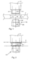
Figure 1 illustrates a first phase of a fastening arrangement in which the parts are still detached from one another; -
Figure 2 illustrates a fastening arrangement with an inner conductor already positioned into an opening in the fastening arrangement; -
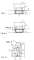
Figure 3 illustrates a fastening arrangement with an expander already inserted into an inner space of the inner conductor; -
Figure 4A illustrates the situation ofFigure 3 , added with a circle denoting a deformation area; -
Figure 4B illustrates a partial enlargement ofFigure 4A ; -
Figure 5 illustrates a version where the opening in the fastening surface structure is conical; -
Figure 6 illustrates a version where the opening in the fastening surface structure is cylindrical; -
Figure 7 illustrates an expander detachably fastened to the lower end of the inner conductor; -
Figure 8 is a schematic side view of a resonator structure; -
Figure 9 is a schematic top view of a resonator structure, seen from underneath a cover end into the direction of a bottom end. - With reference to the Figures, and to
Figures 7 and8 in particular, it is stated that the disclosure relates to afilter 1 comprising ahousing structure 2, which in turn comprises awall structure 3 and ends 4 and 5,end 4 providing thebottom 4 andend 5 the cover. Thewall structure 3 and the ends 4-5 form at least one compartment into thehousing structure 2; the present example comprising four compartments 11-14. In addition, thefilter 1 comprises at least one resonator, i.e. an inner conductor; the present example comprising four inner conductors 21-24 arranged into the compartments 11-14 of thehousing structure 2. Thebottom 4 of thehousing structure 2 refers to that side of thehousing structure 2 to which the resonators are fastened, and thus also short-circuited.End 4 provides a fastening surface structure for the inner conductors.End 4 provides a fastening surface structure.References - The invention relates to the fastening of the inner conductors 21-24 to the
fastening surface structure 4. In the following, the invention will be described with reference to arrows 1-7, using theinner conductor 21 in particular as an example. - In the Figures, the
inner conductor 21, for example, and the outer conductor surrounding it, i.e. the walls of thecompartment 21, together form a resonator structure, a plural number of similar resonator structures together forming aresonator structure entity 1 as shown inFigures 8-9 . The resonator structure entity is preferably a filter. - The fastening arrangement of the inner conductor, such as
inner conductor 21, comprises afastening surface structure 4, which in turn comprises anedge 51 of an opening and anopening 52 defined by theedge 51 of the opening, the opening being formed through thefastening surface structure 4. In addition, the fastening arrangement comprises a piece to be fastened, i.e. theinner conductor 21, positioned at theopening 52 formed through thefastening surface structure 4 and extending into theopening 52. Theinner conductor 21 comprises, in turn, aninner space 210 at least at its portion facing the fastening surface structure, the inner space being defined by awall 211 comprised by theinner conductor 21, the wall extending into theopening 52 formed through thefastening surface structure 4. Theinner space 210 does not necessarily need to be provided in other parts of theinner conductor 21 than in the part where the inner conductor is in theopening 52 of the fastening surface structure. The fastening arrangement comprises anexpander 100 brought and thereby fastened in place into theinner space 210 of theinner conductor 21 placed in theopening 52 formed through thefastening surface structure 4, the expander being used for pressing thewall 211 of theinner conductor 21 surrounding theinner space 210 in the inner conductor in a radial direction against theedge 51 of theopening 52 formed through thefastening surface structure 4 at least on the portion of the longitudinal area of theopening 52 where thewall 211 surrounding theinner space 210 of theinner conductor 21 coincides with theedge 51 of theopening 52 formed through thefastening surface structure 4. - In an arrangement according to a preferred embodiment, the pressing is provided by arranging at least one area where the pressure is high, whereas in other areas it is lower, or there is no contact at all to the wall of the inner conductor. An area in this context refers to a annular area. This allows a local pressing force to be exerted on a small area, instead of providing a uniform pressure in the entire area of the
opening 52 formed through thefastening surface structure 4, which would not be sufficiently strong. In other words, the arrangement according to the preferred embodiment in question is such that thewall 211 ofinner conductor 21 surrounding theinner space 210 of theinner conductor 21 is pressed against theedge 51 of the opening formed through thefastening surface structure 4 only in the portion of the opening area where thewall 211 surrounding theinner space 210 of theinner conductor 21 coincides with the edge of the opening formed through the fastening surface structure. Since the compartment chamber of theresonance circuit inner conductor 21, the arrangement according to the preferred embodiment is such that thewall 211 of theinner conductor 21 surrounding theinner space 210 is pressed with theexpander 100 against theedge 51 of theopening 52 formed through thefastening surface structure 4 on the side of thefastening surface 4 facing theinner conductor 21. In addition to thearea 301 referred to, the other side can also be sealed in the preferred embodiment, asecond area 302 where the wall of theinner conductor 21 surrounding theinner space 210 of the inner conductor is pressed with theexpander 100 against the edge of the opening formed through the wall of the fastening surface structure then being on the opposite edge of the fastening surface structure with regard to the inner conductor. The above two-sided pressure sealing provides further improved tightness. As stated above, thepressure areas expander 100 on thewall 211 of theinner conductor 21 and further from thewall 211 of theinner conductor 21 to theedge 51 of theopening 52 in thefastening surface structure 4 and still further to the area of the fastening surface structure surrounding the edge of the opening. In the arrangement ofFigure 2 , which shows the situation prevailing before the expander is brought in place, there are one ormore points annular pressure areas points wall 211 to be fitted to the opening of the fastening surface, i.e. the distance may be equal to a minimal clearance, such as 10 micrometers, whereas in the mid-area of the opening, in its longitudinal direction, the distance may be as much as one millimeter because that area does not necessarily need to be pressed tightly at all. Consequently, there are one or more points 450 where the distance between theedge 51 of the opening in the fastening structure and thewall 210 of theinner conductor 21 is greater than elsewhere and thus theedge 51 of the opening and thewall 211 of theinner conductor 21 remain at a distance from each other even after the expander has been forced in place, as shown inFigures 3, 4A, 4B , or at least the pressing force at these points is lower than at thepoints - With reference to
Figures 4A and 4B in particular, it is stated that the diameter of theexpander 100, the diameter of theinner space 210 of theinner conductor 21, the outer diameter of thewall 211 surrounding theinner space 210 of theinner conductor 21, and the diameter of theopening 52 formed through thefastening surface structure 4 are selected so that by pressing thewall 211 surrounding theinner space 210 of theinner conductor 21 against theedge 51 of theopening 52 of thefastening surface structure 4 theexpander 100 brought in place causes adeformation 400 on the area surrounding the edge of the opening of thefastening surface structure 4. - Since the pressure provided by the expander first acts on the
wall 211 of theinner conductor 21, in the preferred embodiment the diameter of theexpander 100, the diameter of theinner space 210 of theinner conductor 21, the outer diameter of thewall 211 surrounding the inner space of theinner conductor 21, and the diameter of theopening 52 formed through thefastening surface structure 4 are selected so that by pressing thewall 211 surrounding theinner space 210 of theinner conductor 21 against the edge of the opening of the fastening surface structure theexpander 100 brought in place causes adeformation 500 on the wall of the inner conductor surrounding the inner space of the inner conductor. - A general statement relating to one or both of the
above deformations - With regard to the deformations, particularly the
deformation 400 caused on the fastening surface structure, it is stated that thedeformation 400 does not necessarily have to be adetectable protrusion 400, although a protrusion provides better tightness and allows the fastening achieved to be better verified. - A prerequisite for the pressure and the deformation is tension. For this reason, in the preferred arrangement the diameter of the
expander 100 and that of theinner space 210 of theinner conductor 21 are selected so that when brought in place, the expander causes a tension between theexpander 100 and the wall of the inner space of the inner conductor. Correspondingly, the outer diameter of thewall 211 surrounding theinner space 210 of theinner conductor 21 and the diameter of theopening 52 formed through thefastening surface structure 4 are selected in the preferred embodiment so that when brought in place, theexpander 100 causes a tension between the outer surface of thewall 211 surrounding theinner space 210 of theinner conductor 21 and the opening formed through thefastening surface structure 4. - A preferred expander comprises a narrowing
bevel 600. The bevel facilitates mounting and enhances pressure. The surface of the expander is thus preferably conical. The conical shape preferably comprises two portions, i.e. on the outer surface of theexpander 100 there is aguide bevel 700 at least the tip of which is narrower than the diameter of the inner space of the inner conductor, the slope of the guide bevel being selected to be between 5 and 45 degrees. The slope of the narrowing bevel is selected to be between 0.5 and 5 degrees. - The
expander 100 is springy in the radial direction so that when brought in place it causes a tension but does not damage the area surrounding it. The expander comprises a longitudinal throughhole 800, i.e. the expander is sleeve-like and thus springy. The thickness of the expander wall with regard to the outer diameter of the expander must be small, for example 5-10% of the outer diameter of the expander. Theexpander 100 comprises an outer surface through which theexpander 100 presses the inner conductor wall defining the inner space of the inner conductor against theedge 51 of theopening 52 in the fastening surface structure. With regard to the sleeve-like expander, it is stated that to make the expander springy in the radial direction, the expander thus comprises an annular wall and a longitudinal throughhole 800 defined by the annular wall, the expander thereby having a sleeve-like form. It is also stated that the invention incorporates the principle that to make the expander springy in the radial direction, it comprises an annular wall and an inner space defined by the annular expander wall. In other words, the structure of the expander may as described above, i.e. it may be a sleeve-like structure, due to the through hole, or the structure may be closed at one end of the inner space. In the latter case, where one end of the expander would be closed, the inner space formed would be nest-like. If a solution is chosen where one end of the expander is closed, then the expander is preferably closed at the end that is lower in the Figures, the closed end thus closing the opening in the fastening surface and the resonator opening therein. - To ensure efficient space utilization, the lower end of the resonator does not extend out of the opening in the fastening surface, which is one of the drawbacks of a prior art structure.
- Let us then discuss the invention when applied as a method for fastening an inner conductor, such as
inner conductor 21, of a resonator structure. The method involves fastening theinner conductor 21 of the resonator structure to thefastening surface structure 4. - The
inner conductor 21 is fastened at theopening 52 in thefastening surface structure 4 by inserting anexpander 4, which is springy in the radial direction, into theinner space 210 of theinner conductor 21 positioned at the opening in thefastening surface structure 4, the expander being used for pressing thewall 211 of theinner conductor 21 surrounding theinner space 210 of theinner conductor 21 against theedge 51 of theopening 52 formed through thefastening surface structure 4 at least on the portion of the opening area where thewall 211 surrounding theinner space 210 of theinner conductor 21 coincides with theedge 51 of theopening 52 formed through thefastening surface structure 4. - The expander is preferably used in the method for producing a deformation on the
wall 211 of the inner conductor. Correspondingly, theexpander 100 is preferably used for producing a deformation through the inner conductor wall on the area surrounding the opening in the fastening surface structure. The expander is used for causing a tension between the expander and the inner conductor wall, and between the inner conductor wall and the edge of the opening in the fastening surface structure. The mounting and dimensioning of the elements involved in the method are preferably such that the expander is specifically forced in place into theinner space 211 of the inner conductor in the area of theopening 52 in thefastening surface structure 4. The applicant considers this to be a good method because no subsequent measures are required. An alternative is to simply insert theexpander 100 somehow into the inner space of theinner conductor 21 and then provide a pressure between the expander and the wall surrounding the inner space of the inner conductor by applying for example thermal treatment, or some other method. - The examples shown in the Figures illustrate a preferred version where the
expander 100 is inserted into the inner space of the inner conductor from the opposite direction with regard to the direction from which theinner conductor 21 is positioned at theopening 52 of thefastening surface structure 4. The applicant considers the method in question to be a good one, although in some embodiments and applications the expander can also be inserted from the same direction as the inner conductor, i.e. one alternative would be to insert the expander from the open free end of the inner conductor into the inner space of the inner conductor and further towards thefastening surface 4. - If the expander is forced into the inner space of the inner conductor, then the diameter of the
expander 100 is preferably 3-15% greater than the diameter of the inner space of the inner conductor. According to an example, the diameter of the expander is 0.3 mm greater than the diameter of the inner space of the inner conductor. In another example an inner conductor which is 10 mm thick has an inner space the diameter of which is 8 mm. In this case, the diameter of theexpander 100 might be for example 1 mm greater than that of the inner space. - The inner conductor is placed into the opening in the base plate, and the sleeve is gradually pressed into the hollow inner conductor from underneath the plate. The sleeve compresses slightly in the radial direction, and the inner conductor tube gives way in the radial direction. In the end, when the sleeve is pressed for example to the level of the inner conductor end/the plate surface, a radial pressing force is provided at the upper junction interface against the edge of the opening in the plate, thereby causing the root to be sealed.
- The term 'inner conductor' refers not only to the actual inner conductor, such as 21-24, but also to an inner conductor 25 of
Figures 8-9 which is in the vicinity of the actual inner conductor and galvanically connected to a signal input, such as an RX or TX coupling unit, or galvanically connected to a signal output, such as an antenna coupling unit. This type of inner conductor, which is called a tenoned resonator, is used either for supplying a signal for example to the first resonance circuit of a resonance structure or for forwarding a filtered signal onward for example from the last resonance circuit in a resonance structure. - The process is question is preferably specifically forcing, i.e. the outer diameter of the expander is greater than the diameter of the inner space of the inner conductor. Alternatively, the embodiment in question may be one where prior to the final work phase, the outer diameter of the expander is greater than the diameter of the inner space of the inner conductor. The expander is first loose and can therefore be inserted into the inner space of the conductor without resistance, the expander being then expanded by applying thermal treatment, for example, or some other means.
- The expander may be made of one or more parts. If the expander is made of two parts, then the parts of the expander may be either partially or entirely one inside the other. The second part of the expander may be used for expanding the first, outer part in the radial direction to allow the outer expander part to expand the inner conductor wall surrounding it towards the opening in the fastening surface. The resonator structure of the invention, i.e. preferably a filter, can be used for example in radio transmitters, receivers or in transceivers, such as base stations of cellular radio networks. In such cases it is apparent that the filter also comprises an antenna coupling point and an RX coupling point, to allow the signal to be supplied to the base station receiver, and a TX coupling point, where signals coming from a base station transmitter, for example, are supplied to. The present invention can also be applied in other radio transceivers or radio frequency devices than cellular radio network base stations.
-
Figure 6 illustrates a version where the opening provided for the inner conductor in the fastening surface structure is cylindrical, i.e. the diameter of the opening is equal in the entire area of the opening. The version in question is particularly well applicable if the fastening surface structure is thin, for example less than 2 mm. - With reference to
Figures 1 to 3 and toFigure 7, Figure 7 shows anexpander 100 which is detachably fastened to the end of theinner conductor 21. The inner conductor and theexpander 100 would thus first compose an integral piece, such as a machining piece. The structure shown inFigure 7 is used by placing theinner conductor 21, together with theexpander 100 fastened thereto, to theopening 52 in thefastening surface 4 so that at least theinner space 210 of the inner conductor which is in the immediate vicinity of theexpander 100 is inside theopening 52. Then a work phase takes place, such as a strike directed to the common longitudinal direction of the expander and the inner conductor, theexpander 100 being thereby first detached from theinner conductor 21 as a separate piece, but, since the striking motion still continues, theexpander 100 enters further into theinner space 210 of theinner conductor 21, thus causing a pressure to thewall 211 of theinner conductor 21 and from there on to theedge 51 of theopening 52 in the fastening surface structure. - The
inner conductor 21 of the preferred embodiment of the invention is annealed metal, preferably steel. Thefastening surface structure 4 is preferably made of aluminium, and theexpander 100 preferably of brass. - Although the invention is described above with reference to examples shown in the fastened drawings, it is apparent that the invention is not restricted to them, but can vary in many ways within the inventive idea disclosed in the fastened claims.
Claims (30)
- A fastening arrangement for an inner conductor of a resonator structure, the arrangement comprising
a fastening surface structure (4) comprising an edge (51) of an opening and an opening (52) defined by the edge of the opening, the opening being formed through the fastening surface structure;
an inner conductor (21) of a resonator structure at the opening formed through the fastening surface structure, the inner conductor comprising an inner space (210) at least in the portion facing the fastening surface structure, which inner space is defined by the wall (211) of the inner conductor, the wall extending into the opening formed through the fastening surface structure;
an expander (100), springy in the radial direction, which is brought and thereby fastened in place into the inner space of the inner conductor placed into the opening formed through the fastening structure, the expander being used for pressing the inner conductor wall surrounding the inner space of the inner conductor in a radial direction against the edge of the opening formed through the fastening structure at least on the portion of the opening area where the wall surrounding the inner space of the inner conductor coincides with the edge of the opening formed through the fastening surface structure,
characterized in that to make the expander springy in the radial direction, the expander comprises an annular wall and a longitudinal through hole (800) defined by the annular wall, the expander thus having a sleeve-like form. - A fastening arrangement according to claim 1, characterized in that the diameter of the expander is greater than the diameter of the inner space of the inner conductor, so that the expander brought in place and pressing the wall surrounding the inner space of the inner conductor against the edge of the opening in the fastening surface structure causes a deformation on the area surrounding the edge of the opening in the fastening surface structure.
- A fastening arrangement according to claim 1, characterized in that the diameter of the expander is greater than the diameter of the inner space of the inner conductor so that the expander brought in place and pressing the wall surrounding the inner space of the inner conductor against the edge of the opening in the fastening surface structure causes a deformation on the wall of the inner conductor surrounding the inner space of the inner conductor.
- A fastening arrangement according to claim 1, characterized in that the diameter of the expander is greater than the diameter of the inner space of the inner conductor so that the expander brought in place causes a tension between the expander and the wall of the inner space of the inner conductor.
- A fastening arrangement according to claim 1, characterized in that the expander brought in place causes a tension between the outer surface of the wall surrounding the inner space of the inner conductor and the opening formed through the fastening surface structure.
- A fastening arrangement according to claim 1, characterized in that the inner conductor wall surrounding the inner space is pressed against the edge of the opening formed through the wall of the fastening surface structure only on the portion of the opening area where the wall surrounding the inner space of the inner conductor coincides with the edge of the opening formed through the fastening surface structure.
- A fastening arrangement according to claim 6, characterized in that the portion where the inner conductor wall surrounding the inner space is pressed against the edge of the opening formed through the wall of the fastening surface structure is on the fastening surface side facing the inner conductor.
- A fastening arrangement according to claim 7, characterized in that a second portion where the inner conductor wall surrounding the inner space is pressed against the edge of the opening formed through the wall of the fastening surface structure is on the fastening surface structure side facing away from the inner conductor.
- A fastening arrangement according to claim 1 or 6, characterized in that the arrangement comprises one or more points between the edge of the opening and the inner conductor wall where the distance between the edge of the opening and the inner conductor wall is shorter than in other parts, where it is thus greater.
- A fastening arrangement according to claim 9, characterized in that the edge of the opening and the inner conductor wall remain at a distance from one another in the one or more points where the distance between the edge of the opening and the inner conductor wall is greater than elsewhere, or the pressing force in these points is at least lower than in the points where the distance between the edge of the opening and the inner conductor wall is shorter.
- A fastening arrangement according to claim 1, characterized in that the expander comprises an outer surface that allows the expander to press the inner conductor wall defining the inner space of the inner conductor against the edge of the opening in the fastening surface structure.
- A fastening arrangement according to claim 10, characterized in that the diameter of the expander is 3 to 15% greater than the diameter of the inner space of the inner conductor.
- A fastening arrangement according to claim 1 or 12, characterized in that the diameter of the expander is at least 0.3 mm greater than the diameter of the inner space of the inner conductor.
- A fastening arrangement according to claim 11, characterized in that to allow the tip of the expander to be more easily inserted into the inner space of the inner conductor, the outer surface of the expander is provided with a guide bevel (700) at least the tip of which is narrower than the diameter of the inner space of the inner conductor.
- A fastening arrangement according to claim 11, characterized in that the outer surface of the expander is provided with a narrowing bevel (600).
- A fastening arrangement according to claim 1, characterized in that the slope of the narrowing bevel with regard to the longitudinal direction of the expander is smaller than the slope of the guide bevel.
- A fastening arrangement according to claim 1, characterized in that the slope of the narrowing bevel is selected to be between 0.5 and 5 degrees.
- A fastening arrangement according to claim 1, characterized in that the slope of the guide bevel is selected to be between 5 and 45 degrees.
- A fastening arrangement according to claim 1, characterized in that the expander is fastened from the opposite side of the fastening surface structure with regard to the inner conductor to be fastened with the expander.
- A fastening arrangement according to claim 1, characterized in that to make the expander springy in the radial direction, the expander comprises a annular wall and an inner space defined by the annular expander wall.
- A fastening arrangement according to claim 1, 2, or 3, characterized in that the expander forms a deformation area on a section of the joint between the wall surrounding the inner space of the inner conductor and the edge of the opening in the fastening surface structure, the section being on the same side of the fastening surface in the fastening arrangement as the inner conductor.
- A method for fastening an inner conductor (21) of a resonator structure to a fastening surface structure (4), wherein the inner conductor is fastened at an opening (52) in the fastening surface structure by inserting an expander (100), which is springy in the radial direction, into an inner space (210) of the inner conductor positioned at the opening in the fastening surface structure, the expander being used for pressing the inner conductor wall surrounding the inner space of the inner conductor in a radial direction against an edge (51) of the opening formed through the fastening surface structure at least on the portion of the opening area where the wall surrounding the inner space of the inner conductor coincides with the edge of the opening formed through the fastening surface structure, characterized in that to make the expander springy in the radial direction, the expander comprises an annular wall and a longitudinal through hole (800) defined by the annular wall, the expander thus having a sleeve-like form.
- A method according to claim 22, characterized in that the expander is used for causing a deformation on the inner conductor wall.
- A method according to claim 22, characterized in that the expander is used for causing a deformation through the inner conductor wall on the area surrounding the opening in the fastening surface structure.
- A method according to claim 22, characterized in that the expander is used for producing a tension between the expander and the inner conductor wall.
- A method according to claim 22, characterized in that the expander is used for producing a tension between the inner conductor wall and the edge of the opening in the fastening surface structure.
- A method according to claim 22, characterized in that the expander is forced in place into the inner space of the inner conductor which is within the area of the opening in the fastening surface structure.
- A method according to claim 22, characterized in that the expander is inserted into the inner space of the inner conductor and the expander is made to press against the wall surrounding the inner space of the inner conductor.
- A method according to claim 22, characterized in that the expander is inserted into the inner space of the inner conductor from the opposite direction with regard to the direction from which the inner conductor is inserted into the opening in the fastening surface structure.
- A method according to claim 22, 23 or 24, characterized in that the expander brought in place forms a deformation area on a section of the joint between the wall surrounding the inner space of the inner conductor and the edge of the opening in the fastening surface structure, the section being on the same side of the fastening surface of the fastening arrangement as the inner conductor.
Applications Claiming Priority (2)
| Application Number | Priority Date | Filing Date | Title |
|---|---|---|---|
| FI992580A FI115333B (en) | 1999-12-01 | 1999-12-01 | Fixing arrangement for inner conduit in a resonator structure and method for attaching such an inner conduit |
| FI992580 | 1999-12-01 |
Publications (3)
| Publication Number | Publication Date |
|---|---|
| EP1107350A2 EP1107350A2 (en) | 2001-06-13 |
| EP1107350A3 EP1107350A3 (en) | 2002-09-11 |
| EP1107350B1 true EP1107350B1 (en) | 2011-09-07 |
Family
ID=8555675
Family Applications (1)
| Application Number | Title | Priority Date | Filing Date |
|---|---|---|---|
| EP00660219A Expired - Lifetime EP1107350B1 (en) | 1999-12-01 | 2000-11-30 | Method and arrangement for fastening inner conductor of resonator structure |
Country Status (4)
| Country | Link |
|---|---|
| US (1) | US6501349B2 (en) |
| EP (1) | EP1107350B1 (en) |
| AT (1) | ATE523921T1 (en) |
| FI (1) | FI115333B (en) |
Families Citing this family (5)
| Publication number | Priority date | Publication date | Assignee | Title |
|---|---|---|---|---|
| FI114252B (en) * | 1999-12-01 | 2004-09-15 | Remec Oy | Process for producing resonator inner conductor and such conductor |
| US7096565B2 (en) * | 2003-06-19 | 2006-08-29 | Powerwave Technologies, Inc. | Flanged inner conductor coaxial resonators |
| DE102006005183B4 (en) * | 2006-02-06 | 2014-12-24 | Robert Bosch Gmbh | Assembly with a control unit housing and a pump housing |
| KR101205958B1 (en) * | 2011-05-23 | 2012-11-28 | 한국전자통신연구원 | High-voltage wideband pulse load |
| KR20200004551A (en) * | 2018-07-04 | 2020-01-14 | (주)웨이브텍 | Combination Structures Between Components In Radio Frequency Filters And Radio Frequency Filters Including The Same Combination Structures |
Family Cites Families (6)
| Publication number | Priority date | Publication date | Assignee | Title |
|---|---|---|---|---|
| BE563966A (en) * | 1957-03-12 | |||
| FI89115C (en) * | 1991-09-18 | 1993-08-10 | Lk Products Oy | FOERFARANDE FOER FAESTANDET AV EN RESONATORSTAV MOT ETT HOEGFREKVENSFILTERS VAEGG OCH HOEGFREKVENSFILTER |
| JPH08195607A (en) * | 1995-01-13 | 1996-07-30 | Kokusai Electric Co Ltd | Semi-coaxial cavity resonator |
| US5834993A (en) | 1996-08-20 | 1998-11-10 | Hughes Electronics Corporation | Passive microwave structure and methods having reduced passive intermodulation |
| US6114928A (en) * | 1997-11-10 | 2000-09-05 | Smith; Patrick | Mounting assemblies for tubular members used in RF filters |
| FI106658B (en) | 1997-12-15 | 2001-03-15 | Adc Solitra Oy | Filters and controls |
-
1999
- 1999-12-01 FI FI992580A patent/FI115333B/en not_active IP Right Cessation
-
2000
- 2000-11-30 AT AT00660219T patent/ATE523921T1/en not_active IP Right Cessation
- 2000-11-30 EP EP00660219A patent/EP1107350B1/en not_active Expired - Lifetime
- 2000-12-01 US US09/727,936 patent/US6501349B2/en not_active Expired - Lifetime
Also Published As
| Publication number | Publication date |
|---|---|
| EP1107350A3 (en) | 2002-09-11 |
| ATE523921T1 (en) | 2011-09-15 |
| US6501349B2 (en) | 2002-12-31 |
| EP1107350A2 (en) | 2001-06-13 |
| FI19992580L (en) | 2001-06-02 |
| FI115333B (en) | 2005-04-15 |
| US20010002810A1 (en) | 2001-06-07 |
Similar Documents
| Publication | Publication Date | Title |
|---|---|---|
| CN116053737B (en) | Wireless frequency filter with cavity structure | |
| US5990763A (en) | Filter having part of a resonator and integral shell extruded from one basic block | |
| US6501349B2 (en) | Method and arrangement for fastening inner conductor of resonator structure | |
| CN101938027B (en) | Communication equipment, cavity filter and resonance tube thereof | |
| EP0865094A3 (en) | Wave filter having two or more coaxial dielectric resonators in juxtaposition | |
| JP3351408B2 (en) | Waveguide connection method and connection structure | |
| KR20110013956A (en) | Cover combination method of radio frequency filter and radio frequency filter by the method | |
| US6294968B1 (en) | Dielectric filter and process for producing same | |
| US6742240B2 (en) | Method for attaching resonator part | |
| US7557679B2 (en) | Sealed microwave feedthrough | |
| EP1111709B1 (en) | Method of manufacturing the inner conductor of a resonator, and inner conductor of a resonator | |
| CN210926247U (en) | Microwave device cavity and microwave device | |
| EP0533394A2 (en) | Filter comprising a resonator rod mounted on a base plate | |
| KR100561614B1 (en) | Connection structure and burring method of aluminum pipe | |
| US20250219276A1 (en) | Filter for communication device and manufacturing method therefor | |
| KR0121528Y1 (en) | Condenser | |
| US5890913A (en) | Connection arrangement | |
| KR101165872B1 (en) | High frequency filter | |
| US20250192410A1 (en) | Filter for communication device | |
| CN220122082U (en) | Filter and communication equipment | |
| KR19980041642U (en) | Antenna terminals | |
| CN207925696U (en) | Include the radio-frequency unit of coaxial cable connection | |
| US6949987B2 (en) | Dielectric electronic component with attenuation adjustment electrode and method of adjusting attenuation characteristics of the same | |
| WO2004043124A1 (en) | High-frequency device | |
| CA1081807A (en) | Device provided with a band-pass filter constructed from coaxial resonator cavities |
Legal Events
| Date | Code | Title | Description |
|---|---|---|---|
| PUAI | Public reference made under article 153(3) epc to a published international application that has entered the european phase |
Free format text: ORIGINAL CODE: 0009012 |
|
| AK | Designated contracting states |
Kind code of ref document: A2 Designated state(s): AT BE CH CY DE DK ES FI FR GB GR IE IT LI LU MC NL PT SE TR |
|
| AX | Request for extension of the european patent |
Free format text: AL;LT;LV;MK;RO;SI |
|
| PUAL | Search report despatched |
Free format text: ORIGINAL CODE: 0009013 |
|
| AK | Designated contracting states |
Kind code of ref document: A3 Designated state(s): AT BE CH CY DE DK ES FI FR GB GR IE IT LI LU MC NL PT SE TR |
|
| AX | Request for extension of the european patent |
Free format text: AL;LT;LV;MK;RO;SI |
|
| 17P | Request for examination filed |
Effective date: 20030204 |
|
| RAP1 | Party data changed (applicant data changed or rights of an application transferred) |
Owner name: REMEC OY |
|
| AKX | Designation fees paid |
Designated state(s): AT BE CH CY DE DK ES FI FR GB GR IE IT LI LU MC NL PT SE TR |
|
| 17Q | First examination report despatched |
Effective date: 20061011 |
|
| GRAP | Despatch of communication of intention to grant a patent |
Free format text: ORIGINAL CODE: EPIDOSNIGR1 |
|
| GRAS | Grant fee paid |
Free format text: ORIGINAL CODE: EPIDOSNIGR3 |
|
| GRAA | (expected) grant |
Free format text: ORIGINAL CODE: 0009210 |
|
| AK | Designated contracting states |
Kind code of ref document: B1 Designated state(s): AT BE CH CY DE DK ES FI FR GB GR IE IT LI LU MC NL PT SE TR |
|
| REG | Reference to a national code |
Ref country code: GB Ref legal event code: FG4D |
|
| REG | Reference to a national code |
Ref country code: CH Ref legal event code: EP |
|
| REG | Reference to a national code |
Ref country code: IE Ref legal event code: FG4D |
|
| REG | Reference to a national code |
Ref country code: DE Ref legal event code: R081 Ref document number: 60046421 Country of ref document: DE Owner name: INTEL CORPORATION, SANTA CLARA, US Free format text: FORMER OWNER: ADC TELECOMMUNICATION OY, OULU, FI |
|
| REG | Reference to a national code |
Ref country code: DE Ref legal event code: R096 Ref document number: 60046421 Country of ref document: DE Effective date: 20111201 |
|
| REG | Reference to a national code |
Ref country code: SE Ref legal event code: TRGR |
|
| REG | Reference to a national code |
Ref country code: NL Ref legal event code: VDEP Effective date: 20110907 |
|
| PG25 | Lapsed in a contracting state [announced via postgrant information from national office to epo] |
Ref country code: FI Free format text: LAPSE BECAUSE OF FAILURE TO SUBMIT A TRANSLATION OF THE DESCRIPTION OR TO PAY THE FEE WITHIN THE PRESCRIBED TIME-LIMIT Effective date: 20110907 |
|
| PG25 | Lapsed in a contracting state [announced via postgrant information from national office to epo] |
Ref country code: AT Free format text: LAPSE BECAUSE OF FAILURE TO SUBMIT A TRANSLATION OF THE DESCRIPTION OR TO PAY THE FEE WITHIN THE PRESCRIBED TIME-LIMIT Effective date: 20110907 Ref country code: GR Free format text: LAPSE BECAUSE OF FAILURE TO SUBMIT A TRANSLATION OF THE DESCRIPTION OR TO PAY THE FEE WITHIN THE PRESCRIBED TIME-LIMIT Effective date: 20111208 Ref country code: CY Free format text: LAPSE BECAUSE OF FAILURE TO SUBMIT A TRANSLATION OF THE DESCRIPTION OR TO PAY THE FEE WITHIN THE PRESCRIBED TIME-LIMIT Effective date: 20110907 |
|
| REG | Reference to a national code |
Ref country code: AT Ref legal event code: MK05 Ref document number: 523921 Country of ref document: AT Kind code of ref document: T Effective date: 20110907 |
|
| PG25 | Lapsed in a contracting state [announced via postgrant information from national office to epo] |
Ref country code: BE Free format text: LAPSE BECAUSE OF FAILURE TO SUBMIT A TRANSLATION OF THE DESCRIPTION OR TO PAY THE FEE WITHIN THE PRESCRIBED TIME-LIMIT Effective date: 20110907 |
|
| PG25 | Lapsed in a contracting state [announced via postgrant information from national office to epo] |
Ref country code: PT Free format text: LAPSE BECAUSE OF FAILURE TO SUBMIT A TRANSLATION OF THE DESCRIPTION OR TO PAY THE FEE WITHIN THE PRESCRIBED TIME-LIMIT Effective date: 20120109 Ref country code: NL Free format text: LAPSE BECAUSE OF FAILURE TO SUBMIT A TRANSLATION OF THE DESCRIPTION OR TO PAY THE FEE WITHIN THE PRESCRIBED TIME-LIMIT Effective date: 20110907 |
|
| PG25 | Lapsed in a contracting state [announced via postgrant information from national office to epo] |
Ref country code: MC Free format text: LAPSE BECAUSE OF NON-PAYMENT OF DUE FEES Effective date: 20111130 |
|
| REG | Reference to a national code |
Ref country code: CH Ref legal event code: PL |
|
| PLBE | No opposition filed within time limit |
Free format text: ORIGINAL CODE: 0009261 |
|
| STAA | Information on the status of an ep patent application or granted ep patent |
Free format text: STATUS: NO OPPOSITION FILED WITHIN TIME LIMIT |
|
| PG25 | Lapsed in a contracting state [announced via postgrant information from national office to epo] |
Ref country code: CH Free format text: LAPSE BECAUSE OF NON-PAYMENT OF DUE FEES Effective date: 20111130 Ref country code: DK Free format text: LAPSE BECAUSE OF FAILURE TO SUBMIT A TRANSLATION OF THE DESCRIPTION OR TO PAY THE FEE WITHIN THE PRESCRIBED TIME-LIMIT Effective date: 20110907 Ref country code: LI Free format text: LAPSE BECAUSE OF NON-PAYMENT OF DUE FEES Effective date: 20111130 |
|
| 26N | No opposition filed |
Effective date: 20120611 |
|
| REG | Reference to a national code |
Ref country code: IE Ref legal event code: MM4A |
|
| REG | Reference to a national code |
Ref country code: DE Ref legal event code: R097 Ref document number: 60046421 Country of ref document: DE Effective date: 20120611 |
|
| PG25 | Lapsed in a contracting state [announced via postgrant information from national office to epo] |
Ref country code: IE Free format text: LAPSE BECAUSE OF NON-PAYMENT OF DUE FEES Effective date: 20111130 |
|
| PG25 | Lapsed in a contracting state [announced via postgrant information from national office to epo] |
Ref country code: LU Free format text: LAPSE BECAUSE OF NON-PAYMENT OF DUE FEES Effective date: 20111130 |
|
| PG25 | Lapsed in a contracting state [announced via postgrant information from national office to epo] |
Ref country code: TR Free format text: LAPSE BECAUSE OF FAILURE TO SUBMIT A TRANSLATION OF THE DESCRIPTION OR TO PAY THE FEE WITHIN THE PRESCRIBED TIME-LIMIT Effective date: 20110907 |
|
| PG25 | Lapsed in a contracting state [announced via postgrant information from national office to epo] |
Ref country code: ES Free format text: LAPSE BECAUSE OF FAILURE TO SUBMIT A TRANSLATION OF THE DESCRIPTION OR TO PAY THE FEE WITHIN THE PRESCRIBED TIME-LIMIT Effective date: 20111218 |
|
| REG | Reference to a national code |
Ref country code: FR Ref legal event code: PLFP Year of fee payment: 16 |
|
| REG | Reference to a national code |
Ref country code: DE Ref legal event code: R081 Ref document number: 60046421 Country of ref document: DE Owner name: INTEL CORPORATION, SANTA CLARA, US Free format text: FORMER OWNER: POWERWAVE FINLAND OY, 90440 KEMPELE, FI |
|
| REG | Reference to a national code |
Ref country code: FR Ref legal event code: TP Owner name: INTEL CORPORATION, US Effective date: 20160606 Ref country code: FR Ref legal event code: TP Owner name: INTEL CORPORATION, US Effective date: 20160603 |
|
| REG | Reference to a national code |
Ref country code: GB Ref legal event code: 732E Free format text: REGISTERED BETWEEN 20160728 AND 20160803 |
|
| REG | Reference to a national code |
Ref country code: GB Ref legal event code: 732E Free format text: REGISTERED BETWEEN 20160811 AND 20160817 |
|
| REG | Reference to a national code |
Ref country code: FR Ref legal event code: PLFP Year of fee payment: 17 |
|
| REG | Reference to a national code |
Ref country code: GB Ref legal event code: 732E Free format text: REGISTERED BETWEEN 20161006 AND 20161012 |
|
| REG | Reference to a national code |
Ref country code: GB Ref legal event code: 732E Free format text: REGISTERED BETWEEN 20161013 AND 20161019 |
|
| PGFP | Annual fee paid to national office [announced via postgrant information from national office to epo] |
Ref country code: DE Payment date: 20161123 Year of fee payment: 17 Ref country code: FR Payment date: 20161028 Year of fee payment: 17 |
|
| PGFP | Annual fee paid to national office [announced via postgrant information from national office to epo] |
Ref country code: IT Payment date: 20161122 Year of fee payment: 17 Ref country code: SE Payment date: 20161111 Year of fee payment: 17 |
|
| PGFP | Annual fee paid to national office [announced via postgrant information from national office to epo] |
Ref country code: GB Payment date: 20171129 Year of fee payment: 18 |
|
| REG | Reference to a national code |
Ref country code: DE Ref legal event code: R119 Ref document number: 60046421 Country of ref document: DE |
|
| PG25 | Lapsed in a contracting state [announced via postgrant information from national office to epo] |
Ref country code: SE Free format text: LAPSE BECAUSE OF NON-PAYMENT OF DUE FEES Effective date: 20171201 |
|
| REG | Reference to a national code |
Ref country code: FR Ref legal event code: ST Effective date: 20180731 |
|
| PG25 | Lapsed in a contracting state [announced via postgrant information from national office to epo] |
Ref country code: IT Free format text: LAPSE BECAUSE OF NON-PAYMENT OF DUE FEES Effective date: 20171130 Ref country code: FR Free format text: LAPSE BECAUSE OF NON-PAYMENT OF DUE FEES Effective date: 20171130 Ref country code: DE Free format text: LAPSE BECAUSE OF NON-PAYMENT OF DUE FEES Effective date: 20180602 |
|
| GBPC | Gb: european patent ceased through non-payment of renewal fee |
Effective date: 20181130 |
|
| PG25 | Lapsed in a contracting state [announced via postgrant information from national office to epo] |
Ref country code: GB Free format text: LAPSE BECAUSE OF NON-PAYMENT OF DUE FEES Effective date: 20181130 |