EP1107035A2 - Lens driving device, and apparatus for and method of manufacturing the device - Google Patents
Lens driving device, and apparatus for and method of manufacturing the device Download PDFInfo
- Publication number
- EP1107035A2 EP1107035A2 EP00309955A EP00309955A EP1107035A2 EP 1107035 A2 EP1107035 A2 EP 1107035A2 EP 00309955 A EP00309955 A EP 00309955A EP 00309955 A EP00309955 A EP 00309955A EP 1107035 A2 EP1107035 A2 EP 1107035A2
- Authority
- EP
- European Patent Office
- Prior art keywords
- projection
- depression
- elastic members
- driving apparatus
- lens
- Prior art date
- Legal status (The legal status is an assumption and is not a legal conclusion. Google has not performed a legal analysis and makes no representation as to the accuracy of the status listed.)
- Granted
Links
Images




Classifications
-
- G—PHYSICS
- G11—INFORMATION STORAGE
- G11B—INFORMATION STORAGE BASED ON RELATIVE MOVEMENT BETWEEN RECORD CARRIER AND TRANSDUCER
- G11B7/00—Recording or reproducing by optical means, e.g. recording using a thermal beam of optical radiation by modifying optical properties or the physical structure, reproducing using an optical beam at lower power by sensing optical properties; Record carriers therefor
- G11B7/08—Disposition or mounting of heads or light sources relatively to record carriers
- G11B7/09—Disposition or mounting of heads or light sources relatively to record carriers with provision for moving the light beam or focus plane for the purpose of maintaining alignment of the light beam relative to the record carrier during transducing operation, e.g. to compensate for surface irregularities of the latter or for track following
- G11B7/0925—Electromechanical actuators for lens positioning
- G11B7/0932—Details of sprung supports
-
- G—PHYSICS
- G11—INFORMATION STORAGE
- G11B—INFORMATION STORAGE BASED ON RELATIVE MOVEMENT BETWEEN RECORD CARRIER AND TRANSDUCER
- G11B7/00—Recording or reproducing by optical means, e.g. recording using a thermal beam of optical radiation by modifying optical properties or the physical structure, reproducing using an optical beam at lower power by sensing optical properties; Record carriers therefor
- G11B7/12—Heads, e.g. forming of the optical beam spot or modulation of the optical beam
- G11B7/22—Apparatus or processes for the manufacture of optical heads, e.g. assembly
Definitions
- the present invention relates to a lens driving apparatus used for information recording (information writing) into an information recording medium or information reproducing (information reading) from the information recording medium, and an apparatus and method of manufacturing the lens driving apparatus.
- a so-called pickup apparatus is provided with a lens driving apparatus for electromagnetically driving the objective lens in a focusing direction and a tracking direction to perform positioning control.
- Fig. 10 is a perspective view showing a configuration of a conventional lens driving apparatus provided in a pickup apparatus.
- This lens driving apparatus comprises a lens holder 2 in which an objective lens 1 is mounted and a substrate 7 for cantilevering the lens holder 2 by four elastic wires 3, 4, 5, 6.
- a magnet 18 and yokes 19, 20 fixed in the substrate 7 and an electric circuit board 21 fixed in the lens holder 2 are provided between the lens holder 2 and the substrate 7, and a focusing coil and a tracking coil (not shown) are formed on the electric circuit board 21.
- the electric circuit board 21 in which the focusing coil and the tracking coil are formed is provided between the yokes 19 and 20 at a certain distance.
- magnetic force is generated in a focusing direction ⁇ F by supplying a driving current to the focusing coil and focusing control is performed by finely adjusting a position of the focusing direction ⁇ F of the objective lens 1 and the lens holder 2 by means of this magnetic force.
- magnetic force is generated in a tracking direction ⁇ T by supplying a driving current to the tracking coil and tracking control is performed by finely adjusting a position of the tracking direction ⁇ T of the objective lens 1 and the lens holder 2 by means of this magnetic force.
- the lens holder 2 is cantilevered to the substrate 7 through the four elastic wires 3, 4, 5, 6, so that the lens holder 2 becomes deformed freely in response to the magnetic force generated in the case of the focusing control and the tracking control.
- the objective lens 1 and the lens holder 2 are deviated in a desired direction with them floated and thus, information recording into an information recording medium DSC or information reproducing from the information recording medium DSC can be performed with high accuracy.
- the elastic wires 3, 4, 5, 6 are fixed in the substrate 7 while being buried in a state surrounded by the ultraviolet cure resins 14, 15, 16, 17 acting as a damping material, so that the ultraviolet cure resins 14, 15, 16, 17 absorb vibrations occurring in the elastic wires 3, 4, 5, 6 in the case of the focusing control and the tracking control, and it is constructed so as to achieve the focusing control and the tracking control with good responsiveness.
- the substrate 7 is mounted on a movable body 24 supported by a pair of guide shafts 22, 23 provided in a chassis of a body of an information recording and reproducing apparatus. Then, by forward or backward moving the movable body 24 along a longitudinal direction of the guide shafts 22, 23, this lens driving apparatus is forward or backward moved in a radial direction of the information recording medium DSC (the same direction as the tracking direction ⁇ T ) and further by making use in combination with the focusing control and the tracking control, it is intended to perform the information recording and information reproducing with high accuracy.
- DSC the same direction as the tracking direction ⁇ T
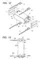
- liquid sagging occurs in case of simply filling the depression stepped portions 8, 9, 10, 11 of the substrate 7 with the ultraviolet cure resins 14, 15, 16, 17, so that the opposed pieces 12, 13 other than the substrate 7 were mounted so as to attach to the depression stepped portions 8, 9, 10, 11 and thereby the gaps capable of preventing the liquid sagging were defined and their gaps were filled with the ultraviolet cure resins 14, 15, 16, 17. Because of this, there were problems that the number of manufacturing steps increases while the number of parts increases. These problems will be described in detail with reference to Figs. 12 and 13 below.
- the substrate 7 and the opposed pieces 12, 13 are respectively molded by individual members.
- Depression stepped portions 7c, 7d, 7e, 7f for inserting the elastic wires 3, 4, 5, 6 are molded in the four corners of the substrate 7, and fitting protrusions 7g, 7h are formed on the side end of a T-shaped projection 7b of the side of the depression stepped portions 7e, 7f and fitting protrusions (not shown) similar to the fitting protrusions 7g, 7h are formed on the side end of a T-shaped projection 7a of the side of the depression stepped portions 7c, 7d.
- a through hole 13a for fitting the fitting protrusions 7g, 7h is formed in the opposed piece 13 and a through hole 12a similar to the through hole 13a is formed in the opposed piece 12.
- the opposed pieces 12, 13 were mounted in order to prevent the ultraviolet cure resins 14, 15, 16, 17 from flowing out of the depression stepped portions 7c, 7d, 7e, 7f in a state of liquid, so that there were problems that the number of manufacturing steps increases while the number of parts increases.
- the invention is implemented to overcome the problems of the conventional art, and it is an object of the invention to provide a lens driving apparatus, an apparatus and method of manufacturing the lens driving apparatus capable of reducing the number of parts and simplifying manufacturing steps.
- a lens driving apparatus of the invention is characterized in that the lens driving apparatus has a lens holder for holding an objective lens, and a substrate which supports the lens holder through elastic members and is molded with resin, and the elastic members are integrally supported in the substrate in the case of the resin molding and are provided within gaps molded in the substrate with the gaps ranging to the integrally supported portions and are buried in a damping material with which the gaps are filled.
- the lens driving apparatus is characterized in that the gaps are formed by depression portions and projection portions opposed one another molded in the proximity of the elastic members in the case of the resin molding.
- the lens driving apparatus is characterized in that the depression portions and projection portions are molded in a long shape along a longitudinal direction of the elastic members.
- the lens driving apparatus of such a construction while the substrate is integrally molded by the resin molding, the elastic members are also integrally supported in the substrate. Further, the elastic members are provided within the gaps integrally molded in the substrate by the resin molding and also are buried with the elastic members surrounded by the damping material with which the gaps are filled.
- the lens driving apparatus manufactured while reducing the number of parts and the number of manufacturing steps can be provided.
- the lens driving apparatus without liquid sagging of the damping material can be provided by filling the gaps within which the elastic members are provided with the damping material. For example, the lens driving apparatus without the liquid sagging can be provided even when using ultraviolet cure resin as the damping material.
- a lens driving apparatus of the invention is characterized in that the lens driving apparatus has a lens holder which holds an objective lens and is molded with resin, and a substrate for supporting the lens holder through elastic members, and the elastic members are integrally supported in the lens holder in the case of the resin molding and are provided within gaps molded in the lens holder with the gaps ranging to the integrally supported portions and are buried in a damping material with which the gaps are filled.
- the lens driving apparatus is characterized in that the gaps are formed by depression portions and projection portions opposed one another molded in the proximity of the elastic members in the case of the resin molding.
- the lens driving apparatus is characterized in that the depression portions and proj ection portions are molded in a long shape along a longitudinal direction of the elastic members.
- the lens driving apparatus of such a construction while the lens holder is integrally molded by the resin molding, the elastic members are also integrally supported in the lens holder. Further, the elastic members are provided within the gaps integrally molded in the lens holder by the resin molding and also are buried with the elastic members surrounded by the damping material with which the gaps are filled.
- the lens driving apparatus manufactured while reducing the number of parts and the number of manufacturing steps can be provided.
- the lens driving apparatus without liquid sagging of the damping material can be provided by filling the gaps within which the elastic members are provided with the damping material. For example, the lens driving apparatus without the liquid sagging can be provided even when using ultraviolet cure resin as the damping material.
- a manufacturing apparatus of a lens driving apparatus of the invention is characterized in that there is the manufacturing apparatus of the lens driving apparatus having a lens holder for holding an objective lens, and a substrate for supporting the lens holder through elastic members, and the manufacturing apparatus comprises a mold on which cavities having a first depression for molding a base of the substrate, a projection adjacent to the first depression, and a second depression adjacent to the projection and partially ranging to the first depression are formed, and by filling the cavities of the mold with synthetic resin with the elastic members stretched between the projection of the mold and the ranging portion of the first and second depressions, the elastic members are supported in the base molded by the synthetic resin with which the ranging portion is filled and are provided within gaps formed by the projection and thereafter are buried in a damping material by filling the gaps with the damping material.
- a manufacturing apparatus of a lens driving apparatus is characterized in that there is the manufacturing apparatus of the lens driving apparatus having a lens holder for holding an objective lens, and a substrate for supporting the lens holder through elastic members, and the manufacturing apparatus comprises a mold on which cavities having a first depression for molding a base of the lens holder, a projection adjacent to the first depression, and a second depression adjacent to the projection and partially ranging to the first depression are formed, and by filling the cavities of the mold with synthetic resin with the elastic members stretched between the projection of the mold and the ranging portion of the first and second depressions, the elastic members are supported in the base molded by the synthetic resin with which the ranging portion is filled and are provided within gaps formed by the projection and thereafter are buried in a damping material by filling the gaps with the damping material.
- the elastic members are also integrally supported in the substrate or the lens holder. Further, the elastic members are provided within the respective gaps integrally molded in the substrate or the lens holder by the resin molding and also are buried with the elastic members surrounded by the damping material with which the gaps are filled.
- the lens driving apparatus manufactured while reducing the number of parts and the number of manufacturing steps can be provided.
- the lens driving apparatus without liquid sagging of the damping material can be provided by filling the gaps within which the elastic members are provided with the damping material. For example, the lens driving apparatus without the liquid sagging can be provided even when using ultraviolet cure resin as the damping material.
- a manufacturing method of a lens driving apparatus of the invention is characterized in that there is the manufacturing method of the lens driving apparatus having a lens holder for holding an objective lens, and a substrate for supporting the lens holder through elastic members, and the manufacturing method comprises a first step of fitting the elastic members into a mold on which cavities having a first depression for molding a base of the substrate, a projection adjacent to the first depression, and a second depression adjacent to the projection and partially ranging to the first depression are formed with the elastic members stretched between the projection and the ranging portion of the first and second depressions, a second step of integrally supporting the elastic members in the base molded by the synthetic resin with which the ranging portion is filled and providing the elastic members within gaps formed by the projection between the first and second depressions by filling the cavities of the mold with synthetic resin, and a third step of burying the elastic members in a damping material by filling the gaps with the damping material after separating the mold.
- a manufacturing method of a lens driving apparatus is characterized in that there is the manufacturing method of the lens driving apparatus having a lens holder for holding an objective lens, and a substrate for supporting the lens holder through elastic members, and the manufacturing method comprises a first step of fitting the elastic members into a mold on which cavities having a first depression for molding a base of the lens holder, a projection adjacent to the first depression, and a second depression adjacent to the projection and partially ranging to the first depression are formed with the elastic members stretched between the projection and the ranging portion of the first and second depressions, a second step of integrally supporting the elastic members in the base molded by the synthetic resin with which the ranging portion is filled and providing the elastic members within gaps formed by the projection between the first and second depressions by filling the cavities of the mold with synthetic resin, and a third step of burying the elastic members in a damping material by filling the gaps with the damping material after separating the mold.
- the elastic members are also integrally supported in the substrate or the lens holder. Further, the elastic members are provided within the respective gaps integrally molded in the substrate or the lens holder by the resin molding and also are buried with the elastic members surrounded by the damping material with which the gaps are filled.
- the lens driving apparatus manufactured while reducing the number of parts and the number of manufacturing steps can be provided.
- the lens driving apparatus without liquid sagging of the damping material can be provided by filling the gaps within which the elastic members are provided with the damping material. For example, the lens driving apparatus without the liquid sagging can be provided even when using ultraviolet cure resin as the damping material.
- Fig. 1 is a perspective view showing an external configuration of a lens driving apparatus according to the embodiment
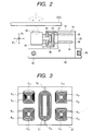
- Fig. 2 is a side view schematically showing a side shape of the lens driving apparatus.
- the lens driving apparatus is an apparatus applied to an information recording and reproducing apparatus such as CD players, DVD players or MD players, and comprises a substrate 25 and a lens holder 26 molded with synthetic resin and four elastic members (hereinafter called elastic wires) 27, 28, 29, 30 coupled between the substrate 25 and the lens holder 26.
- an information recording and reproducing apparatus such as CD players, DVD players or MD players
- the lens driving apparatus comprises a substrate 25 and a lens holder 26 molded with synthetic resin and four elastic members (hereinafter called elastic wires) 27, 28, 29, 30 coupled between the substrate 25 and the lens holder 26.
- the elastic wires 27, 28, 29, 30 are fixed in the rear ends 47, 48, 49, 50 of the substrate 25 with the elastic wires interposed into L-shaped gaps 39, 40, 41, 42 respectively defined by the projection portions 31, 32, 33, 34 and the depression stepped portions 35, 36, 37, 38 (with the elastic wires in no contact with the projection portions 31, 32, 33, 34 and the depression stepped portions 35, 36, 37, 38), and further the gaps 39, 40, 41, 42 are filled with ultraviolet cure resins 43, 44, 45, 46 acting as a damping material. That is, the elastic wires 27, 28, 29, 30 are supported in the rear ends 47, 48, 49, 50 with the elastic wires surrounded by the ultraviolet cure resins 43, 44, 45, 46.
- the rear end 48 is not drawn in Fig. 1, but the rear end 48 is located in the lower side of the rear end 47 in a manner similar to the rear end 50 located in the lower side of the rear end 49.
- integral coupling is performed by burying respective other ends of the elastic wires 27, 28, 29, 30 in four corners of the lens holder 26, and an objective lens 52 is provided in a lens mounting portion 51 formed in the center portion of the lens holder 26.
- magnetic circuit unit for performing focusing control and tracking control is provided within a gap among the lens holder 26, the substrate 25 and the elastic wires 27, 28, 29, 30.
- This magnetic circuit unit comprises yokes 54, 55 suspended and fixed in a supporting member 53 fixed on the top of the substrate 25, a magnet 56 fastened in the bottom of the yokes 54, 55, and an electric circuit board 57 provided between the yokes 54, 55 and fixed in one end of the lens holder 26.
- a focusing coil C F and four sets of tracking coils C T1 , C T2 , C T3 , C T4 as shown in Fig. 3 are patterned on the surface of the electric circuit board 57 by metal deposition or etching process, and the electric circuit board 57 is provided with the focusing coil C F and the tracking coils C T1 , C T2 , C T3 , C T4 directed to the yokes 54, 55.
- magnetic force is generated in a focusing direction ⁇ F by supplying a driving current for focusing control through electrodes P F1 , P F2 provided in both ends of the focusing coil C F and focusing control is performed by finely adjusting a position of the focusing direction ⁇ F of the objective lens 52 and the lens holder 26 by means of this magnetic force.
- magnetic force is generated in a tracking direction ⁇ T by supplying a driving current for tracking control to each electrode P 11 , P 12 , P 21 , P 22 , P 31 , P 32 , P 41 , P 42 provided in the tracking coils C T1 , C T2 , C T3 , C T4 and tracking control is performed by finely adjusting a position of the tracking direction ⁇ T of the objective lens 52 and the lens holder 26 by means of this magnetic force.
- the lens holder 26 is cantilevered to the substrate 25 through the four elastic wires 27, 28, 29, 30, so that the lens holder 26 becomes deformed freely in response to the magnetic force generated in the case of the focusing control and the tracking control.
- the objective lens 52 and the lens holder 26 are deviated in a desired direction with them floated and thus, information recording into an information recording medium DSC or information reproducing from the information recording medium DSC can be performed with high accuracy.
- the elastic wires 27, 28, 29, 30 are provided in a state surrounded by the ultraviolet cure resins 43, 44, 45, 46 acting as a damping material, so that the ultraviolet cure resins 43, 44, 45, 46 absorb vibrations occurring in the elastic wires 27, 28, 29, 30 in the case of the focusing control and the tracking control, and it is constructed so as to achieve the focusing control and the tracking control with good responsiveness.
- the substrate 25 is mounted on a movable body 60 supported by a pair of guide shafts 58, 59 provided in a chassis of a body of the information recording and reproducing apparatus such as CD players, DVD players or MD players. Then, by forward or backward moving the movable body 60 along a longitudinal direction (a vertical direction relative to the paper face) of the guide shafts 58, 59, this lens driving apparatus is forward or backward moved in a radial direction of the information recording medium DSC (the same direction as the tracking direction ⁇ T ) and further by the focusing control and the tracking control, the information recording and information reproducing with high accuracy can be performed.
- the information recording and reproducing apparatus such as CD players, DVD players or MD players.
- Fig. 4 is a perspective view showing a structure of a mold provided in the manufacturing apparatus
- Fig. 5 is a perspective view showing a shape of a lead frame
- Figs. 6 and 7 are plan views showing a shape of the lead frame
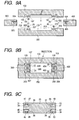
- Figs. 8A and 8B are illustrations showing a state molding the lens driving apparatus with the lead frame
- Figs. 9A to 9C are sectional views illustrating operations of the manufacturing apparatus.
- the manufacturing apparatus is provided with a mold comprising a top movable mold 100, a bottom movable mold 200, a left movable mold 300 and a right movable mold 400.
- a pair of metal lead frames 500, 600 punched are transferred to a predetermined direction Z while maintaining a predetermined distance, and it is intended to mold the substrate 25 with resin relative to the metal lead frames 500, 600 by the movable molds 100, 200, 300, 400 disposed perpendicularly to the transfer direction Z.
- elastic wires 27, 29, supporting portions 27 L , 27 R , 29 L , 29 R for molding the lens holder 26 and the substrate 25 with resin in both ends (left and right sides in the drawing) of these elastic wires 27, 29, and a plurality of positioning holes HU for positioning the top movable mold 100 are previously formed in the metal lead frame 500 by punching. Further, the belt-shaped metal lead frame 500 shown in Fig. 5 is formed by continuously performing the punching corresponding to one lens driving apparatus in a longitudinal direction of the metal lead frame 500.
- elastic wires 28, 30, supporting portions 28 L , 28 R , 30 L , 30 R for molding the lens holder 26 and the substrate 25 with resin in both ends (left and right sides in the drawing) of these elastic wires 28, 30, and a plurality of positioning holes HL for positioning the bottom movable mold 200 are also previously formed in the metal lead frame 600 by punching, and the belt-shaped metal lead frame 600 shown in Fig. 5 is formed by continuously performing the punching corresponding to one lens driving apparatus in a longitudinal direction of the metal lead frame 600.
- These metal lead frames 500, 600 are transferred to the transfer direction Z while maintaining the lead frames in parallel at a constant opposed distance, and the substrate 25 is molded with resin by the movable molds 100, 200, 300, 400 at predetermined timing.
- the substrate 25 is removed from the movable molds 100, 200, 300, 400, as shown in a plan view of Fig. 8A and a side view of Fig. 8B, the lead frames 500, 600 of both sides of the substrate 25 and the lens holder 26 are cut along virtual lines CUT1, CUT2 and unnecessary portions of the lead frames 500, 600 are eliminated and thereby, an intermediate product of the lens driving apparatus is manufactured. Further, it is intended to complete the lens driving apparatus by mounting the magnetic circuit unit (see Fig. 2) while mounting the objective lens 52 (see Fig. 1) in the lens mounting portion 51 of the lens holder 26.
- each movable mold 100, 200, 300, 400 will be described with reference to Fig. 4. Cavities with the substantially same shape are formed on opposed surfaces of the top movable mold 100 and the bottom movable mold 200.
- an approximately rectangular depression 202 for forming a body portion of the substrate 25 is formed.
- depressions 203, 204 ranging to the rear side of the depression 202
- depressions 205, 206 ranging to the depressions 203, 204 and extending to the front side (the side of the lens holder 26) are formed.
- Slit grooves 209, 210 extending from the front end of the bottom movable mold 200 to the depressions 203, 204 are formed on respective top surfaces of long lengths of projections (hereinafter called line projection) 207, 208 between the depression 202 and the depressions 205, 206. Further, slit grooves 211, 212 extending to the slit grooves 209, 210 are provided extending to the rear end of the bottom movable mold 200 through the depressions 203, 204.
- the slit grooves 209, 211 are provided for fitting the elastic wire 28 formed in the lead frame 600 by punching, and the slit grooves 210, 212 are provided for fitting the elastic wire 30 formed in the lead frame 600 by punching, and the depressions 202, 203, 204, 205, 206 are provided for being filled with synthetic resin.
- slit grooves 109, 110 (corresponding to the slit grooves 209, 210) formed on the top movable mold 100 is shown in Fig. 4, but the top movable mold 100 also has a structure similar to that of the bottom movable mold 200.
- the left movable mold 300 and the right movable mold 400 have a symmetrical structure, respectively.
- These left and right movable molds 300, 400 respectively, have body portions 301, 401 with the approximately same thickness W' as a thickness W of the substrate 25, and rectangular depressions 302, 402 for defining a depth and a width of the substrate 25 are formed in the top portions of the body portions 301, 401.
- plate-shaped rectangular regulating projections 304, 305 opposed each other are formed in a deep portion of the depression 302 of the left movable mold 300, and a rectangular notch 307 is formed in the rear end of the regulating projections 304, 305.
- plate-shaped rectangular regulating projections 404, 405 opposed each other are formed in a deep portion of the depression 402 of the right movable mold 400, and a rectangular notch 407 is formed in the rear end of the regulating projections 404, 405.
- the regulating projection 405 is not shown, but the regulating projection 405 is provided below the regulating projection 404 with them opposed.
- Figs. 9A and 9B are vertical sectional views of the movable molds 100, 200, 300, 400 shown in Fig. 1 and indicate cross sections taken on a virtual plane perpendicular to the line projections 209, 210 of the bottom movable mold 200. Also, Fig. 9C indicates a cross section of the substrate 25 in the virtual plane.
- the lead frames 500, 600 are transferred in the transfer direction Z and are transferred to a position where the elastic wires 27, 28, 29, 30 formed in the lead frames 500, 600 oppose the movable molds 100, 200, 300, 400.
- the elastic wires 27, 29 become opposed to the slit grooves 109, 110 of the top movable mold 100
- the elastic wires 28, 30 become opposed to the slit grooves 209, 210 of the bottom movable mold 200, respectively.
- the left movable mold 300 and the right movable mold 400 are inserted to a predetermined position between the lead frames 500, 600, and further the top movable mold 100 and the bottom movable mold 200 are moved to a predetermined position of the side of the lead frames 500, 600 and thereby, these movable molds 100, 200, 300, 400 are combined.
- the elastic wires 27, 29 are fitted into the slit grooves 109, 110 of the top movable mold 100, and the elastic wires 28, 30 are fitted into the slit grooves 209, 210 of the bottom movable mold 200.
- the regulating projections 304, 305, 404, 405 of the left and right movable molds 300, 400 are inserted to a position of the edges of the depression 102 of the top movable mold 100 and the depression 202 of the bottom movable mold 200.
- the regulating projection 304 blocks the depression 105 of the top movable mold 100 and the depression 107 into which the elastic wire 27 is fitted
- the regulating projection 305 blocks the depression 205 of the bottom movable mold 200 and the depression 207 into which the elastic wire 28 is fitted
- the regulating projection 404 blocks the depression 106 of the top movable mold 100 and the depression 210 into which the elastic wire 30 is fitted.
- synthetic resin is injected from a synthetic resin injection hole (omission of reference sign) provided in a predetermined portion of the top movable mold 100, and the cavities formed by the movable molds 100, 200, 300, 400 are filled with the synthetic resin.
- the movable molds 100, 200, 300, 400 are separated.
- the substrate 25 is integrally molded with the elastic wires 27, 28, 29, 30.
- the rear ends 47, 48, 49, 50 are formed in the four corners of the substrate 25 by the synthetic resin with which the depressions 203, 204 of the bottom movable mold 200 and the depressions (corresponding to the depressions 203, 204) of the top movable mold 100 shown in Fig. 4 are filled, and further the elastic wires 27, 28, 29, 30 are buried into these rear ends 47, 48, 49, 50 and are integrated.
- long lengths of the projection portions 31, 33, 32, 34 are molded in the four corners of the substrate 25 by the synthetic resin with which the depressions 105, 106 formed in the top movable mold 100 and the depressions 205, 206 formed in the bottom movable mold 200 are filled.
- the depression 105 is filled with the synthetic resin in a state that the elastic wire 27 is fitted into the slit groove 109 of the line projection 107 of the top movable mold 100 and the depression 105 is blocked with the line projection 107 and the regulating projection 304 of the left movable mold 300.
- the depression stepped portion 35 opposed to the projection portion 31 and the gap 39 defined by the projection portion 31 and the depression stepped portion 35 are formed in the substrate 25 and further, the elastic wire 27 is provided within the gap 39 with the elastic wire floated.
- the residual projection portions 32, 33, 34 and the depression stepped portions 35, 36, 37, 38 are formed in like manner, and the elastic wires 28, 29, 30 are provided within the gaps 40, 41, 42 with the elastic wires floated, respectively.
- the gaps 39, 40, 41, 42 are filled with the ultraviolet cure resins 43, 44, 45, 46 acting as a damping material to the resins.
- the narrow gaps 39, 40, 41, 42 which are defined by the projection portions 31, 32, 33, 34 and the depression stepped portions 35, 36, 37, 38 and interpose the elastic wires 27, 28, 29, 30 are filled with the ultraviolet cure resins 43, 44, 45, 46, so that surface tension occurs.
- the resins are cured without liquid sagging out of the gaps 39, 40, 41, 42 due to the occurrence of the surface tension.
- the lens driving apparatus is completed by mounting the magnetic circuit unit while mounting the objective lens 52 in the lens holder 26 of the intermediate product.
- the column-shaped projection portions 31, 32, 33, 34 are integrally molded in the four corners of the substrate 25, and the gaps 39, 40, 41, 42 formed between the projection portions and the depression stepped portions 35, 36, 37, 38 opposed to these projection portions 31, 32, 33, 34 are filled with the ultraviolet cure resins 43, 44, 45, 46 to cure the resins in a state of cantilevering the elastic wires 27, 28, 29, 30, so that the so-called liquid sagging of the ultraviolet cure resins 43, 44, 45, 46 can be prevented.
- the gaps 39, 40, 41, 42 for filling of the ultraviolet cure resins 43, 44, 45, 46 are formed by integrally molding the column-shaped projection portions 31, 32, 33, 34 with the substrate 25 using the movable molds 100, 200, 300, 400, so that the conventional opposed pieces 12, 13 are eliminated.
- the number of manufacturing steps as well as the number of parts can be reduced.
- miniaturization and weight reduction of the lens driving apparatus can be achieved.
- column-shaped projection portions 31, 32, 33, 34 are integrally molded in the four corners of the substrate 25 and the elastic wires 27, 28, 29, 30 are fastened using the ultraviolet cure resins 43, 44, 45, 46
- column-shaped projection portions similar to the column-shaped projection portions 31, 32, 33, 34 may be integrally molded in four corners of the lens holder 26 and gaps formed between their projection portions and a body portion of the lens holder 26 may be filled with the ultraviolet cure resins to cure the resins in a state of cantilevering the top ends of the elastic wires 27, 28, 29, 30.
- the elastic wires 27, 28, 29, 30 may be fixed in the lens holder 26 and further the gaps may be filled with the ultraviolet cure resins. According to such a configuration, the elastic wires 27, 28, 29, 30 can be damped by the ultraviolet cure resins filled in the side of the lens holder 26.
- the elastic wires 27, 28, 29, 30 may be damped by performing the filling of the ultraviolet cure resins in both of the lens holder 26 and the substrate 25.
- the ultraviolet cure resins are used as a damping material in the embodiment, but other cure resins, for example, thermoplastic resins may be used.
- gaps are integrally molded in a base of the substrate or a base of the lens holder and also, elastic wires are integrated with the base and further, the elastic wires are surrounded with a damping material by filling these gaps with the damping material, so that the number of parts and the number of manufacturing steps can be reduced while preventing liquid sagging of the damping material.
Landscapes
- Physics & Mathematics (AREA)
- Optics & Photonics (AREA)
- Optical Recording Or Reproduction (AREA)
- Optical Head (AREA)
- Casting Or Compression Moulding Of Plastics Or The Like (AREA)
Abstract
Description
Claims (13)
- A lens driving apparatus comprising:a lens holder for holding an objective lens, anda substrate which supports said lens holder through elastic members and is molded with resin, whereinsaid elastic members are integrally supported in the substrate in the case of the resin molding and are provided within gaps molded in said substrate with the gaps ranging to said integrally supported portions and are buried in a damping material with which the gaps are filled.
- The lens driving apparatus as claimed in claim 1, wherein
the gaps are formed by depression portions and projection portions opposed one another molded in the proximity of said elastic members in the case of the resin molding. - A lens driving apparatus comprising:a lens holder which holds an objective lens and is molded with resin, anda substrate for supporting said lens holder through elastic members, whereinsaid elastic members are integrally supported in said lens holder in the case of the resin molding and are provided within gaps molded in said lens holder with the gaps ranging to said integrally supported portions and are buried in a damping material with which the gaps are filled.
- The lens driving apparatus as claimed in claim 3, wherein
the gaps are formed by depression portions and projection portions opposed one another molded in the proximity of said elastic members in the case of the resin molding. - The lens driving apparatus as claimed in claim 2 or 4, wherein
the depression portions and projection portions are molded in a long shape along a longitudinal direction of said elastic members. - The lens driving apparatus as claimed in claim 5, wherein
the depression portions and projection portions are molded by a mold for resin molding. - The lens driving apparatus as in one of claims 1 to 5, wherein
said damping material is ultraviolet cure resin. - A manufacturing apparatus of a lens driving apparatus,said lens driving apparatus comprising:a lens holder for holding an objective lens, anda substrate for supporting said lens holder through elastic members,said manufacturing apparatus comprising:a mold on which cavities having a first depression for molding a base of said substrate, a projection adjacent to the first depression, and a second depression adjacent to the projection and partially ranging to the first depression are formed, whereinby filling the cavities of the mold with synthetic resin with said elastic members stretched between the projection of the mold and the ranging portion of the first and second depressions, said elastic members are supported in the base molded by the synthetic resin with which the ranging portion is filled and are provided within gaps formed by the projection, and thereafter are buried in a damping material by filling the gaps with said damping material.
- A manufacturing apparatus of a lens driving apparatus,said lens driving apparatus comprising:a lens holder for holding an objective lens, anda substrate for supporting said lens holder through elastic members,said manufacturing apparatus comprising:a mold on which cavities having a first depression for molding a base of said lens holder, a projection adjacent to the first depression, and a second depression adjacent to the projection and partially ranging to the first depression are formed, whereinby filling the cavities of the mold with synthetic resin with said elastic members stretched between the projection of the mold and the ranging portion of the first and second depressions, said elastic members are supported in the base molded by the synthetic resin with which the ranging portion is filled and are provided within gaps formed by the projection, and thereafter are buried in a damping material by filling the gaps with said damping material.
- The manufacturing apparatus of a lens driving apparatus as claimed in claim 8 or 9, wherein
said mold comprises:a first and a second molds forming the first and second depressions and a first projection by mutual combinations, anda third mold having a first regulating projection inserted in contact with the top of the first projection while being inserted between said first and said second molds and blocking the opening end of the second depression, andsaid projection molded in the second depression by filling the cavities with said synthetic resin is formed opposed to the base through a gap formed by said first projection and said first regulating projection. - A manufacturing apparatus of a lens driving apparatus,by filling the first and second cavities for resin molding with synthetic resin with said elastic members stretched between the first projection of said mold and the ranging portion of the first and second depressions and between said second projection and the ranging portion of the third and fourth depressions,said lens driving apparatus comprising:a lens holder for holding an objective lens, anda substrate for supporting said lens holder through elastic members,said manufacturing apparatus comprising:a mold comprising:first cavities for resin molding having a first depression for molding a base of the substrate, a first projection adjacent to the first depression, and a second depression adjacent to the first projection and partially ranging to the first depression, andsecond cavities for resin molding having a third depression for molding a base of the lens holder, a second projection adjacent to the third depression, and a fourth depression adjacent to the second projection and partially ranging to the third depression, wherein
said elastic members are supported in both the bases of said substrate and said lens holder molded by the synthetic resin with which the ranging portion is filled and are provided within each gap formed by the first and second projections, and thereafter are buried in a damping material by filling each the gap with said damping material. - A manufacturing method of a lens driving apparatus,said lens driving apparatus comprising:a lens holder for holding an objective lens, anda substrate for supporting said lens holder through elastic members,said manufacturing method comprising:a first step of fitting said elastic members into a mold on which cavities having a first depression for molding a base of said substrate, a projection adjacent to the first depression, and a second depression adjacent to said projection and partially ranging to the first depression are formed with said elastic members stretched between said projection and said ranging portion of the first and second depressions,a second step of integrally supporting said elastic members in the base molded by the synthetic resin with which the ranging portion is filled and providing said elastic members within gaps formed by said projection between the first and second depressions by filling the cavities of said mold with synthetic resin, anda third step of burying said elastic members in a damping material by filling the gaps with said damping material after separating said mold.
- A manufacturing method of a lens driving apparatus,14. The manufacturing method of a lens driving apparatus as claimed in claim 12 or 13, whereinsaid lens driving apparatus comprising:a lens holder for holding an objective lens, anda substrate for supporting said lens holder through elastic members,said manufacturing method comprising:a first step of fitting said elastic members into a mold on which cavities having a first depression for molding a base of said lens holder, a projection adjacent to the first depression, and a second depression adjacent to the projection and partially ranging to the first depression are formed with said elastic members stretched between said projection and the ranging portion of the first and second depressions,a second step of integrally supporting said elastic members in the base molded by the synthetic resin with which the ranging portion is filled and providing said elastic members within gaps formed by said projection between the first and second depressions by filling the cavities of said mold with synthetic resin, anda third step of burying the elastic members in a damping material by filling the gaps with said damping material after separating said mold.
ultraviolet cure resin is filled as said damping material in the third step.
Applications Claiming Priority (2)
| Application Number | Priority Date | Filing Date | Title |
|---|---|---|---|
| JP33179899 | 1999-11-22 | ||
| JP33179899A JP3981509B2 (en) | 1999-11-22 | 1999-11-22 | LENS DRIVE DEVICE, ITS MANUFACTURING DEVICE, AND LENS DRIVE DEVICE MANUFACTURING METHOD |
Publications (3)
| Publication Number | Publication Date |
|---|---|
| EP1107035A2 true EP1107035A2 (en) | 2001-06-13 |
| EP1107035A3 EP1107035A3 (en) | 2002-03-27 |
| EP1107035B1 EP1107035B1 (en) | 2006-03-08 |
Family
ID=18247769
Family Applications (1)
| Application Number | Title | Priority Date | Filing Date |
|---|---|---|---|
| EP00309955A Expired - Lifetime EP1107035B1 (en) | 1999-11-22 | 2000-11-09 | Lens driving device, and apparatus for and method of manufacturing the device |
Country Status (5)
| Country | Link |
|---|---|
| US (1) | US6462892B1 (en) |
| EP (1) | EP1107035B1 (en) |
| JP (1) | JP3981509B2 (en) |
| CN (1) | CN1174388C (en) |
| DE (1) | DE60026465T2 (en) |
Cited By (1)
| Publication number | Priority date | Publication date | Assignee | Title |
|---|---|---|---|---|
| EP1511020A4 (en) * | 2002-05-17 | 2007-05-02 | Matsushita Electric Industrial Co Ltd | LENS PILOT LENS |
Families Citing this family (12)
| Publication number | Priority date | Publication date | Assignee | Title |
|---|---|---|---|---|
| KR100547360B1 (en) * | 2003-09-16 | 2006-01-26 | 삼성전기주식회사 | Bobbin with integrated winding coil, optical pick-up actuator using the same and method for manufacturing same |
| JP2005127914A (en) * | 2003-10-24 | 2005-05-19 | Fujinon Corp | Interferometer device lens mount |
| US7247356B2 (en) * | 2003-11-26 | 2007-07-24 | E. I. Du Pont De Nemours And Company | Privacy screen for a display |
| US7052746B2 (en) * | 2003-11-26 | 2006-05-30 | E. I. Du Pont De Nemour And Company | Privacy screen for a display |
| US7201955B2 (en) * | 2003-11-26 | 2007-04-10 | E. I. Du Pont De Nemours And Company | Privacy screen for a display |
| JP2005251295A (en) * | 2004-03-04 | 2005-09-15 | Funai Electric Co Ltd | Optical pickup |
| US20080171168A1 (en) * | 2004-08-20 | 2008-07-17 | Takehiro Matsuda | Component Molding Method, Resin Component And Component Molding Die |
| US7170680B2 (en) * | 2005-01-06 | 2007-01-30 | E. I. Du Pont De Nemours And Company | Privacy screen for a display |
| US7484378B2 (en) * | 2005-05-10 | 2009-02-03 | Emp Advanced Development, Llc | Cooling system and method for cooling a heat producing system |
| KR101452960B1 (en) * | 2013-04-29 | 2014-10-22 | 도시바삼성스토리지테크놀러지코리아 주식회사 | Object lens driving unit and optical disc drive using the same |
| TWI789489B (en) * | 2018-02-06 | 2023-01-11 | 日商三美電機股份有限公司 | Camera actuator, camera module, and camera-mounted device |
| JP7007574B2 (en) * | 2018-02-06 | 2022-02-10 | ミツミ電機株式会社 | Camera actuators, camera modules, and camera-mounted devices |
Family Cites Families (15)
| Publication number | Priority date | Publication date | Assignee | Title |
|---|---|---|---|---|
| US4794581A (en) * | 1987-06-25 | 1988-12-27 | International Business Machines Corporation | Lens support system enabling focussing and tracking motions employing a unitary lens holder |
| JP2684762B2 (en) * | 1989-04-20 | 1997-12-03 | ソニー株式会社 | Objective lens drive |
| JP2978588B2 (en) * | 1991-05-27 | 1999-11-15 | パイオニア株式会社 | Method for manufacturing lens driving device in optical pickup |
| JP3411603B2 (en) * | 1992-07-28 | 2003-06-03 | ペンタックス株式会社 | Objective lens electromagnetic drive for optical information recording / reproducing device |
| US5724337A (en) * | 1993-10-29 | 1998-03-03 | Tdk Corporation | Optical pickup with a compact design |
| JPH08329496A (en) * | 1995-05-31 | 1996-12-13 | Mitsumi Electric Co Ltd | Optical head |
| JPH10289455A (en) * | 1997-02-12 | 1998-10-27 | Tdk Corp | Objective lens driving device and its production |
| US6160771A (en) * | 1997-02-12 | 2000-12-12 | Tdk Corporation | Objective lens drive device and method of manufacturing the same |
| JPH10269598A (en) * | 1997-03-25 | 1998-10-09 | Tdk Corp | Objective lens driving device and its manufacture |
| JPH10312558A (en) * | 1997-05-14 | 1998-11-24 | Mitsumi Electric Co Ltd | Optical pickup device |
| JPH11191231A (en) * | 1997-12-26 | 1999-07-13 | Nhk Spring Co Ltd | Objective lens actuator |
| JPH11232670A (en) * | 1998-02-17 | 1999-08-27 | Alps Electric Co Ltd | Optical pickup |
| US6377521B1 (en) * | 1998-08-14 | 2002-04-23 | Sony Corporation | Biaxial actuator, optical part and optical disk device |
| JP2000215483A (en) * | 1999-01-27 | 2000-08-04 | Mitsumi Electric Co Ltd | Optical pickup and method of assembling the same |
| US6166867A (en) * | 1999-09-13 | 2000-12-26 | Acute Applied Technologies | Objective lens holder |
-
1999
- 1999-11-22 JP JP33179899A patent/JP3981509B2/en not_active Expired - Fee Related
-
2000
- 2000-11-01 CN CNB001328042A patent/CN1174388C/en not_active Expired - Fee Related
- 2000-11-09 EP EP00309955A patent/EP1107035B1/en not_active Expired - Lifetime
- 2000-11-09 DE DE60026465T patent/DE60026465T2/en not_active Expired - Fee Related
- 2000-11-22 US US09/717,341 patent/US6462892B1/en not_active Expired - Fee Related
Cited By (1)
| Publication number | Priority date | Publication date | Assignee | Title |
|---|---|---|---|---|
| EP1511020A4 (en) * | 2002-05-17 | 2007-05-02 | Matsushita Electric Industrial Co Ltd | LENS PILOT LENS |
Also Published As
| Publication number | Publication date |
|---|---|
| US6462892B1 (en) | 2002-10-08 |
| JP3981509B2 (en) | 2007-09-26 |
| CN1297226A (en) | 2001-05-30 |
| EP1107035B1 (en) | 2006-03-08 |
| DE60026465T2 (en) | 2006-09-28 |
| CN1174388C (en) | 2004-11-03 |
| EP1107035A3 (en) | 2002-03-27 |
| JP2001148131A (en) | 2001-05-29 |
| DE60026465D1 (en) | 2006-05-04 |
Similar Documents
| Publication | Publication Date | Title |
|---|---|---|
| US6462892B1 (en) | Lens driving apparatus, apparatus and method of manufacturing the lens driving apparatus | |
| JP3888821B2 (en) | Pickup device and manufacturing method thereof | |
| EP1124226B1 (en) | Lens drive device and method for manufacturing the same | |
| US6160771A (en) | Objective lens drive device and method of manufacturing the same | |
| JP3995857B2 (en) | Lens drive device for disc player | |
| US5892629A (en) | Objective lens actuator | |
| JP2001229557A (en) | Lens driving device for disk player and printed board coil for lens driving device for disk player | |
| US6580569B2 (en) | Optical pickup assembly | |
| EP1486992B1 (en) | Actuator with molded coil device for disc drive | |
| US5850313A (en) | Objective lens driving device and a method for manufacturing the same | |
| US7014798B2 (en) | Method for manufacturing an optical pickup | |
| KR100310063B1 (en) | Optical pick-up | |
| US7092173B2 (en) | Objective lens drive device, optical pickup device, and disk drive device | |
| EP0562646B1 (en) | Electro-magnetic actuator and optical disk | |
| JP3407483B2 (en) | Manufacturing method of twin axis actuator | |
| KR100238033B1 (en) | Damper of optical pickup actuator | |
| US7397732B2 (en) | Objective lens driving apparatus and optical disc apparatus | |
| JP2659933B2 (en) | Optical head device | |
| US20080171168A1 (en) | Component Molding Method, Resin Component And Component Molding Die | |
| JP3933159B2 (en) | Optical pickup | |
| JPH09282690A (en) | Movable member for lens driving device | |
| JP3500293B2 (en) | Manufacturing method of optical pickup | |
| KR100326827B1 (en) | Optical pick-up | |
| JPH10289455A (en) | Objective lens driving device and its production | |
| JPH05174352A (en) | Ceramic slider for magnetic disk head |
Legal Events
| Date | Code | Title | Description |
|---|---|---|---|
| PUAI | Public reference made under article 153(3) epc to a published international application that has entered the european phase |
Free format text: ORIGINAL CODE: 0009012 |
|
| AK | Designated contracting states |
Kind code of ref document: A2 Designated state(s): DE FR GB Kind code of ref document: A2 Designated state(s): AT BE CH CY DE DK ES FI FR GB GR IE IT LI LU MC NL PT SE TR |
|
| AX | Request for extension of the european patent |
Free format text: AL;LT;LV;MK;RO;SI |
|
| PUAL | Search report despatched |
Free format text: ORIGINAL CODE: 0009013 |
|
| AK | Designated contracting states |
Kind code of ref document: A3 Designated state(s): AT BE CH CY DE DK ES FI FR GB GR IE IT LI LU MC NL PT SE TR |
|
| AX | Request for extension of the european patent |
Free format text: AL;LT;LV;MK;RO;SI |
|
| RIC1 | Information provided on ipc code assigned before grant |
Free format text: 7G 02B 7/04 A, 7B 29C 45/00 B, 7G 11B 7/22 B, 7G 11B 7/09 B |
|
| 17P | Request for examination filed |
Effective date: 20020906 |
|
| AKX | Designation fees paid |
Free format text: DE FR GB |
|
| 17Q | First examination report despatched |
Effective date: 20030224 |
|
| GRAP | Despatch of communication of intention to grant a patent |
Free format text: ORIGINAL CODE: EPIDOSNIGR1 |
|
| GRAS | Grant fee paid |
Free format text: ORIGINAL CODE: EPIDOSNIGR3 |
|
| GRAA | (expected) grant |
Free format text: ORIGINAL CODE: 0009210 |
|
| AK | Designated contracting states |
Kind code of ref document: B1 Designated state(s): DE FR GB |
|
| REG | Reference to a national code |
Ref country code: GB Ref legal event code: FG4D |
|
| REF | Corresponds to: |
Ref document number: 60026465 Country of ref document: DE Date of ref document: 20060504 Kind code of ref document: P |
|
| ET | Fr: translation filed | ||
| PLBE | No opposition filed within time limit |
Free format text: ORIGINAL CODE: 0009261 |
|
| STAA | Information on the status of an ep patent application or granted ep patent |
Free format text: STATUS: NO OPPOSITION FILED WITHIN TIME LIMIT |
|
| 26N | No opposition filed |
Effective date: 20061211 |
|
| PGFP | Annual fee paid to national office [announced via postgrant information from national office to epo] |
Ref country code: DE Payment date: 20071101 Year of fee payment: 8 |
|
| PGFP | Annual fee paid to national office [announced via postgrant information from national office to epo] |
Ref country code: FR Payment date: 20071108 Year of fee payment: 8 Ref country code: GB Payment date: 20071107 Year of fee payment: 8 |
|
| GBPC | Gb: european patent ceased through non-payment of renewal fee |
Effective date: 20081109 |
|
| REG | Reference to a national code |
Ref country code: FR Ref legal event code: ST Effective date: 20090731 |
|
| PG25 | Lapsed in a contracting state [announced via postgrant information from national office to epo] |
Ref country code: DE Free format text: LAPSE BECAUSE OF NON-PAYMENT OF DUE FEES Effective date: 20090603 |
|
| PG25 | Lapsed in a contracting state [announced via postgrant information from national office to epo] |
Ref country code: GB Free format text: LAPSE BECAUSE OF NON-PAYMENT OF DUE FEES Effective date: 20081109 |
|
| PG25 | Lapsed in a contracting state [announced via postgrant information from national office to epo] |
Ref country code: FR Free format text: LAPSE BECAUSE OF NON-PAYMENT OF DUE FEES Effective date: 20081130 |