EP1107032A1 - Fiber optic connector module - Google Patents
Fiber optic connector module Download PDFInfo
- Publication number
- EP1107032A1 EP1107032A1 EP00126669A EP00126669A EP1107032A1 EP 1107032 A1 EP1107032 A1 EP 1107032A1 EP 00126669 A EP00126669 A EP 00126669A EP 00126669 A EP00126669 A EP 00126669A EP 1107032 A1 EP1107032 A1 EP 1107032A1
- Authority
- EP
- European Patent Office
- Prior art keywords
- ferrule
- fiber optic
- optic connector
- housing
- connector module
- Prior art date
- Legal status (The legal status is an assumption and is not a legal conclusion. Google has not performed a legal analysis and makes no representation as to the accuracy of the status listed.)
- Granted
Links
- 239000000835 fiber Substances 0.000 title claims abstract description 43
- 230000013011 mating Effects 0.000 claims abstract description 28
- 239000013307 optical fiber Substances 0.000 claims abstract description 14
- 238000003780 insertion Methods 0.000 claims description 9
- 230000037431 insertion Effects 0.000 claims description 9
- 239000000463 material Substances 0.000 claims description 7
- 239000004033 plastic Substances 0.000 claims description 4
- 230000000295 complement effect Effects 0.000 claims description 3
- 230000000712 assembly Effects 0.000 description 9
- 238000000429 assembly Methods 0.000 description 9
- 238000000034 method Methods 0.000 description 4
- 239000000758 substrate Substances 0.000 description 4
- 230000005540 biological transmission Effects 0.000 description 3
- 239000002991 molded plastic Substances 0.000 description 3
- 239000000919 ceramic Substances 0.000 description 1
- 238000004891 communication Methods 0.000 description 1
- 239000003989 dielectric material Substances 0.000 description 1
- 239000000428 dust Substances 0.000 description 1
- 238000005192 partition Methods 0.000 description 1
- 230000002093 peripheral effect Effects 0.000 description 1
- 239000007787 solid Substances 0.000 description 1
Images









Classifications
-
- G—PHYSICS
- G02—OPTICS
- G02B—OPTICAL ELEMENTS, SYSTEMS OR APPARATUS
- G02B6/00—Light guides; Structural details of arrangements comprising light guides and other optical elements, e.g. couplings
- G02B6/24—Coupling light guides
- G02B6/36—Mechanical coupling means
-
- G—PHYSICS
- G02—OPTICS
- G02B—OPTICAL ELEMENTS, SYSTEMS OR APPARATUS
- G02B6/00—Light guides; Structural details of arrangements comprising light guides and other optical elements, e.g. couplings
- G02B6/24—Coupling light guides
- G02B6/36—Mechanical coupling means
- G02B6/38—Mechanical coupling means having fibre to fibre mating means
- G02B6/3807—Dismountable connectors, i.e. comprising plugs
- G02B6/389—Dismountable connectors, i.e. comprising plugs characterised by the method of fastening connecting plugs and sockets, e.g. screw- or nut-lock, snap-in, bayonet type
- G02B6/3893—Push-pull type, e.g. snap-in, push-on
-
- G—PHYSICS
- G02—OPTICS
- G02B—OPTICAL ELEMENTS, SYSTEMS OR APPARATUS
- G02B6/00—Light guides; Structural details of arrangements comprising light guides and other optical elements, e.g. couplings
- G02B6/24—Coupling light guides
- G02B6/36—Mechanical coupling means
- G02B6/38—Mechanical coupling means having fibre to fibre mating means
- G02B6/3807—Dismountable connectors, i.e. comprising plugs
- G02B6/381—Dismountable connectors, i.e. comprising plugs of the ferrule type, e.g. fibre ends embedded in ferrules, connecting a pair of fibres
- G02B6/3818—Dismountable connectors, i.e. comprising plugs of the ferrule type, e.g. fibre ends embedded in ferrules, connecting a pair of fibres of a low-reflection-loss type
- G02B6/3821—Dismountable connectors, i.e. comprising plugs of the ferrule type, e.g. fibre ends embedded in ferrules, connecting a pair of fibres of a low-reflection-loss type with axial spring biasing or loading means
-
- G—PHYSICS
- G02—OPTICS
- G02B—OPTICAL ELEMENTS, SYSTEMS OR APPARATUS
- G02B6/00—Light guides; Structural details of arrangements comprising light guides and other optical elements, e.g. couplings
- G02B6/24—Coupling light guides
- G02B6/36—Mechanical coupling means
- G02B6/38—Mechanical coupling means having fibre to fibre mating means
- G02B6/3807—Dismountable connectors, i.e. comprising plugs
- G02B6/3869—Mounting ferrules to connector body, i.e. plugs
-
- G—PHYSICS
- G02—OPTICS
- G02B—OPTICAL ELEMENTS, SYSTEMS OR APPARATUS
- G02B6/00—Light guides; Structural details of arrangements comprising light guides and other optical elements, e.g. couplings
- G02B6/24—Coupling light guides
- G02B6/36—Mechanical coupling means
- G02B6/38—Mechanical coupling means having fibre to fibre mating means
- G02B6/3807—Dismountable connectors, i.e. comprising plugs
- G02B6/3873—Connectors using guide surfaces for aligning ferrule ends, e.g. tubes, sleeves, V-grooves, rods, pins, balls
- G02B6/3874—Connectors using guide surfaces for aligning ferrule ends, e.g. tubes, sleeves, V-grooves, rods, pins, balls using tubes, sleeves to align ferrules
- G02B6/3878—Connectors using guide surfaces for aligning ferrule ends, e.g. tubes, sleeves, V-grooves, rods, pins, balls using tubes, sleeves to align ferrules comprising a plurality of ferrules, branching and break-out means
-
- G—PHYSICS
- G02—OPTICS
- G02B—OPTICAL ELEMENTS, SYSTEMS OR APPARATUS
- G02B6/00—Light guides; Structural details of arrangements comprising light guides and other optical elements, e.g. couplings
- G02B6/24—Coupling light guides
- G02B6/36—Mechanical coupling means
- G02B6/38—Mechanical coupling means having fibre to fibre mating means
- G02B6/3807—Dismountable connectors, i.e. comprising plugs
- G02B6/381—Dismountable connectors, i.e. comprising plugs of the ferrule type, e.g. fibre ends embedded in ferrules, connecting a pair of fibres
- G02B6/3825—Dismountable connectors, i.e. comprising plugs of the ferrule type, e.g. fibre ends embedded in ferrules, connecting a pair of fibres with an intermediate part, e.g. adapter, receptacle, linking two plugs
-
- G—PHYSICS
- G02—OPTICS
- G02B—OPTICAL ELEMENTS, SYSTEMS OR APPARATUS
- G02B6/00—Light guides; Structural details of arrangements comprising light guides and other optical elements, e.g. couplings
- G02B6/24—Coupling light guides
- G02B6/36—Mechanical coupling means
- G02B6/38—Mechanical coupling means having fibre to fibre mating means
- G02B6/3807—Dismountable connectors, i.e. comprising plugs
- G02B6/3897—Connectors fixed to housings, casing, frames or circuit boards
-
- G—PHYSICS
- G02—OPTICS
- G02B—OPTICAL ELEMENTS, SYSTEMS OR APPARATUS
- G02B6/00—Light guides; Structural details of arrangements comprising light guides and other optical elements, e.g. couplings
- G02B6/24—Coupling light guides
- G02B6/36—Mechanical coupling means
- G02B6/38—Mechanical coupling means having fibre to fibre mating means
- G02B6/3807—Dismountable connectors, i.e. comprising plugs
- G02B6/3898—Tools, e.g. handheld; Tuning wrenches; Jigs used with connectors, e.g. for extracting, removing or inserting in a panel, for engaging or coupling connectors, for assembling or disassembling components within the connector, for applying clips to hold two connectors together or for crimping
Definitions
- This invention generally relates to the art of fiber optic transmission and, particularly, to fiber optic connector module.
- a typical fiber optic connector includes a ferrule which mounts and centers an optical fiber or fibers within the connector.
- the ferrule may be fabricated of such material as ceramic.
- a ferrule holder or other housing component of the connector embraces the ferrule and may be fabricated of such material as molded plastic.
- a spring may be disposed within the housing or ferrule holder such that the ferrule is yieldably biased forwardly for engaging another fiber-mounting ferrule of a mating connecting device.
- a pair of fiber optic connectors or a connector and another optical fiber transmission device often are mated in an adapter which centers the fibers to provide low insertion losses.
- the adapter couples the connectors together so that their encapsulated fibers connect end-to-end.
- the adapter may be an in-line component, or the adapter can be designed for mounting in an opening in a panel, backplane, circuit board or the like.
- An object, therefore, of the invention is to provide a new and improved connector assembly, particularly a fiber optic connector module.
- the module includes a ferrule terminated to at least one optical fiber.
- the ferrule is mounted in a manually manipulatable housing which includes a front portion encapsulating the ferrule and a rear portion extending rearwardly of the front portion for manual grasping by an operator.
- the front portion has an open front end from which a mating end of the ferrule projects.
- the optical fiber extends through an open rear end of the housing.
- the rear portion of the housing is formed by a pair of laterally spaced arms graspable between an operator's fingers.
- the outsides of the arms have serrations to facilitate manual grasping thereof.
- the insides of the arms have guide channels for guiding insertion of the ferrule into the open rear end of the front portion of the housing.
- latch means on the outside of the housing for latching the module in a complementary receptacle.
- Flexible latch arms are provided at the front of the housing engageable with opposite sides of a flange of the ferrule for holding the ferrule encapsulated within the front portion of the housing.
- the housing is a one-piece structure unitarily molded of plastic material.
- a mating connector assembly generally designated 24, which includes a backplane connector assembly, generally designated 26, mateable with a daughterboard connector assembly, generally designated 28.
- the backplane connector assembly is mounted in an aperture 30 in a substrate, panel or backplane which, in the preferred embodiment, is a printed circuit board.
- backplane 32 can be considered the "motherboard” herein.
- the daughterboard connector assembly is mounted on a top surface of a second printed circuit board 34 which is considered the "daughterboard" herein.
- Backplane connector assembly 26 includes an adapter, generally designated 36, which is mounted in aperture 30 in motherboard 32.
- Fiber optic connector modules generally designated 38, are inserted into adapter 36, through aperture 30, from the front of backplane 32.
- Each fiber optic connector module is terminated to a multi-fiber cable 40.
- Each cable is a flat or "ribbon" cable having a plurality of optical fibers.
- each module 42 is terminated to a flat, multi-fiber cable 44 similar to fiber optic cables 40.
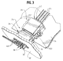
- Backplane connector assembly 26 and daughterboard connector assembly 28 are mateable in the direction of arrows "A" (Figs. 1 and 2) to a mated condition shown in Figure 3, wherein the fibers of cables 40 and 44 are functionally connected.
- adapter 36 includes a housing 46 which may be fabricated of molded plastic material.
- the housing defines a front mating end 46a and a rear terminating end 46b.
- the front mating end is open, as at 46c, and through which the ferrules (described hereinafter) of fiber optic connector modules 38 can project.
- Terminating end 46b is open, as at 46d, for receiving connector modules 38 in the direction of arrows "B".
- Housing 46 of adapter 36 has an outwardly projecting alignment rib 48 on each opposite side thereof and extending in the mating direction of the connector assembly, for purposes described hereinafter.
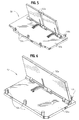
- FIG. 5 shows a shutter assembly, generally designated 50, for closing opening 46b of adapter 46
- Figure 6 shows a shutter assembly, generally designated 52, for closing mating opening 46c of the adapter.
- Shutter assembly 50 includes a pair of spring-loaded shutters 50a which close opening 46d on opposite sides of an interior partition 54 (Fig. 4).
- the shutter members are pivotally mounted on a plate 50b which includes a plurality of pegs 50c which are press-fit into holes 56 in adapter housing 46.
- shutter 52a of shutter assembly 52 is spring-loaded and is mounted on a plate 52b which has a plurality of pegs 52c which are press-fit into a plurality of holes 58 in adapter housing 46.
- Shutters 50a and 52a provide dust covers for the interior of adapter 36.
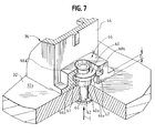
- a pair of T-nuts are floatingly mounted to adapter 36 and receive a pair of rivets 62 insertable in the direction of arrows "C" through a pair of mounting holes 64 in the backplane.
- the rivets have enlarged head portions 62a which will engage the surface of the backplane.
- Mounting holes 64 are spaced on opposite sides of opening 30.
- each T-nut 60 includes a shank portion 60a and an enlarged head 60b.
- a mounting flange, generally designed 66, is molded integrally with each opposite side of adapter housing 46.
- Each flange 66 includes an interior cavity 66a which receives head portion 60b of one of the T-nuts 60.
- a passage 66b extends through flange 66 toward backplane 32 in communication with cavity 66a for receiving shank portion 60a of the T-nut.
- head portion 60b are smaller than cavity 66a so that the head portion can float within the cavity
- the cross dimensions of shank portion 60a are less than the dimensions of passage 66b so that the shank portion can float within the passage
- the length of shank portion 60a is greater than the thickness of a wall portion 67 of flange 66 below the head portion (i.e., the thickness indicated by double-headed arrow "D" (Fig. 7). Therefore, when rivet 62 tightens the T-nut onto surface 32a of backplane 32, the adapter does not become tightened to the backplane and is allowed to float relative thereto.
- passage 66b has a restricted mouth, as at 66e, so that the T-nut can be snap-fit into flange 66 to mount the nut to adapter housing 46.
- rivet 62 equally could be a threaded fastener, such as a screw, for threadingly engaging the T-nut.
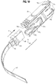
- FIGs 8-10 show one of the fiber optic connector modules 38 which are inserted into adapter 36 as described above.
- each module 38 includes a ferrule 68 terminated to one of the multi-fiber cables 40 with ends 40a (Fig. 8) of the fibers exposed at a mating face 68a of the ferrule.
- the ferrule includes a pair of alignment holes 68b opening into mating face 68a.
- the ferrule is captured by a manually manipulatable housing, generally designated 70, which includes a front portion 70a which actually captures the ferrule, and a rear portion defined by a pair of laterally spaced arms 70b that are graspable between an operator's fingers.
- Figure 10 shows that ferrule 68 has a peripheral flange 68c.
- the front portion 70a of housing 70 includes a pair of forward latch hooks 70c on two opposite sides of the housing and a pair of flexible latch arms 70d on the other two opposite sides of the housing.
- each latch arm 70d includes an inside chamfered latch hook 70e.
- Latch hooks 70c engage the front of flange 68c of the ferrule
- latch hooks 70e on latch arms 70d engage the rear edges of flange 68c to hold the ferrule encapsulated within front portion 70a of housing 70.
- manually graspable arms 70 include serrations 71 on the outsides thereof to facilitate manual grasping thereof.
- a latch block 70f projects outwardly from each arm for latching engagement within adapter 36.
- Each arm 70b also includes an interior channel 70g for guiding ferrule 68 into front portion 70a of the housing.
- FIG 10 shows that ferrule 68 is insertable into housing 70 of connector module 38 in the direction of arrow "E".
- the ferrule moves within channels 70g of arms 70b and through an open rear end 70h of front portion 70a of the housing.
- the ferrule becomes latched in a position projecting out of an open front end 70i (Fig. 9) of the housing and is locked in the position shown in Figure 8, with the ferrule projecting forwardly of the manually manipulatable housing.
- FIGs 11-13 show daughterboard connector assembly 28 to include a two-part housing defined by a front housing part, generally designated 72, and a rear housing part, generally designated 74.
- the rear housing part is insertable into the front housing part in the direction of arrow "F" (Fig. 11).
- Rear housing part 74 has a flexible latch arm 74a with a latch hook 74b which latches behind a front latch shoulder 72a (Fig. 13) when the two housing parts are initially assembled.
- Figure 13 also shows a second latch shoulder 72b which is located rearwardly of latch shoulder 72a, for purposes described hereinafter.
- Each housing part 72 and 74 may be a one-piece structure unitarily molded of dielectric material such as plastic or the like.
- a system for mounting front housing part 72 of daughterboard connector assembly 28 on daughterboard 34 with considerable precision.
- the daughterboard has a pre-placement hole 76 spaced between a pair of positioning holes 78 of as seen in Figure 11.
- a pair of rivets 80 are insertable through positioning holes 78.
- a pre-positioning peg 82 projects downwardly from a bottom surface 72d of front housing part 72 for insertion into pre-placement hole 76 with substantially zero insertion forces.
- hole 76 is larger than peg 82.
- a pair of positioning pegs 84 project downwardly from surface 70d for insertion into positioning holes 78 in daughterboard 34 by a press-fit to precisely fix the housing on the substrate.
- Peg 82 is solid, but pegs 84 are hollow for receiving rivets 80 therethrough to solidly lock the front housing part to the daughterboard.
- Pre-placement peg 82 is longer than positioning pegs 84 so that it is easy for an operator to locate and insert pre-placement peg 82 into pre-placement hole 76. The housing then can be easily pivoted about peg 82 until positioning pegs 84 are aligned with positioning holes 78.
- positioning pegs 84 are provided with crushable ribs 84a on the exterior thereof and which are crushed or deformed when pegs 84 are press-fit into holes 78.
- Bottom surface 72d of front housing part 72 is recessed, as at 86, around each positioning peg 84. This recessed area is provided for receiving any plastic material, such as crushable ribs 84a, which might be shaved off of positioning pegs 84 when they are press-fit into positioning holes 78. This ensures that bottom surface 72d of front housing part 72 is mounted flush on the flat top surface of daughterboard 34.
- front housing part 72 includes a pair of alignment flanges 88 at opposite sides of an open mating end 72e of the front housing part.
- Each flange has an outwardly chamfered or flared distal end 88a which is engageable by the front edges 90 (Fig. 1) of adapter 36 upon mating of the two connector assemblies.
- flared distal ends 88a allow for a degree of misalignment between the connector assemblies in an "X" direction generally perpendicular to mating direction "A" (Fig. 1) of the connectors, the "X" direction being generally parallel to daughterboard 34.
- Alignment flanges 88 have grooves or slots 88b on the insides thereof for receiving alignment ribs 48 (Fig. 1) on opposite sides of adapter housing 46. Slots 88b have flared mouths 88c which are engageable by the distal ends of alignment ribs 48 to allow for a degree of misalignment between the two connector assemblies in a "Y" direction generally perpendicular to mating direction "A” as well as generally perpendicular to the aforesaid "X" direction and daughterboard 44.
- alignment flanges 88 with the outwardly flared distal ends 88a thereof in combination with flared mouths 88c of slots 88b, are unique in utilizing a singular structure to allow for misalignment in two different "X" and "Y" directions.
- a bottom flange 92 projects forwardly of front housing part 72 flush with bottom surface 72d (Fig. 12) of the front housing part.
- the flange has a bottom hook portion 92a and a top chamfered portion 92b.
- the bottom hook portion overlaps an edge 94 of daughterboard 34.
- the top chamfered portion 92b is engageable by the front bottom edge of adapter housing 46 to prevent the bottom edge of the housing from "stubbing" the front edge of the daughterboard during mating of the connector assemblies.
- FIGs 14-19 show in greater detail one of the fiber optic connector modules 42 inserted into rear housing part 74 of daughterboard connector assembly 28.
- each module 42 includes a ferrule 96 for terminating multi-fiber cable 44, with a resilient boot 98 providing strain-relief for the cable.
- the ferrule includes a pair of through holes or passages 96a (Fig. 15) for receiving a pair of alignment pins 100 fixed to a pin keeper 102 which abuts against the rear of ferrule 96 so that the distal ends of alignment pins 100 project forwardly of a front mating face 96b of ferrule 96.
- a coil spring 104 is fixed to a rear end of pin keeper 102 as described hereinafter, and a spring pusher member 106 is fixed to the rear end of the coil spring.
- Both pin keeper 102 and pusher member 106 may be fabricated of molded plastic material.
- An integral, flexible latch arm 107 projects outwardly from the pusher member for latching the fiber optic connector module within rear housing part 74 of daughterboard connector assembly 28.
- Figure 16 shows that pin keeper 102 has a receptacle 102a at a rear end thereof for receiving a front end of coil spring 104, along with a locking flange 102b for locking with a coil at the front end of the spring.
- one of the locking flanges 102b are disposed at each opposite side of receptacle 102a of pin keeper 102.
- Figure 17 shows pusher member 106 to have a front receptacle 106a at a front end thereof for receiving a rear end of coil spring 104.
- a locking flange 106b is disposed at each opposite side of receptacle 106a for locking with a coil at the rear end of the coil spring.
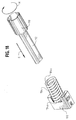
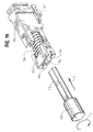
- Figures 18 and 19 show the procedure for assembling coil spring 104 between pin keeper 102 and pusher member 106 and locking the coil spring to those components.
- coil spring 104 is oval in cross-configuration.
- a tool 110 has a generally oval shaft 112 for insertion in the direction of arrow "G” into oval coil spring 104. The tool then is rotated in the direction of arrow "H” to effectively rotate the coil spring and cause the front open end coil 104a to lock behind flanges 102b (Fig. 16) of pin keeper 102.
- This subassembly then is positioned as shown in Figure 19 so that the opposite open end coil 104b (Fig. 18) is aligned with locking flanges 106b of pusher member 106.
- Shaft 112 of tool 110 then is inserted in the direction of arrow "I” (Fig. 19) into a rectangular hole 114 in pin keeper 102 and into coil spring 104, and the tool rotated in the direction of arrow "J".
- Alignment pins 100 then are fixed within slots 116 (Fig. 19) so that they extend from the pin keeper as seen in Figure 15.
- Boot 98 then is inserted into opening 114 of the pin keeper; ferrule 96 is positioned onto alignment pins 100; fiber optic cable 44 is inserted into and through the entire assembly in the direction of arrow "K” (Fig. 15); and the alignment pins and cable are epoxied within the ferrule so that an entire self-contained unit is formed as shown in Figure 14.
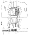
- Figures 20-22 show the mating procedure of backplane connector assembly 26 and daughterboard connector assembly 28 in the direction of arrows "A", after the backplane assembly is mounted to backplane or motherboard 32 and after the daughterboard connector assembly is mounted to daughterboard 34. These depictions also show that fiber optic cables 40 are engaged with yet another substrate or board 120.
- Figure 20 best shows that adapter 36 of backplane connector assembly 26 has a pair of actuator arms 122 spaced outwardly from opposite sides thereof. The distal ends of actuator arms 122 are formed with a latch hook 122a and a forwardly facing chamfer 122b.
- Backplane connector assembly 26 and daughterboard connector assembly 28 are mateable in a two-step process represented by Figures 21 and 22.
- hooks 122a of actuator arms 122 snap behind a pair of preliminary latch shoulders 124 (Figs. 1 and 20) of rear housing part 74 of daughterboard connector assembly 28.
- Latch hooks 74b on the ends of latch arms 74a at opposite sides of the rear housing part already have latched behind latch shoulders 72a (Fig. 14) of front housing part 72. This prevents any rearward movement of any part of daughterboard connector assembly 28 in response to the preliminary latching of backplane connector assembly 26 thereto.
Landscapes
- Physics & Mathematics (AREA)
- General Physics & Mathematics (AREA)
- Optics & Photonics (AREA)
- Mechanical Coupling Of Light Guides (AREA)
Abstract
Description
Claims (14)
- A fiber optic connector module (38), comprising:a ferrule (68) terminated to at least one optical fiber (40); anda manually manipulatable housing (70) within which the ferrule is mounted, the housing including a front portion (70a) encapsulating the ferrule (68) and a rear portion (70b) extending rearwardly of the front portion for manual grasping by an operator, the front portion having an open front end (70i) through which a mating end (68a) of the ferrule projects and an open rear end (70h) through which the optical fiber extends.
- The fiber optic connector module of claim 1 wherein said rear portion of the housing (70) comprises a pair of laterally spaced arms (70b) graspable between an operator's fingers.
- The fiber optic connector module of claim 2 wherein the outsides of said arms (70b) have serrations (70e) to facilitate manual grasping thereof.
- The fiber optic connector module of claim 2 wherein the insides of said arms (70b) have guide channels (70g) for guiding insertion of the ferrule (68) into the open rear end (70h) of said front portion (70a).
- The fiber optic connector module of claim 1, including latch means (70f) on the outside of said housing (70) for latching the module (38) in a complementary receptacle.
- The fiber optic connector module of claim 1 ,including guide means (70g) on said rear portion (70b) of the housing (70) for guiding insertion of the ferrule (68) into the open rear end (70h) of said front portion (70a).
- The fiber optic connector module of claim 1, including latch means (70c,70d) on said front portion (70a) of the housing for holding the ferrule (68) encapsulated therein.
- The fiber optic connector module of claim 7 wherein said latch means comprise flexible latch arms (70c,70d) engageable with opposite sides of a flange (68c) of the ferrule (68).
- The fiber optic connector module of claim 1 wherein said housing (70) is a one-piece structure unitarily molded of plastic material.
- A fiber optic connector module (38), comprising:a ferrule (68) terminated to at least one optical fiber (40); anda manually manipulatable, one-piece housing (70) within which the ferrule (68) is mounted, the housing includes a front portion (70a) encapsulating the ferrule, latch means (70c,70d) on said front portion for holding the ferrule encapsulated therein, a rear portion formed by a pair of laterally spaced arms (70b) graspable between an operator's fingers and extending rearwardly of said front portion (70a), the front portion having an open front end (70i) through which a mating end (68a) of the ferrule (68) projects and an open rear end (70h) through which the optical fiber extends.
- The fiber optic connector module of claim 10 wherein the outsides of said arms (70b) have serrations (70e) to facilitate manual grasping thereof.
- The fiber optic connector module of claim 10 wherein the insides of said arms (70b) have guide channels (70g) for guiding insertion of the ferrule (68) into the open rear end (70h) of said front portion (70a).
- The fiber optic connector module of claim 10, including latch means (70f) on the outsides of said arms (70b) for latching the module in a complementary receptacle.
- The fiber optic connector module of claim 10 wherein said latch means comprise flexible latch arms (70c,70d) engageable with opposite sides of a flange (68c) of the ferrule (68).
Applications Claiming Priority (2)
| Application Number | Priority Date | Filing Date | Title |
|---|---|---|---|
| US09/456,197 US6361218B1 (en) | 1999-12-07 | 1999-12-07 | Fiber optic connector module |
| US456197 | 1999-12-07 |
Publications (2)
| Publication Number | Publication Date |
|---|---|
| EP1107032A1 true EP1107032A1 (en) | 2001-06-13 |
| EP1107032B1 EP1107032B1 (en) | 2008-02-20 |
Family
ID=23811855
Family Applications (1)
| Application Number | Title | Priority Date | Filing Date |
|---|---|---|---|
| EP00126669A Expired - Lifetime EP1107032B1 (en) | 1999-12-07 | 2000-12-05 | Fiber optic connector module |
Country Status (8)
| Country | Link |
|---|---|
| US (1) | US6361218B1 (en) |
| EP (1) | EP1107032B1 (en) |
| JP (1) | JP3424172B2 (en) |
| KR (1) | KR100388762B1 (en) |
| CN (1) | CN1183395C (en) |
| DE (1) | DE60038089T2 (en) |
| SG (1) | SG97979A1 (en) |
| TW (1) | TW468794U (en) |
Cited By (5)
| Publication number | Priority date | Publication date | Assignee | Title |
|---|---|---|---|---|
| NL1024108C2 (en) * | 2003-08-14 | 2005-02-15 | Framatome Connectors Int | Optical board connector assembly. |
| WO2004059512A3 (en) * | 2002-12-20 | 2005-03-31 | Teradyne Inc | Optical fiber ferrule assembly and methods of construction |
| WO2006086153A1 (en) * | 2005-02-08 | 2006-08-17 | Molex Incorporated | Hermaphroditic fibre optical connector system |
| EP2444827A1 (en) * | 2010-10-22 | 2012-04-25 | Radiall | Optical contact, multi-contact connector and method for connecting two optical contacts |
| WO2017102517A1 (en) * | 2015-12-14 | 2017-06-22 | Huber+Suhner Ag | Optical connector assembly |
Families Citing this family (44)
| Publication number | Priority date | Publication date | Assignee | Title |
|---|---|---|---|---|
| US5883995A (en) | 1997-05-20 | 1999-03-16 | Adc Telecommunications, Inc. | Fiber connector and adapter |
| US6715931B1 (en) * | 1999-12-07 | 2004-04-06 | Wenzong Chen | Self-contained fiber optic connector module |
| US7422376B2 (en) * | 1999-12-07 | 2008-09-09 | Molex Incorporated | Self-contained fiber optic connector module |
| JP3529339B2 (en) * | 2000-09-14 | 2004-05-24 | 日本電気通信システム株式会社 | Optical adapter mounting structure |
| WO2002048752A2 (en) * | 2000-12-13 | 2002-06-20 | Teraconnect, Inc. | An optical waveguide assembly for interfacing a two-dimensional optoelectronic array to fiber bundles |
| USD476625S1 (en) | 2001-03-14 | 2003-07-01 | Honda Tsushin Kogyo Co. Ltd. | Light connector with a shutter |
| USD476626S1 (en) | 2001-03-14 | 2003-07-01 | Honda Tsushin Kogyo Co. Ltd. | Light connector with a shutter (double vertical type) |
| USD476624S1 (en) | 2001-03-14 | 2003-07-01 | Honda Tsushin Kogyo Co. Ltd. | Light connector with a shutter (double horizontal type) |
| US6520687B2 (en) * | 2001-04-06 | 2003-02-18 | Shen-Chia Wong | Optical fiber signal connector |
| DE10124028B4 (en) * | 2001-05-16 | 2010-02-18 | 3M Espe Ag | Self-adhesive dental materials |
| US6533463B2 (en) * | 2001-07-31 | 2003-03-18 | Pluris, Inc. | Adjustable and modular backplane assembly for providing a fiber-optics communication backplane |
| US7073953B2 (en) * | 2001-08-31 | 2006-07-11 | Amphenol Corporation | Modular fiber optic connection system |
| US6592266B1 (en) * | 2001-10-04 | 2003-07-15 | Advanced Fibre Communications, Inc. | Fiber optic cable connector clip |
| US6688780B2 (en) | 2002-02-07 | 2004-02-10 | Amphenol Corporation | Cantilevered shutter for optical adapter |
| US6839935B2 (en) * | 2002-05-29 | 2005-01-11 | Teradyne, Inc. | Methods and apparatus for cleaning optical connectors |
| US6762941B2 (en) | 2002-07-15 | 2004-07-13 | Teradyne, Inc. | Techniques for connecting a set of connecting elements using an improved latching apparatus |
| US6832858B2 (en) * | 2002-09-13 | 2004-12-21 | Teradyne, Inc. | Techniques for forming fiber optic connections in a modularized manner |
| US6811322B2 (en) * | 2002-10-24 | 2004-11-02 | Molex Incorporated | Fiber optic connector module |
| US7042562B2 (en) * | 2002-12-26 | 2006-05-09 | Amphenol Corp. | Systems and methods for inspecting an optical interface |
| US7144163B2 (en) * | 2003-01-27 | 2006-12-05 | Fujikura Ltd. | Optical connector with shutter, shutter unit, and inner piece |
| US6986607B2 (en) * | 2003-09-26 | 2006-01-17 | Roth Richard F | Protective covers for fiber optic connector to modular protective covers for fiber optic connector assembly |
| JP3815739B2 (en) * | 2003-09-30 | 2006-08-30 | 日本航空電子工業株式会社 | Receptacle type split optical connector |
| US7011456B2 (en) * | 2003-11-12 | 2006-03-14 | Johnson Yang | Connector for an optical transmitting and receiving device |
| US7373031B2 (en) * | 2004-09-30 | 2008-05-13 | Intel Corporation | Apparatus for an electro-optical device connection |
| US7835006B2 (en) * | 2004-11-05 | 2010-11-16 | Nomadics, Inc. | Optical fiber sensors using grating-assisted surface plasmon-coupled emission (GASPCE) |
| JP4155584B2 (en) * | 2004-12-28 | 2008-09-24 | 日本航空電子工業株式会社 | Optical connector |
| US7364366B2 (en) * | 2005-02-02 | 2008-04-29 | Viasystems Group, Inc. | Circuit board assembly having a guide insert |
| JP4981382B2 (en) * | 2006-08-18 | 2012-07-18 | 古河電気工業株式会社 | Optical connector |
| US8083547B2 (en) * | 2008-10-01 | 2011-12-27 | Amphenol Corporation | High density pluggable electrical and optical connector |
| CN102324655B (en) * | 2011-06-09 | 2012-12-12 | 上海航天科工电器研究院有限公司 | A floating power connector |
| CN102854572B (en) * | 2011-06-30 | 2017-05-24 | 成都康宁光缆有限公司 | Optical fiber connector, manufacturing method thereof and cable assembly |
| US8540435B2 (en) * | 2011-07-22 | 2013-09-24 | Corning Cable Systems Llc | Ferrule retainers having access window(s) for accessing and/or referencing a fiber optic ferrule, and related fiber optic connector assemblies, connectors, and referencing methods |
| US9354399B2 (en) * | 2012-08-07 | 2016-05-31 | Molex, Llc | Optical fiber connector assembly |
| US9857538B2 (en) | 2013-03-15 | 2018-01-02 | Us Conec, Ltd. | Alignment adapter and alignment design for a connector therefor |
| CN105745564B (en) | 2013-09-30 | 2017-10-24 | 慧与发展有限责任合伙企业 | Optics is blind to match somebody with somebody formula connector and adapter |
| US10222557B2 (en) | 2014-09-29 | 2019-03-05 | Us Conec, Ltd. | Spring push with integral trigger |
| US9874702B2 (en) * | 2014-10-29 | 2018-01-23 | Hewlett Packard Enterprise Development Lp | Optical connector assembly apparatus |
| TWI608261B (en) * | 2016-11-29 | 2017-12-11 | 普泰光電股份有限公司 | Optical fiber adapter with shutter member |
| CN106646776B (en) * | 2016-11-30 | 2018-11-13 | 中航光电科技股份有限公司 | A kind of pin connector and its housing unit |
| WO2020176493A1 (en) * | 2019-02-25 | 2020-09-03 | Juggernaut Defense, Llc | Systems and methods for a cable clip |
| US11506847B2 (en) * | 2020-07-23 | 2022-11-22 | Te Connectivity Solutions Gmbh | Modularized insert assembly for backplane connector |
| US11892685B2 (en) * | 2020-09-23 | 2024-02-06 | Senko Advanced Components, Inc. | Fiber optic adapter |
| US11199669B1 (en) * | 2020-09-24 | 2021-12-14 | Hewlett Packard Enterprise Development Lp | Modular faceplate optical sub-assembly |
| EP4254032B1 (en) * | 2020-12-22 | 2025-08-27 | Huawei Technologies Co., Ltd. | Fiber-optic interface, optical module and communication device |
Citations (1)
| Publication number | Priority date | Publication date | Assignee | Title |
|---|---|---|---|---|
| WO1988005925A1 (en) * | 1987-02-03 | 1988-08-11 | American Telephone & Telegraph Company | Duplex optical fiber connector |
Family Cites Families (11)
| Publication number | Priority date | Publication date | Assignee | Title |
|---|---|---|---|---|
| US4611887A (en) * | 1983-02-24 | 1986-09-16 | Amp Incorporated | Fiber optic connector assembly and wall outlet thereof |
| EP0307518B1 (en) * | 1984-06-08 | 1993-07-28 | The Whitaker Corporation | High precision fiber optic connectors |
| JP2674790B2 (en) | 1988-07-29 | 1997-11-12 | 日本電気株式会社 | Optical connector locking structure |
| JPH0282206A (en) * | 1988-09-19 | 1990-03-22 | Mitsubishi Rayon Co Ltd | Optical fiber cord with connector |
| US5121454A (en) | 1989-11-24 | 1992-06-09 | Nippon Telegraph And Telephone Corporation | Optical connector |
| GB9307488D0 (en) | 1993-04-08 | 1993-06-02 | Amp Holland | Optical fibre connector latching mechanism |
| JPH08160255A (en) * | 1994-12-06 | 1996-06-21 | Nikko Kapura:Kk | Connector for polarization maintaining optical fiber |
| DE19547525C1 (en) * | 1995-12-08 | 1997-02-20 | Siemens Ag | Releasable plug-connector esp. single-piece expandable plug for coupling of e.g. optical waveguides |
| JPH1073744A (en) * | 1996-09-02 | 1998-03-17 | Sumitomo Electric Ind Ltd | Optical connector |
| JP4036912B2 (en) * | 1996-12-05 | 2008-01-23 | 株式会社フジクラ | Optical connector |
| JP3447196B2 (en) * | 1997-04-30 | 2003-09-16 | 株式会社フジクラ | Optical connector detachment mechanism and optical connector connection tool |
-
1999
- 1999-12-07 US US09/456,197 patent/US6361218B1/en not_active Expired - Lifetime
-
2000
- 2000-11-23 SG SG200006775A patent/SG97979A1/en unknown
- 2000-12-05 EP EP00126669A patent/EP1107032B1/en not_active Expired - Lifetime
- 2000-12-05 DE DE60038089T patent/DE60038089T2/en not_active Expired - Fee Related
- 2000-12-05 JP JP2000403877A patent/JP3424172B2/en not_active Expired - Fee Related
- 2000-12-06 CN CNB001350889A patent/CN1183395C/en not_active Expired - Lifetime
- 2000-12-06 TW TW089221193U patent/TW468794U/en not_active IP Right Cessation
- 2000-12-06 KR KR10-2000-0073564A patent/KR100388762B1/en not_active Expired - Fee Related
Patent Citations (1)
| Publication number | Priority date | Publication date | Assignee | Title |
|---|---|---|---|---|
| WO1988005925A1 (en) * | 1987-02-03 | 1988-08-11 | American Telephone & Telegraph Company | Duplex optical fiber connector |
Cited By (10)
| Publication number | Priority date | Publication date | Assignee | Title |
|---|---|---|---|---|
| WO2004059512A3 (en) * | 2002-12-20 | 2005-03-31 | Teradyne Inc | Optical fiber ferrule assembly and methods of construction |
| US7204016B2 (en) | 2002-12-20 | 2007-04-17 | Amphenol Corporation | Ferrule assembly and methods therefor |
| US7845859B2 (en) | 2002-12-20 | 2010-12-07 | Amphenol Corporation | Ferrule assembly and methods thereof |
| NL1024108C2 (en) * | 2003-08-14 | 2005-02-15 | Framatome Connectors Int | Optical board connector assembly. |
| WO2005017591A1 (en) * | 2003-08-14 | 2005-02-24 | Fci | Optical board connector assembly |
| WO2006086153A1 (en) * | 2005-02-08 | 2006-08-17 | Molex Incorporated | Hermaphroditic fibre optical connector system |
| EP2444827A1 (en) * | 2010-10-22 | 2012-04-25 | Radiall | Optical contact, multi-contact connector and method for connecting two optical contacts |
| FR2966609A1 (en) * | 2010-10-22 | 2012-04-27 | Radiall Sa | OPTICAL CONTACT, MULTICONTACT CONNECTOR AND METHOD FOR CONNECTING TWO OPTICAL CONTACTS |
| US8961033B2 (en) | 2010-10-22 | 2015-02-24 | Radiall | Optical contact and multicontact connector |
| WO2017102517A1 (en) * | 2015-12-14 | 2017-06-22 | Huber+Suhner Ag | Optical connector assembly |
Also Published As
| Publication number | Publication date |
|---|---|
| JP2001350058A (en) | 2001-12-21 |
| TW468794U (en) | 2001-12-11 |
| KR20010070266A (en) | 2001-07-25 |
| DE60038089T2 (en) | 2009-03-05 |
| EP1107032B1 (en) | 2008-02-20 |
| JP3424172B2 (en) | 2003-07-07 |
| DE60038089D1 (en) | 2008-04-03 |
| CN1183395C (en) | 2005-01-05 |
| SG97979A1 (en) | 2003-08-20 |
| CN1299069A (en) | 2001-06-13 |
| US6361218B1 (en) | 2002-03-26 |
| KR100388762B1 (en) | 2003-06-25 |
Similar Documents
| Publication | Publication Date | Title |
|---|---|---|
| EP1107032B1 (en) | Fiber optic connector module | |
| EP1107031B1 (en) | Alignment system for mating connectors | |
| EP1107368B1 (en) | Mounting system for a connector assembly to a substrate | |
| EP1107367B1 (en) | Connector assembly floating mount | |
| US6715931B1 (en) | Self-contained fiber optic connector module | |
| US7422376B2 (en) | Self-contained fiber optic connector module | |
| EP1139504B1 (en) | Floating connector assembly | |
| EP1014126A2 (en) | Connector assembly | |
| US6981803B2 (en) | Fiber optic connector module having rear extender |
Legal Events
| Date | Code | Title | Description |
|---|---|---|---|
| PUAI | Public reference made under article 153(3) epc to a published international application that has entered the european phase |
Free format text: ORIGINAL CODE: 0009012 |
|
| AK | Designated contracting states |
Kind code of ref document: A1 Designated state(s): DE FR GB IT |
|
| AX | Request for extension of the european patent |
Free format text: AL;LT;LV;MK;RO;SI |
|
| 17P | Request for examination filed |
Effective date: 20011130 |
|
| AKX | Designation fees paid |
Free format text: DE FR GB IT |
|
| 17Q | First examination report despatched |
Effective date: 20050314 |
|
| GRAP | Despatch of communication of intention to grant a patent |
Free format text: ORIGINAL CODE: EPIDOSNIGR1 |
|
| GRAS | Grant fee paid |
Free format text: ORIGINAL CODE: EPIDOSNIGR3 |
|
| GRAA | (expected) grant |
Free format text: ORIGINAL CODE: 0009210 |
|
| AK | Designated contracting states |
Kind code of ref document: B1 Designated state(s): DE FR GB IT |
|
| REG | Reference to a national code |
Ref country code: GB Ref legal event code: FG4D |
|
| RIN1 | Information on inventor provided before grant (corrected) |
Inventor name: GROIS, IGOR Inventor name: CHEN, WENZONG Inventor name: MATASEK, JEFFREY A. |
|
| REF | Corresponds to: |
Ref document number: 60038089 Country of ref document: DE Date of ref document: 20080403 Kind code of ref document: P |
|
| ET | Fr: translation filed | ||
| PLBE | No opposition filed within time limit |
Free format text: ORIGINAL CODE: 0009261 |
|
| STAA | Information on the status of an ep patent application or granted ep patent |
Free format text: STATUS: NO OPPOSITION FILED WITHIN TIME LIMIT |
|
| 26N | No opposition filed |
Effective date: 20081121 |
|
| PGFP | Annual fee paid to national office [announced via postgrant information from national office to epo] |
Ref country code: IT Payment date: 20081222 Year of fee payment: 9 |
|
| PGFP | Annual fee paid to national office [announced via postgrant information from national office to epo] |
Ref country code: DE Payment date: 20090202 Year of fee payment: 9 |
|
| GBPC | Gb: european patent ceased through non-payment of renewal fee |
Effective date: 20081205 |
|
| REG | Reference to a national code |
Ref country code: FR Ref legal event code: ST Effective date: 20090831 |
|
| PG25 | Lapsed in a contracting state [announced via postgrant information from national office to epo] |
Ref country code: GB Free format text: LAPSE BECAUSE OF NON-PAYMENT OF DUE FEES Effective date: 20081205 |
|
| PG25 | Lapsed in a contracting state [announced via postgrant information from national office to epo] |
Ref country code: FR Free format text: LAPSE BECAUSE OF NON-PAYMENT OF DUE FEES Effective date: 20081231 |
|
| PG25 | Lapsed in a contracting state [announced via postgrant information from national office to epo] |
Ref country code: DE Free format text: LAPSE BECAUSE OF NON-PAYMENT OF DUE FEES Effective date: 20100701 |
|
| PG25 | Lapsed in a contracting state [announced via postgrant information from national office to epo] |
Ref country code: IT Free format text: LAPSE BECAUSE OF NON-PAYMENT OF DUE FEES Effective date: 20091205 |