EP1106919B1 - Methods and apparatus for decreasing combustor emissions - Google Patents
Methods and apparatus for decreasing combustor emissions Download PDFInfo
- Publication number
- EP1106919B1 EP1106919B1 EP00310985A EP00310985A EP1106919B1 EP 1106919 B1 EP1106919 B1 EP 1106919B1 EP 00310985 A EP00310985 A EP 00310985A EP 00310985 A EP00310985 A EP 00310985A EP 1106919 B1 EP1106919 B1 EP 1106919B1
- Authority
- EP
- European Patent Office
- Prior art keywords
- splitter
- diameter
- pilot
- downstream
- extension
- Prior art date
- Legal status (The legal status is an assumption and is not a legal conclusion. Google has not performed a legal analysis and makes no representation as to the accuracy of the status listed.)
- Expired - Lifetime
Links
Images

Classifications
-
- F—MECHANICAL ENGINEERING; LIGHTING; HEATING; WEAPONS; BLASTING
- F23—COMBUSTION APPARATUS; COMBUSTION PROCESSES
- F23D—BURNERS
- F23D23/00—Assemblies of two or more burners
-
- F—MECHANICAL ENGINEERING; LIGHTING; HEATING; WEAPONS; BLASTING
- F23—COMBUSTION APPARATUS; COMBUSTION PROCESSES
- F23D—BURNERS
- F23D11/00—Burners using a direct spraying action of liquid droplets or vaporised liquid into the combustion space
- F23D11/10—Burners using a direct spraying action of liquid droplets or vaporised liquid into the combustion space the spraying being induced by a gaseous medium, e.g. water vapour
- F23D11/106—Burners using a direct spraying action of liquid droplets or vaporised liquid into the combustion space the spraying being induced by a gaseous medium, e.g. water vapour medium and fuel meeting at the burner outlet
- F23D11/107—Burners using a direct spraying action of liquid droplets or vaporised liquid into the combustion space the spraying being induced by a gaseous medium, e.g. water vapour medium and fuel meeting at the burner outlet at least one of both being subjected to a swirling motion
-
- F—MECHANICAL ENGINEERING; LIGHTING; HEATING; WEAPONS; BLASTING
- F23—COMBUSTION APPARATUS; COMBUSTION PROCESSES
- F23R—GENERATING COMBUSTION PRODUCTS OF HIGH PRESSURE OR HIGH VELOCITY, e.g. GAS-TURBINE COMBUSTION CHAMBERS
- F23R3/00—Continuous combustion chambers using liquid or gaseous fuel
- F23R3/28—Continuous combustion chambers using liquid or gaseous fuel characterised by the fuel supply
- F23R3/34—Feeding into different combustion zones
- F23R3/343—Pilot flames, i.e. fuel nozzles or injectors using only a very small proportion of the total fuel to insure continuous combustion
Definitions
- This invention relates to combustors, and more particularly, to gas turbine combustors.
- these emissions fall into two classes: those formed because of high flame temperatures (NOx), and those formed because of low flame temperatures which do not allow the fuel-air reaction to proceed to completion (HC & CO).
- NOx high flame temperatures
- HC & CO low flame temperatures which do not allow the fuel-air reaction to proceed to completion
- Hot spots are produced where the mixture of fuel and air is near a specific ratio where all fuel and air react (i.e. no unburned fuel or air is present in the products). This mixture is called stoichiometric. Cold spots can occur if either excess air is present in the products (called lean combustion), or if excess fuel is present in the products (called rich combustion).
- Modern gas turbine combustors consist of between 10 and 30 mixers, which mix high velocity air with a fine fuel spray. These mixers usually consist of a single fuel injection source located at the center of a device designed to swirl the incoming air to enhance flame stabilization and mixing. Both the fuel injector and mixer are located on the combustor dome. In general, the fuel to air ratio in the mixer is rich. Since the overall combustor fuel-air ratio of gas turbine combustors is lean, additional air is added through discrete dilution holes prior to exiting the combustor. Poor mixing and hot spots can occur both at the dome, where the injected fuel must vaporize and mix prior to burning, and in the vicinity of the dilution holes, where air is added to the rich dome mixture.
- rich dome combustors are very stable devices with wide flammability limits and can produce low HC and CO emissions, and acceptable NOx emissions.
- rich dome combustors a fundamental limitation on rich dome combustors exists, since the rich dome mixture must pass through stoichiometric or maximum NOx producing regions prior to exiting the combustor. This is particularly important as the operating pressure ratio (OPR) of modern gas turbines increases for improved cycle efficiencies and compactness, the combustor inlet temperatures and pressures increase the rate of NOx production dramatically. As emission standards become more stringent and OPR's increase, it appears unlikely that traditional rich dome combustors will be able to meet the challenge.
- OPR operating pressure ratio
- Lean dome combustors have the potential to solve some of these problems.
- One such current state-of-the-art design of lean dome combustor is referred to as a dual annular combustor (DAC) because it includes two radially stacked mixers on each fuel nozzle which appears as two annular rings when viewed from the front of the combustor.
- the additional row of mixers allows the design to be tuned for operation at different conditions.
- the outer mixer is fueled, which is designed to operate efficiently at idle conditions.
- both mixers are fueled with the majority of fuel and air supplied to the inner annulus, which is designed to operate most efficiently and with few emissions at higher powers.
- Such a design is a compromise between low NOx and CO/HC.
- EP 0 924 459 discloses a venturiless swirl cup for a gas turbine engine.
- the present invention is directed to a method for reducing an amount of carbon monoxide and hydrocarbon emissions and smoke from a gas turbine combustor according to claim 1, as well as to the combination of a baseline air blast splitter and an extension according to claim 3, and to a gas turbine combustor according to claim 7.
- Their depending claims are preferred embodiments of the invention
- a combustor operates with high combustion efficiency and low carbon monoxide, hydrocarbon, and smoke emissions.
- the combustor of the invention includes a fuel injector for injecting fuel into the combustor, a baseline air blast pilot splitter including a downstream side which converges towards a center body axis of symmetry, and a splitter extension.
- the splitter extension includes a converging upstream portion attached to the pilot splitter, a diverging downstream portion, and an intermediate portion extending between the upstream portion and the downstream portion. .
- the splitter extension increases an effective pilot flow swirl number for an inner and an outer vane angle.
- the increased effective swirl number results in a stronger on-axis recirculation zone.
- Recirculating gas provides oxygen for completing combustion in the fuel-rich pilot cup, creates intense mixing and high combustion rates, and burns off soot produced in the flame.
- the splitter extension enables a swirl stabilized flame with lower vane angles.
- the splitter extension also decreases the velocity of pilot fuel being injected into the combustor and the velocity of the pilot inner airflow stream. The lower velocities improve fuel and air mixing, and increase the fuel residence time in the flame. Fuel entrainment and carryover in the pilot outer airflow stream are also decreased by the splitter extension.
- the splitter extension physically delays the mixing of the pilot inner and outer airflows causing such a mixing to be less intense due to the lower velocities of the pilot airflows at the exit of the splitter extension.
- a combustor is provided which operates with a high combustion efficiency while maintaining low carbon monoxide, hydrocarbon, and smoke emissions.
- Figure 1 is a schematic illustration of a gas turbine engine 10 including a low pressure compressor 12, a high pressure compressor 14, and a combustor 16.
- Engine 10 also includes a high pressure turbine 18, a low pressure turbine 20, and a power turbine 22.
- Airflow from combustor 16 drives turbines 18, 20, and 22.
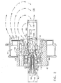
- FIG. 2 is a cross-sectional view of combustor 16 (shown in Figure 1) for a gas turbine engine (not shown).
- the gas turbine engine is a GE90 available from General Electric Company, Evendale, Ohio.
- the gas turbine engine is a F110 available from General Electric Company, Evendale, Ohio.
- Combustor 16 includes a center body 42, a main swirler 43, a pilot outer swirler 44, a pilot inner swirler 46, and a pilot fuel injector 48.
- Center body 42 has an axis of symmetry 60, and is generally cylindrical-shaped with an annular cross-sectional profile (not shown).
- An inner flame (not shown), sometimes referred to as a pilot is a spray diffusion flame fueled entirely from gas turbine start conditions.
- additional fuel is injected into combustor 16 through fuel injectors (not shown) disposed within center body 42.
- Pilot fuel injector 48 includes an axis of symmetry 62 and is positioned within center body 42 such that fuel injector axis of symmetry 62 is substantially co-axial with center body axis of symmetry 60.
- Fuel injector 48 injects fuel to the pilot and includes an intake side 64, a discharge side 66, and a body 68 extending between intake side 64 and discharge side 66.
- Discharge side 66 includes a convergent discharge nozzle 70 which directs a fuel-flow 72 outward from fuel injector 48 substantially parallel to center body axis of symmetry 60.
- Pilot inner swirler 46 is annular and is circumferentially disposed around pilot fuel injector 48. Pilot inner swirler 46 includes an intake side 80 and an outlet side 82. An inner pilot airflow stream 84 enters pilot inner swirler intake side 80 and exits outlet side 82.
- a baseline air blast pilot splitter 90 is positioned downstream from pilot inner swirler 46.
- Baseline air blast pilot splitter 90 includes an upstream side 92, and a downstream side 94.
- Upstream side 92 includes a leading edge 96 and has a diameter 98 which is constant from leading edge 96 to downstream side 94.
- Upstream side 92 includes an inner surface 99 positioned substantially parallel and adjacent pilot inner swirler 46.
- Baseline air blast pilot splitter downstream side 94 extends from upstream side 92 to a trailing edge 100 of baseline air blast pilot splitter 90. Trailing edge 100 has a diameter 102 less than upstream side diameter 98. Downstream side 94 is convergent towards pilot fuel injector 48 at an angle 104 with respect to center body axis of symmetry 60.
- Pilot outer swirler 44 extends substantially perpendicularly from baseline air blast pilot splitter 90 and attaches to a contoured wall 110. Contoured wall 110 is attached to center body 42. Pilot outer swirler 44 is annular and is circumferentially disposed around baseline air blast pilot splitter 90. Pilot outer swirler 44 has an intake side 112 and an outlet side 114. An outer pilot airflow stream 116 enters pilot outer swirler intake side 112 and is directed at an angle 118.
- a splitter extension 120 is positioned downstream from baseline air blast pilot splitter 90.
- Splitter extension 120 includes an upstream portion 122, a downstream portion 124, and an intermediate portion 126 extending between upstream portion 122 and downstream portion 124.
- Upstream portion 122 has a first diameter 130, an inner surface 132, and an outer surface 134.
- Inner surface 132 of splitter extension upstream portion 122 is convergent and is attached to downstream side 94 of baseline air blast pilot splitter 90.
- Intermediate portion 126 extends from upstream portion 122 and converges towards center body axis of symmetry 60.
- Intermediate portion 126 includes a second diameter 140 which is less than upstream portion first diameter 130, an inner surface 142, and an outer surface 144.
- Downstream portion 124 extends from intermediate portion 126 and includes an inner surface 150, an outer surface 152, and a third diameter 154. Downstream portion 124 is divergent from center body axis of symmetry 60 and accordingly third diameter 154 is larger than intermediate portion second diameter 140.
- Splitter extension downstream portion 124 diverges towards contoured wall 110.
- Contoured wall 110 includes an apex 156 positioned between a convergent section 158 of contoured wall 110 and a divergent section 160 of contoured wall 110.
- Splitter extension 120 includes a length 168 which extends from splitter extension upstream portion 122 to splitter extension downstream portion 124.
- Contoured wall 110 extends to main swirler 43.
- Main swirler 43 is positioned circumferentially around contoured wall 110 and directs swirling airflow 170 into a combustor cavity 178.
- inner pilot airflow stream 84 enters pilot inner swirler intake side 80 and is accelerated outward from inner swirler outlet side 82.
- Inner pilot airflow stream 84 flows substantially parallel to center body axis of symmetry 60 and strikes baseline air blast splitter 90. Pilot splitter 90 directs inner airflow 84 in a swirling motion towards fuel-flow 72 at angle 104. Inner airflow 84 impinges on fuel-flow 72 to mix and atomize fuel-flow 72 without collapsing a spray pattern (not shown) exiting pilot fuel injector 48.
- outer pilot airflow stream 116 is accelerated through pilot outer swirler 44.
- Outer airflow 116 exits outer swirler 44 flowing substantially parallel to center body axis of symmetry 60.
- Outer airflow 116 continues substantially parallel to center body axis of symmetry 60 and strikes contoured wall 110.
- Contoured wall 110 directs outer airflow 116 at angle 118 towards center body axis of symmetry in a swirling motion.
- Outer airflow 116 continues flowing towards center body axis of symmetry 60 and strikes splitter extension upstream outer surface 134.
- Splitter extension upstream outer surface 134 directs airflow 116 towards splitter extension intermediate outer surface 144 where airflow 116 is redirected towards contoured wall divergent section 160.
- Outer airflow 116 flows over splitter extension length 168 and continues flowing substantially parallel to contoured wall 110 until impacted upon by airflow 170 exiting main swirler 43.
- Inner pilot airflow stream 84 impinges on fuel-flow 72 to create a fuel and air mixture which flows through splitter extension 120.
- Splitter extension 120 decelerates the velocity of the mixture and thus increases the amount of residence time for the mixture within center body 42. The increased residence time permits greater evaporation and improves the mixing of fuel-flow 72 and inner pilot airflow stream 84. The lower velocity also permits the mixture to spend more time inside a pilot flame (not shown) to provide a more thorough burning of the mixture.
- Splitter extension 120 increases a pilot swirl number and brings the flame inside center body 42, thus, substantially improving flame stability and decreasing carbon monoxide, hydrocarbon, and smoke emissions.
- Splitter extension length 168 permits splitter extension 120 to isolate outer pilot airflow stream 116 from inner pilot airflow stream 84 and delays any mixing between streams 84 and 116.
- Splitter extension length 168 also permits individual control of inner pilot airflow stream 84 and outer pilot airflow stream 116 which results in less fuel entrainment or carryover by outer pilot airflow stream 116.
- Individually controlling inner pilot airflow stream 84 and outer pilot airflow stream 116 permits the velocity of outer pilot airflow stream 116 to be decreased. Lowering the axial velocity of outer pilot airflow stream 116 creates a lower velocity differential between inner pilot airflow stream 84 and outer pilot airflow stream 116. The lower velocity increases the residence time and decreases the fuel entrainment and quenching by outer pilot airflow stream 116.
- combustor 16 operates with a high efficiency and with low carbon monoxide and hydrocarbon emissions.
- the increase in the pilot swirl number caused by splitter extension 120 results in a strong axial recirculation zone 180 which, in combination with the decreased velocity of the pilot fuel/air mixture, creates a strong suck back (not shown) within center body 42 which causes any unburned combustion products (not shown) to be recirculated in the pilot flame.
- a strong suck back (not shown) within center body 42 which causes any unburned combustion products (not shown) to be recirculated in the pilot flame.
- combustion efficiency is substantially improved.
- the recirculating combustion gas brings oxygen from main air stream 170 into the pilot flame.
- soot (not shown) produced in the pilot flame is burned off rather than emitted.
- the above-described combustor is cost-effective and highly reliable.
- the combustor includes a splitter extension including an upstream portion, a downstream portion, and an intermediate portion extending between the upstream portion and the downstream portion.
- the upstream portion is divergent and extends to a convergent intermediate portion.
- the convergent intermediate portion extends to a divergent downstream portion.
- a combustor is provided which operates with little fuel entrainment and an increased residence time for a fuel/air mixture within a center body portion of the combustor.
- a combustor is provided which operates at a high combustion efficiency and with low carbon monoxide, hydrocarbon, and low smoke emissions.
Description
- This invention relates to combustors, and more particularly, to gas turbine combustors.
- Air pollution concerns worldwide have led to stricter emissions standards both domestically and internationally. Aircraft are governed by both Environmental Protection Agency (EPA) and International Civil Aviation Organization (ICAO) standards. These standards regulate the emission of oxides of nitrogen (NOx), unburned hydrocarbons (HC), and carbon monoxide (CO) from aircraft in the vicinity of airports, where they contribute to urban photochemical smog problems. Most aircraft engines are able to meet current emission standards using combustor technologies and theories proven over the past 50 years of engine development. However, with the advent of greater environmental concern worldwide, there is no guarantee that future emissions standards will be within the capability of current combustor technologies. New designs and technology will be necessary to meet more stringent standards.
- In general, these emissions fall into two classes: those formed because of high flame temperatures (NOx), and those formed because of low flame temperatures which do not allow the fuel-air reaction to proceed to completion (HC & CO). A small window exists where both pollutants are minimized. For this window to be effective, however, the reactants must be well mixed, so that burning will occur evenly across the mixture without hot spots, where NOx is produced, or cold spots, where CO and HC are produced. Hot spots are produced where the mixture of fuel and air is near a specific ratio where all fuel and air react (i.e. no unburned fuel or air is present in the products). This mixture is called stoichiometric. Cold spots can occur if either excess air is present in the products (called lean combustion), or if excess fuel is present in the products (called rich combustion).
- Modern gas turbine combustors consist of between 10 and 30 mixers, which mix high velocity air with a fine fuel spray. These mixers usually consist of a single fuel injection source located at the center of a device designed to swirl the incoming air to enhance flame stabilization and mixing. Both the fuel injector and mixer are located on the combustor dome. In general, the fuel to air ratio in the mixer is rich. Since the overall combustor fuel-air ratio of gas turbine combustors is lean, additional air is added through discrete dilution holes prior to exiting the combustor. Poor mixing and hot spots can occur both at the dome, where the injected fuel must vaporize and mix prior to burning, and in the vicinity of the dilution holes, where air is added to the rich dome mixture. Properly designed, rich dome combustors are very stable devices with wide flammability limits and can produce low HC and CO emissions, and acceptable NOx emissions. However, a fundamental limitation on rich dome combustors exists, since the rich dome mixture must pass through stoichiometric or maximum NOx producing regions prior to exiting the combustor. This is particularly important as the operating pressure ratio (OPR) of modern gas turbines increases for improved cycle efficiencies and compactness, the combustor inlet temperatures and pressures increase the rate of NOx production dramatically. As emission standards become more stringent and OPR's increase, it appears unlikely that traditional rich dome combustors will be able to meet the challenge.
- Lean dome combustors have the potential to solve some of these problems. One such current state-of-the-art design of lean dome combustor is referred to as a dual annular combustor (DAC) because it includes two radially stacked mixers on each fuel nozzle which appears as two annular rings when viewed from the front of the combustor. The additional row of mixers allows the design to be tuned for operation at different conditions. At idle, the outer mixer is fueled, which is designed to operate efficiently at idle conditions. At higher powers, both mixers are fueled with the majority of fuel and air supplied to the inner annulus, which is designed to operate most efficiently and with few emissions at higher powers. Such a design is a compromise between low NOx and CO/HC. While the mixers have been tuned to allow optimal operation with each dome, the boundary between the domes quenches the CO reaction over a large region, which makes the CO of these designs higher than similar rich dome single annular combustors (SAC's). This application, however, is quite successful, has been in service for several years, and is an excellent compromise between low power emissions and high power NOx.
- Other recent designs alleviate the problems discussed above with the use of a novel lean dome combustor concept. Instead of separating the pilot and main stages in separate domes and creating a significant CO quench zone at the interface, the mixer incorporates concentric, but distinct pilot and main air streams within the device. However, the simultaneous control of low power CO/HC and smoke emission is difficult with such designs because increasing the fuel/air mixing often results in high CO/HC emissions and vice-versa. The swirling main air naturally tends to entrain the pilot flame and quench it. To prevent the fuel spray from getting entrained into the main air, the pilot establishes a narrow angle spray. This results in a long jet flames characteristic of a low swirl number flow. Such pilot flames produce high smoke, carbon monoxide, and hydrocarbon emissions and have poor stability.
- EP 0 924 459 discloses a venturiless swirl cup for a gas turbine engine.
- The present invention is directed to a method for reducing an amount of carbon monoxide and hydrocarbon emissions and smoke from a gas turbine combustor according to claim 1, as well as to the combination of a baseline air blast splitter and an extension according to claim 3, and to a gas turbine combustor according to claim 7. Their depending claims are preferred embodiments of the invention
- In an exemplary embodiment, a combustor operates with high combustion efficiency and low carbon monoxide, hydrocarbon, and smoke emissions. The combustor of the invention, includes a fuel injector for injecting fuel into the combustor, a baseline air blast pilot splitter including a downstream side which converges towards a center body axis of symmetry, and a splitter extension. The splitter extension includes a converging upstream portion attached to the pilot splitter, a diverging downstream portion, and an intermediate portion extending between the upstream portion and the downstream portion. .
- The splitter extension increases an effective pilot flow swirl number for an inner and an outer vane angle. The increased effective swirl number results in a stronger on-axis recirculation zone. Recirculating gas provides oxygen for completing combustion in the fuel-rich pilot cup, creates intense mixing and high combustion rates, and burns off soot produced in the flame. The splitter extension enables a swirl stabilized flame with lower vane angles. The splitter extension also decreases the velocity of pilot fuel being injected into the combustor and the velocity of the pilot inner airflow stream. The lower velocities improve fuel and air mixing, and increase the fuel residence time in the flame. Fuel entrainment and carryover in the pilot outer airflow stream are also decreased by the splitter extension. Lastly, the splitter extension physically delays the mixing of the pilot inner and outer airflows causing such a mixing to be less intense due to the lower velocities of the pilot airflows at the exit of the splitter extension. As a result, a combustor is provided which operates with a high combustion efficiency while maintaining low carbon monoxide, hydrocarbon, and smoke emissions.
- An embodiment of the invention will now be described, by way of example, with reference to the accompanying drawings, in which:
- Figure 1 is schematic illustration of a gas turbine engine including a combustor; and
- Figure 2 is a cross-sectional view of the combustor shown in Figure 1 including a splitter extension.
- Figure 1 is a schematic illustration of a
gas turbine engine 10 including alow pressure compressor 12, ahigh pressure compressor 14, and acombustor 16.Engine 10 also includes ahigh pressure turbine 18, alow pressure turbine 20, and apower turbine 22. - In operation, air flows through
low pressure compressor 12 and compressed air is supplied fromlow pressure compressor 12 tohigh pressure compressor 14. The highly compressed air is delivered tocombustor 16. Airflow fromcombustor 16 drivesturbines - Figure 2 is a cross-sectional view of combustor 16 (shown in Figure 1) for a gas turbine engine (not shown). In one embodiment, the gas turbine engine is a GE90 available from General Electric Company, Evendale, Ohio. Alternatively, the gas turbine engine is a F110 available from General Electric Company, Evendale, Ohio. Combustor 16 includes a
center body 42, amain swirler 43, a pilotouter swirler 44, a pilot inner swirler 46, and apilot fuel injector 48.Center body 42 has an axis ofsymmetry 60, and is generally cylindrical-shaped with an annular cross-sectional profile (not shown). An inner flame (not shown), sometimes referred to as a pilot, is a spray diffusion flame fueled entirely from gas turbine start conditions. At increased gas turbine engine power settings, additional fuel is injected intocombustor 16 through fuel injectors (not shown) disposed withincenter body 42. -
Pilot fuel injector 48 includes an axis ofsymmetry 62 and is positioned withincenter body 42 such that fuel injector axis ofsymmetry 62 is substantially co-axial with center body axis ofsymmetry 60.Fuel injector 48 injects fuel to the pilot and includes anintake side 64, adischarge side 66, and abody 68 extending betweenintake side 64 anddischarge side 66.Discharge side 66 includes aconvergent discharge nozzle 70 which directs a fuel-flow 72 outward fromfuel injector 48 substantially parallel to center body axis ofsymmetry 60. - Pilot inner swirler 46 is annular and is circumferentially disposed around
pilot fuel injector 48. Pilot inner swirler 46 includes an intake side 80 and anoutlet side 82. An innerpilot airflow stream 84 enters pilot inner swirler intake side 80 andexits outlet side 82. - A baseline air
blast pilot splitter 90 is positioned downstream from pilot inner swirler 46. Baseline airblast pilot splitter 90 includes anupstream side 92, and adownstream side 94.Upstream side 92 includes aleading edge 96 and has adiameter 98 which is constant from leadingedge 96 todownstream side 94.Upstream side 92 includes aninner surface 99 positioned substantially parallel and adjacent pilot inner swirler 46. - Baseline air blast pilot splitter
downstream side 94 extends fromupstream side 92 to a trailingedge 100 of baseline airblast pilot splitter 90. Trailingedge 100 has adiameter 102 less thanupstream side diameter 98.Downstream side 94 is convergent towardspilot fuel injector 48 at anangle 104 with respect to center body axis ofsymmetry 60. - Pilot
outer swirler 44 extends substantially perpendicularly from baseline airblast pilot splitter 90 and attaches to acontoured wall 110.Contoured wall 110 is attached to centerbody 42. Pilotouter swirler 44 is annular and is circumferentially disposed around baseline airblast pilot splitter 90. Pilotouter swirler 44 has an intake side 112 and anoutlet side 114. An outerpilot airflow stream 116 enters pilot outer swirler intake side 112 and is directed at anangle 118. - A
splitter extension 120 is positioned downstream from baseline airblast pilot splitter 90.Splitter extension 120 includes an upstream portion 122, adownstream portion 124, and anintermediate portion 126 extending between upstream portion 122 anddownstream portion 124. Upstream portion 122 has afirst diameter 130, aninner surface 132, and an outer surface 134.Inner surface 132 of splitter extension upstream portion 122 is convergent and is attached todownstream side 94 of baseline airblast pilot splitter 90.Intermediate portion 126 extends from upstream portion 122 and converges towards center body axis ofsymmetry 60.Intermediate portion 126 includes asecond diameter 140 which is less than upstream portionfirst diameter 130, aninner surface 142, and anouter surface 144.Downstream portion 124 extends fromintermediate portion 126 and includes aninner surface 150, anouter surface 152, and athird diameter 154.Downstream portion 124 is divergent from center body axis ofsymmetry 60 and accordinglythird diameter 154 is larger than intermediate portionsecond diameter 140. - Splitter extension
downstream portion 124 diverges towards contouredwall 110.Contoured wall 110 includes an apex 156 positioned between aconvergent section 158 of contouredwall 110 and adivergent section 160 of contouredwall 110.Splitter extension 120 includes alength 168 which extends from splitter extension upstream portion 122 to splitter extensiondownstream portion 124.Contoured wall 110 extends tomain swirler 43.Main swirler 43 is positioned circumferentially around contouredwall 110 and directs swirlingairflow 170 into acombustor cavity 178. - In operation, inner
pilot airflow stream 84 enters pilot inner swirler intake side 80 and is accelerated outward from innerswirler outlet side 82. Innerpilot airflow stream 84 flows substantially parallel to center body axis ofsymmetry 60 and strikes baselineair blast splitter 90.Pilot splitter 90 directsinner airflow 84 in a swirling motion towards fuel-flow 72 atangle 104.Inner airflow 84 impinges on fuel-flow 72 to mix and atomize fuel-flow 72 without collapsing a spray pattern (not shown) exitingpilot fuel injector 48. - Simultaneously, outer
pilot airflow stream 116 is accelerated through pilotouter swirler 44.Outer airflow 116 exitsouter swirler 44 flowing substantially parallel to center body axis ofsymmetry 60.Outer airflow 116 continues substantially parallel to center body axis ofsymmetry 60 and strikes contouredwall 110.Contoured wall 110 directsouter airflow 116 atangle 118 towards center body axis of symmetry in a swirling motion.Outer airflow 116 continues flowing towards center body axis ofsymmetry 60 and strikes splitter extension upstream outer surface 134. - Splitter extension upstream outer surface 134 directs
airflow 116 towards splitter extension intermediateouter surface 144 whereairflow 116 is redirected towards contoured walldivergent section 160.Outer airflow 116 flows oversplitter extension length 168 and continues flowing substantially parallel to contouredwall 110 until impacted upon byairflow 170 exitingmain swirler 43. - Inner
pilot airflow stream 84 impinges on fuel-flow 72 to create a fuel and air mixture which flows throughsplitter extension 120.Splitter extension 120 decelerates the velocity of the mixture and thus increases the amount of residence time for the mixture withincenter body 42. The increased residence time permits greater evaporation and improves the mixing of fuel-flow 72 and innerpilot airflow stream 84. The lower velocity also permits the mixture to spend more time inside a pilot flame (not shown) to provide a more thorough burning of the mixture.Splitter extension 120 increases a pilot swirl number and brings the flame insidecenter body 42, thus, substantially improving flame stability and decreasing carbon monoxide, hydrocarbon, and smoke emissions. -
Splitter extension length 168permits splitter extension 120 to isolate outerpilot airflow stream 116 from innerpilot airflow stream 84 and delays any mixing betweenstreams Splitter extension length 168 also permits individual control of innerpilot airflow stream 84 and outerpilot airflow stream 116 which results in less fuel entrainment or carryover by outerpilot airflow stream 116. Individually controlling innerpilot airflow stream 84 and outerpilot airflow stream 116 permits the velocity of outerpilot airflow stream 116 to be decreased. Lowering the axial velocity of outerpilot airflow stream 116 creates a lower velocity differential between innerpilot airflow stream 84 and outerpilot airflow stream 116. The lower velocity increases the residence time and decreases the fuel entrainment and quenching by outerpilot airflow stream 116. As a result,combustor 16 operates with a high efficiency and with low carbon monoxide and hydrocarbon emissions. - The increase in the pilot swirl number caused by
splitter extension 120 results in a strongaxial recirculation zone 180 which, in combination with the decreased velocity of the pilot fuel/air mixture, creates a strong suck back (not shown) withincenter body 42 which causes any unburned combustion products (not shown) to be recirculated in the pilot flame. As a result of the suck back, or the reversed airflow, combustion efficiency is substantially improved. In addition, the recirculating combustion gas brings oxygen frommain air stream 170 into the pilot flame. As a result, soot (not shown) produced in the pilot flame is burned off rather than emitted. - The above-described combustor is cost-effective and highly reliable. The combustor includes a splitter extension including an upstream portion, a downstream portion, and an intermediate portion extending between the upstream portion and the downstream portion. The upstream portion is divergent and extends to a convergent intermediate portion. The convergent intermediate portion extends to a divergent downstream portion. As a result of the splitter extension, a combustor is provided which operates with little fuel entrainment and an increased residence time for a fuel/air mixture within a center body portion of the combustor. Thus, a combustor is provided which operates at a high combustion efficiency and with low carbon monoxide, hydrocarbon, and low smoke emissions.
Claims (10)
- A method for reducing an amount of carbon monoxide and hydrocarbon emissions and smoke from a gas turbine combustor (16) using a splitter extension (120), the combustor including a pilot fuel injector (48), a baseline air blast pilot splitter (90) including a convergent portion (94), and a center body (42), the convergent portion (94) extending downstream to an end, the splitter extension including a convergent upstream portion (122), a divergent downstream portion (124), and an intermediate portion (126) extending between the upstream portion and the downstream portion, the upstream portion having a first diameter (130) and attached to the baseline air blast pilot splitter, the downstream portion having a diameter (154), said method comprising the steps ofinjecting fuel into the combustor; anddirecting airflow (116) into the combustor such that the airflow passes through the baseline air blast splitter into the splitter extension (120) attached to the end of the baseline air blast splitter convergent portion.
- A method in accordance with Claim 1 further comprising the step of directing airflow (116) into the combustor (16) such that the airflow passes around the baseline air blast splitter (90) and around the splitter extension convergent upstream portion (122), the intermediate portion (124), and the divergent downstream portion (126).
- A combination of a baseline air blast pilot splitter (90) and an extension (120) for a gas turbine combustor (16), the baseline air blast pilot splitter (90)including a convergent portion (94), said extension comprising an upstream portion (122), a downstream portion (124), and an intermediate portion (126) extending between said upstream portion and said downstream portion, said upstream portion comprising a first diameter (130), said downstream portion comprising a second diameter (140), said upstream portion being for attachment to a downstream end of the baseline air blast pilot splitter.
- A combination in accordance with Claim 3 wherein said intermediate portion (126) comprises a third diameter (154).
- A combination in accordance with Claim 4 wherein said intermediate portion third diameter (154) is less than said upstream portion first diameter (130), and less than said downstream portion second diameter.
- A combination in accordance with Claim 5 wherein the baseline air blast pilot splitter (90) includes an upstream side (92) and a downstream side (94), the downstream side having a diameter (102), said extension upstream portion first diameter (130) being greater than said blast pilot splitter downstream side diameter (102).
- A combustor (16) for a gas turbine (10) comprising:a fuel injector (48);a center body (42) comprising an annular body and an axis of symmetry (92), said fuel injector being disposed within said center body;a baseline air blast pilot splitter (90) comprising an upstream side (92) and an downstream side (94), said downstream side converging towards said center body axis of symmetry; anda splitter extension (120) comprising a converging upstream portion (122), a diverging downstream portion (124), and an intermediate portion (126) extending between said upstream portion and said downstream portion, said upstream portion being attached to said baseline air blast pilot splitter trailing edge.
- A combustor(16) in accordance with Claim 7 wherein said splitter extension intermediate portion (126) converges towards said center body axis of symmetry(60).
- A combustors (16) in accordance with Claim 8 wherein said splitter extension upstream portion (122) comprises a first diameter (130), said splitter extension intermediate portion (126) comprises a second diameter (140), and said splitter extension downstream portion (124) comprises a third diameter (154), said second diameter being less than said first diameter.
- A combustor (16) in accordance with Claim 9 wherein said splitter extension intermediate portion second diameter (140) is less than said downstream portion third diameter (154).
Applications Claiming Priority (2)
| Application Number | Priority Date | Filing Date | Title |
|---|---|---|---|
| US458751 | 1999-12-10 | ||
| US09/458,751 US6354072B1 (en) | 1999-12-10 | 1999-12-10 | Methods and apparatus for decreasing combustor emissions |
Publications (2)
| Publication Number | Publication Date |
|---|---|
| EP1106919A1 EP1106919A1 (en) | 2001-06-13 |
| EP1106919B1 true EP1106919B1 (en) | 2006-06-21 |
Family
ID=23821955
Family Applications (1)
| Application Number | Title | Priority Date | Filing Date |
|---|---|---|---|
| EP00310985A Expired - Lifetime EP1106919B1 (en) | 1999-12-10 | 2000-12-08 | Methods and apparatus for decreasing combustor emissions |
Country Status (5)
| Country | Link |
|---|---|
| US (1) | US6354072B1 (en) |
| EP (1) | EP1106919B1 (en) |
| JP (1) | JP2001208349A (en) |
| DE (1) | DE60028910T2 (en) |
| RU (1) | RU2243449C2 (en) |
Families Citing this family (79)
| Publication number | Priority date | Publication date | Assignee | Title |
|---|---|---|---|---|
| US6381964B1 (en) * | 2000-09-29 | 2002-05-07 | General Electric Company | Multiple annular combustion chamber swirler having atomizing pilot |
| US6865889B2 (en) * | 2002-02-01 | 2005-03-15 | General Electric Company | Method and apparatus to decrease combustor emissions |
| US7340900B2 (en) * | 2004-12-15 | 2008-03-11 | General Electric Company | Method and apparatus for decreasing combustor acoustics |
| US7389643B2 (en) * | 2005-01-31 | 2008-06-24 | General Electric Company | Inboard radial dump venturi for combustion chamber of a gas turbine |
| US7779636B2 (en) * | 2005-05-04 | 2010-08-24 | Delavan Inc | Lean direct injection atomizer for gas turbine engines |
| US7565803B2 (en) * | 2005-07-25 | 2009-07-28 | General Electric Company | Swirler arrangement for mixer assembly of a gas turbine engine combustor having shaped passages |
| US7415826B2 (en) * | 2005-07-25 | 2008-08-26 | General Electric Company | Free floating mixer assembly for combustor of a gas turbine engine |
| US7464553B2 (en) * | 2005-07-25 | 2008-12-16 | General Electric Company | Air-assisted fuel injector for mixer assembly of a gas turbine engine combustor |
| US20070028618A1 (en) * | 2005-07-25 | 2007-02-08 | General Electric Company | Mixer assembly for combustor of a gas turbine engine having a main mixer with improved fuel penetration |
| US20070028595A1 (en) * | 2005-07-25 | 2007-02-08 | Mongia Hukam C | High pressure gas turbine engine having reduced emissions |
| US7581396B2 (en) * | 2005-07-25 | 2009-09-01 | General Electric Company | Mixer assembly for combustor of a gas turbine engine having a plurality of counter-rotating swirlers |
| US7643753B2 (en) * | 2005-09-29 | 2010-01-05 | Broadlight Ltd. | Enhanced passive optical network (PON) processor |
| US7878000B2 (en) * | 2005-12-20 | 2011-02-01 | General Electric Company | Pilot fuel injector for mixer assembly of a high pressure gas turbine engine |
| US7762073B2 (en) * | 2006-03-01 | 2010-07-27 | General Electric Company | Pilot mixer for mixer assembly of a gas turbine engine combustor having a primary fuel injector and a plurality of secondary fuel injection ports |
| US20110172767A1 (en) * | 2006-04-19 | 2011-07-14 | Pankaj Rathi | Minimally invasive, direct delivery methods for implanting obesity treatment devices |
| US7607426B2 (en) | 2006-05-17 | 2009-10-27 | David Deng | Dual fuel heater |
| US7434447B2 (en) * | 2006-05-17 | 2008-10-14 | David Deng | Oxygen depletion sensor |
| US7677236B2 (en) * | 2006-05-17 | 2010-03-16 | David Deng | Heater configured to operate with a first or second fuel |
| US8001761B2 (en) * | 2006-05-23 | 2011-08-23 | General Electric Company | Method and apparatus for actively controlling fuel flow to a mixer assembly of a gas turbine engine combustor |
| US8241034B2 (en) * | 2007-03-14 | 2012-08-14 | Continental Appliances Inc. | Fuel selection valve assemblies |
| US8757139B2 (en) * | 2009-06-29 | 2014-06-24 | David Deng | Dual fuel heating system and air shutter |
| US20080227041A1 (en) * | 2007-03-14 | 2008-09-18 | Kirchner Kirk J | Log sets and lighting devices therefor |
| US8011920B2 (en) | 2006-12-22 | 2011-09-06 | David Deng | Valve assemblies for heating devices |
| US8152515B2 (en) | 2007-03-15 | 2012-04-10 | Continental Appliances Inc | Fuel selectable heating devices |
| US7654820B2 (en) * | 2006-12-22 | 2010-02-02 | David Deng | Control valves for heaters and fireplace devices |
| US8545216B2 (en) | 2006-12-22 | 2013-10-01 | Continental Appliances, Inc. | Valve assemblies for heating devices |
| US20100251719A1 (en) | 2006-12-29 | 2010-10-07 | Alfred Albert Mancini | Centerbody for mixer assembly of a gas turbine engine combustor |
| US8118590B1 (en) | 2007-03-09 | 2012-02-21 | Coprecitec, S.L. | Dual fuel vent free gas heater |
| US8403661B2 (en) | 2007-03-09 | 2013-03-26 | Coprecitec, S.L. | Dual fuel heater |
| US7766006B1 (en) | 2007-03-09 | 2010-08-03 | Coprecitec, S.L. | Dual fuel vent free gas heater |
| US8057219B1 (en) | 2007-03-09 | 2011-11-15 | Coprecitec, S.L. | Dual fuel vent free gas heater |
| DE102007034737A1 (en) | 2007-07-23 | 2009-01-29 | General Electric Co. | Fuel inflow controlling device for gas-turbine engine combustor, has control system actively controlling fuel inflow, which is supplied to mixers of mixing device by using nozzle and activating valves based on signals received by sensor |
| DE102007038220A1 (en) | 2007-08-13 | 2009-02-19 | General Electric Co. | Mixer assembly for use in combustion chamber of aircraft gas turbine engine, has fuel manifold in flow communication with multiple secondary fuel injection ports in pilot mixer and multiple primary fuel injection ports in main mixer |
| US7926744B2 (en) * | 2008-02-21 | 2011-04-19 | Delavan Inc | Radially outward flowing air-blast fuel injector for gas turbine engine |
| EP2107311A1 (en) * | 2008-04-01 | 2009-10-07 | Siemens Aktiengesellschaft | Size scaling of a burner |
| US20090255258A1 (en) * | 2008-04-11 | 2009-10-15 | Delavan Inc | Pre-filming air-blast fuel injector having a reduced hydraulic spray angle |
| US8061142B2 (en) | 2008-04-11 | 2011-11-22 | General Electric Company | Mixer for a combustor |
| US8015816B2 (en) * | 2008-06-16 | 2011-09-13 | Delavan Inc | Apparatus for discouraging fuel from entering the heat shield air cavity of a fuel injector |
| US8099940B2 (en) * | 2008-12-18 | 2012-01-24 | Solar Turbines Inc. | Low cross-talk gas turbine fuel injector |
| US20100263382A1 (en) | 2009-04-16 | 2010-10-21 | Alfred Albert Mancini | Dual orifice pilot fuel injector |
| US20100300102A1 (en) * | 2009-05-28 | 2010-12-02 | General Electric Company | Method and apparatus for air and fuel injection in a turbine |
| US8365532B2 (en) * | 2009-09-30 | 2013-02-05 | General Electric Company | Apparatus and method for a gas turbine nozzle |
| US9829195B2 (en) * | 2009-12-14 | 2017-11-28 | David Deng | Dual fuel heating source with nozzle |
| CN101788157B (en) * | 2010-01-26 | 2012-03-14 | 北京航空航天大学 | Low-pollution combustion chamber provided with premixing and pre-evaporating ring pipe |
| US8590311B2 (en) | 2010-04-28 | 2013-11-26 | General Electric Company | Pocketed air and fuel mixing tube |
| US8671691B2 (en) * | 2010-05-26 | 2014-03-18 | General Electric Company | Hybrid prefilming airblast, prevaporizing, lean-premixing dual-fuel nozzle for gas turbine combustor |
| US10073071B2 (en) | 2010-06-07 | 2018-09-11 | David Deng | Heating system |
| WO2011156429A2 (en) | 2010-06-07 | 2011-12-15 | David Deng | Heating system |
| CN202328495U (en) | 2011-11-16 | 2012-07-11 | 普鲁卡姆电器(上海)有限公司 | Multi-air-source balanced gas-fired heater with 360-degree ventilation door adjusting device |
| US8899971B2 (en) | 2010-08-20 | 2014-12-02 | Coprecitec, S.L. | Dual fuel gas heater |
| US8726668B2 (en) | 2010-12-17 | 2014-05-20 | General Electric Company | Fuel atomization dual orifice fuel nozzle |
| US20120151928A1 (en) | 2010-12-17 | 2012-06-21 | Nayan Vinodbhai Patel | Cooling flowpath dirt deflector in fuel nozzle |
| CN102175045B (en) * | 2010-12-31 | 2013-03-06 | 北京航空航天大学 | Low-emission combustion chamber with main combustible stage head part multi-point slant oil taking |
| US8973368B2 (en) | 2011-01-26 | 2015-03-10 | United Technologies Corporation | Mixer assembly for a gas turbine engine |
| US9920932B2 (en) | 2011-01-26 | 2018-03-20 | United Technologies Corporation | Mixer assembly for a gas turbine engine |
| US8312724B2 (en) | 2011-01-26 | 2012-11-20 | United Technologies Corporation | Mixer assembly for a gas turbine engine having a pilot mixer with a corner flame stabilizing recirculation zone |
| US10222057B2 (en) | 2011-04-08 | 2019-03-05 | David Deng | Dual fuel heater with selector valve |
| US9739389B2 (en) | 2011-04-08 | 2017-08-22 | David Deng | Heating system |
| US8985094B2 (en) | 2011-04-08 | 2015-03-24 | David Deng | Heating system |
| JP5772245B2 (en) * | 2011-06-03 | 2015-09-02 | 川崎重工業株式会社 | Fuel injection device |
| CN102506198B (en) | 2011-10-20 | 2013-05-22 | 南京普鲁卡姆电器有限公司 | Dual-gas-source gas self-adaptive main control valve |
| US11015808B2 (en) | 2011-12-13 | 2021-05-25 | General Electric Company | Aerodynamically enhanced premixer with purge slots for reduced emissions |
| US9335050B2 (en) * | 2012-09-26 | 2016-05-10 | United Technologies Corporation | Gas turbine engine combustor |
| US9404656B2 (en) * | 2012-12-17 | 2016-08-02 | United Technologies Corporation | Oblong swirler assembly for combustors |
| CN103062797B (en) * | 2013-01-10 | 2014-12-10 | 北京航空航天大学 | Combustor central-cyclone oxygen supplement structure for reliable ignition in high-altitude low-temperature low pressure environment |
| US9310082B2 (en) | 2013-02-26 | 2016-04-12 | General Electric Company | Rich burn, quick mix, lean burn combustor |
| US9752779B2 (en) | 2013-03-02 | 2017-09-05 | David Deng | Heating assembly |
| US9518732B2 (en) | 2013-03-02 | 2016-12-13 | David Deng | Heating assembly |
| GB201310261D0 (en) * | 2013-06-10 | 2013-07-24 | Rolls Royce Plc | A fuel injector and a combustion chamber |
| WO2015076883A2 (en) * | 2013-08-30 | 2015-05-28 | United Technologies Corporation | Dual fuel nozzle with swirling axial gas injection for a gas turbine engine |
| CA2931246C (en) | 2013-11-27 | 2019-09-24 | General Electric Company | Fuel nozzle with fluid lock and purge apparatus |
| EP3087322B1 (en) | 2013-12-23 | 2019-04-03 | General Electric Company | Fuel nozzle with flexible support structures |
| CN105829800B (en) | 2013-12-23 | 2019-04-26 | 通用电气公司 | The fuel nozzle configuration of fuel injection for air assisted |
| CN106029945B (en) | 2014-02-13 | 2018-10-12 | 通用电气公司 | Anti- coking coating, its technique and the hydrocarbon fluid channel equipped with anti-coking coating |
| US10240789B2 (en) | 2014-05-16 | 2019-03-26 | David Deng | Dual fuel heating assembly with reset switch |
| US10429074B2 (en) | 2014-05-16 | 2019-10-01 | David Deng | Dual fuel heating assembly with selector switch |
| US9927126B2 (en) * | 2015-06-10 | 2018-03-27 | General Electric Company | Prefilming air blast (PAB) pilot for low emissions combustors |
| DE102017217328A1 (en) * | 2017-09-28 | 2019-03-28 | Rolls-Royce Deutschland Ltd & Co Kg | Axial extension nozzle for a combustion chamber of an engine |
| CN109237515B (en) * | 2018-07-16 | 2020-01-24 | 北京航空航天大学 | Low-emission combustion chamber head with oil way automatic regulating valve structure |
Family Cites Families (18)
| Publication number | Priority date | Publication date | Assignee | Title |
|---|---|---|---|---|
| US3638865A (en) * | 1970-08-31 | 1972-02-01 | Gen Electric | Fuel spray nozzle |
| US3899884A (en) * | 1970-12-02 | 1975-08-19 | Gen Electric | Combustor systems |
| US3853273A (en) * | 1973-10-01 | 1974-12-10 | Gen Electric | Axial swirler central injection carburetor |
| US4194358A (en) * | 1977-12-15 | 1980-03-25 | General Electric Company | Double annular combustor configuration |
| US4216652A (en) * | 1978-06-08 | 1980-08-12 | General Motors Corporation | Integrated, replaceable combustor swirler and fuel injector |
| US4845940A (en) * | 1981-02-27 | 1989-07-11 | Westinghouse Electric Corp. | Low NOx rich-lean combustor especially useful in gas turbines |
| AU546612B2 (en) * | 1981-02-27 | 1985-09-12 | Westinghouse Electric Corporation | Multi-annular gas turbine combustor |
| JPH0668374B2 (en) * | 1987-07-28 | 1994-08-31 | 石川島播磨重工業株式会社 | Fuel injector |
| US5680754A (en) | 1990-02-12 | 1997-10-28 | General Electric Company | Compressor splitter for use with a forward variable area bypass injector |
| GB9326367D0 (en) * | 1993-12-23 | 1994-02-23 | Rolls Royce Plc | Fuel injection apparatus |
| DE69506308T2 (en) * | 1994-04-20 | 1999-08-26 | Rolls Royce Plc | Fuel injector for gas turbine engines |
| GB2297151B (en) | 1995-01-13 | 1998-04-22 | Europ Gas Turbines Ltd | Fuel injector arrangement for gas-or liquid-fuelled turbine |
| GB9607010D0 (en) * | 1996-04-03 | 1996-06-05 | Rolls Royce Plc | Gas turbine engine combustion equipment |
| JP2001510885A (en) * | 1997-07-17 | 2001-08-07 | シーメンス アクチエンゲゼルシヤフト | Burner device for combustion equipment, especially for gas turbine combustors |
| US6550251B1 (en) * | 1997-12-18 | 2003-04-22 | General Electric Company | Venturiless swirl cup |
| US6240731B1 (en) | 1997-12-31 | 2001-06-05 | United Technologies Corporation | Low NOx combustor for gas turbine engine |
| US6092363A (en) | 1998-06-19 | 2000-07-25 | Siemens Westinghouse Power Corporation | Low Nox combustor having dual fuel injection system |
| US6250061B1 (en) | 1999-03-02 | 2001-06-26 | General Electric Company | Compressor system and methods for reducing cooling airflow |
-
1999
- 1999-12-10 US US09/458,751 patent/US6354072B1/en not_active Expired - Lifetime
-
2000
- 2000-12-08 RU RU2000130874/06A patent/RU2243449C2/en not_active IP Right Cessation
- 2000-12-08 DE DE60028910T patent/DE60028910T2/en not_active Expired - Lifetime
- 2000-12-08 JP JP2000373652A patent/JP2001208349A/en active Pending
- 2000-12-08 EP EP00310985A patent/EP1106919B1/en not_active Expired - Lifetime
Also Published As
| Publication number | Publication date |
|---|---|
| EP1106919A1 (en) | 2001-06-13 |
| DE60028910T2 (en) | 2007-01-25 |
| RU2243449C2 (en) | 2004-12-27 |
| US6354072B1 (en) | 2002-03-12 |
| JP2001208349A (en) | 2001-08-03 |
| DE60028910D1 (en) | 2006-08-03 |
Similar Documents
| Publication | Publication Date | Title |
|---|---|---|
| EP1106919B1 (en) | Methods and apparatus for decreasing combustor emissions | |
| EP1201996B1 (en) | Method and apparatus for decreasing combustor emissions | |
| US6481209B1 (en) | Methods and apparatus for decreasing combustor emissions with swirl stabilized mixer | |
| US7010923B2 (en) | Method and apparatus to decrease combustor emissions | |
| US6484489B1 (en) | Method and apparatus for mixing fuel to decrease combustor emissions | |
| US6418726B1 (en) | Method and apparatus for controlling combustor emissions | |
| US5865024A (en) | Dual fuel mixer for gas turbine combustor | |
| US6363726B1 (en) | Mixer having multiple swirlers | |
| EP0500256B1 (en) | Air fuel mixer for gas turbine combustor | |
| US7716931B2 (en) | Method and apparatus for assembling gas turbine engine | |
| US5351477A (en) | Dual fuel mixer for gas turbine combustor | |
| US7059135B2 (en) | Method to decrease combustor emissions | |
| US6862889B2 (en) | Method and apparatus to decrease combustor emissions | |
| IL142606A (en) | Methods and apparatus for decreasing combustor emissions with swirl stabilized mixer |
Legal Events
| Date | Code | Title | Description |
|---|---|---|---|
| PUAI | Public reference made under article 153(3) epc to a published international application that has entered the european phase |
Free format text: ORIGINAL CODE: 0009012 |
|
| AK | Designated contracting states |
Kind code of ref document: A1 Designated state(s): DE FR GB IT |
|
| AX | Request for extension of the european patent |
Free format text: AL;LT;LV;MK;RO;SI |
|
| 17P | Request for examination filed |
Effective date: 20011213 |
|
| AKX | Designation fees paid |
Free format text: DE FR GB IT |
|
| 17Q | First examination report despatched |
Effective date: 20031201 |
|
| GRAP | Despatch of communication of intention to grant a patent |
Free format text: ORIGINAL CODE: EPIDOSNIGR1 |
|
| GRAS | Grant fee paid |
Free format text: ORIGINAL CODE: EPIDOSNIGR3 |
|
| GRAA | (expected) grant |
Free format text: ORIGINAL CODE: 0009210 |
|
| AK | Designated contracting states |
Kind code of ref document: B1 Designated state(s): DE FR GB IT |
|
| REG | Reference to a national code |
Ref country code: GB Ref legal event code: FG4D |
|
| REF | Corresponds to: |
Ref document number: 60028910 Country of ref document: DE Date of ref document: 20060803 Kind code of ref document: P |
|
| ET | Fr: translation filed | ||
| PLBE | No opposition filed within time limit |
Free format text: ORIGINAL CODE: 0009261 |
|
| STAA | Information on the status of an ep patent application or granted ep patent |
Free format text: STATUS: NO OPPOSITION FILED WITHIN TIME LIMIT |
|
| 26N | No opposition filed |
Effective date: 20070322 |
|
| REG | Reference to a national code |
Ref country code: FR Ref legal event code: PLFP Year of fee payment: 16 |
|
| PGFP | Annual fee paid to national office [announced via postgrant information from national office to epo] |
Ref country code: GB Payment date: 20151229 Year of fee payment: 16 |
|
| PGFP | Annual fee paid to national office [announced via postgrant information from national office to epo] |
Ref country code: FR Payment date: 20151217 Year of fee payment: 16 |
|
| PGFP | Annual fee paid to national office [announced via postgrant information from national office to epo] |
Ref country code: DE Payment date: 20151229 Year of fee payment: 16 |
|
| PG25 | Lapsed in a contracting state [announced via postgrant information from national office to epo] |
Ref country code: IT Free format text: LAPSE BECAUSE OF NON-PAYMENT OF DUE FEES Effective date: 20151208 |
|
| REG | Reference to a national code |
Ref country code: DE Ref legal event code: R119 Ref document number: 60028910 Country of ref document: DE |
|
| GBPC | Gb: european patent ceased through non-payment of renewal fee |
Effective date: 20161208 |
|
| PG25 | Lapsed in a contracting state [announced via postgrant information from national office to epo] |
Ref country code: IT Free format text: LAPSE BECAUSE OF NON-PAYMENT OF DUE FEES Effective date: 20151208 |
|
| PGFP | Annual fee paid to national office [announced via postgrant information from national office to epo] |
Ref country code: IT Payment date: 20151222 Year of fee payment: 16 |
|
| PGRI | Patent reinstated in contracting state [announced from national office to epo] |
Ref country code: IT Effective date: 20170710 |
|
| REG | Reference to a national code |
Ref country code: FR Ref legal event code: ST Effective date: 20170831 |
|
| PG25 | Lapsed in a contracting state [announced via postgrant information from national office to epo] |
Ref country code: FR Free format text: LAPSE BECAUSE OF NON-PAYMENT OF DUE FEES Effective date: 20170102 Ref country code: IT Free format text: LAPSE BECAUSE OF NON-PAYMENT OF DUE FEES Effective date: 20161208 |
|
| PGRI | Patent reinstated in contracting state [announced from national office to epo] |
Ref country code: IT Effective date: 20170710 |
|
| PG25 | Lapsed in a contracting state [announced via postgrant information from national office to epo] |
Ref country code: GB Free format text: LAPSE BECAUSE OF NON-PAYMENT OF DUE FEES Effective date: 20161208 Ref country code: DE Free format text: LAPSE BECAUSE OF NON-PAYMENT OF DUE FEES Effective date: 20170701 |