EP1106899A2 - Pipe section provided with a coupling surface for connecting it to another pipe section - Google Patents
Pipe section provided with a coupling surface for connecting it to another pipe section Download PDFInfo
- Publication number
- EP1106899A2 EP1106899A2 EP00126130A EP00126130A EP1106899A2 EP 1106899 A2 EP1106899 A2 EP 1106899A2 EP 00126130 A EP00126130 A EP 00126130A EP 00126130 A EP00126130 A EP 00126130A EP 1106899 A2 EP1106899 A2 EP 1106899A2
- Authority
- EP
- European Patent Office
- Prior art keywords
- base body
- pipe element
- element according
- pipe
- connection
- Prior art date
- Legal status (The legal status is an assumption and is not a legal conclusion. Google has not performed a legal analysis and makes no representation as to the accuracy of the status listed.)
- Granted
Links
Images


Classifications
-
- F—MECHANICAL ENGINEERING; LIGHTING; HEATING; WEAPONS; BLASTING
- F16—ENGINEERING ELEMENTS AND UNITS; GENERAL MEASURES FOR PRODUCING AND MAINTAINING EFFECTIVE FUNCTIONING OF MACHINES OR INSTALLATIONS; THERMAL INSULATION IN GENERAL
- F16L—PIPES; JOINTS OR FITTINGS FOR PIPES; SUPPORTS FOR PIPES, CABLES OR PROTECTIVE TUBING; MEANS FOR THERMAL INSULATION IN GENERAL
- F16L47/00—Connecting arrangements or other fittings specially adapted to be made of plastics or to be used with pipes made of plastics
- F16L47/20—Connecting arrangements or other fittings specially adapted to be made of plastics or to be used with pipes made of plastics based principally on specific properties of plastics
- F16L47/24—Connecting arrangements or other fittings specially adapted to be made of plastics or to be used with pipes made of plastics based principally on specific properties of plastics for joints between metal and plastics pipes
Abstract
Description
Die Erfindung betrifft ein Rohrleitungselement mit einer Anschlussfläche, mittels derer das Rohrleitungselement sich mit einem anderen Rohrleitungselement, insbesondere einem Rohrleitungselement eines anderen Leitungssystems verbinden lässt.The invention relates to a pipe element with a connection surface, by means of which the pipe element is in contact with another pipe element, in particular a pipe element of another pipe system lets connect.
Im Bereich der Gebäudeinstallations- und -heizungstechnik existieren im Markt verschiedene Systeme auf Kunststoff- und/oder Metallbasis. Dabei ist festzustellen, dass in den letzten Jahren Systeme mit Kunststofffittingen eine immer größere Bedeutung erlangen. Sämtlichen Systemen gemein ist die Forderung, dass die Möglichkeit der Verbindung der Komponenten der Systeme mit den Komponenten der jeweils anderen Systeme gegeben sein muss. So müssen also die Rohrleitungselemente und insbesondere die Fit-tinge eines Systems eine Anschlussfläche aufweisen, über die sie mit den Rohrleitungselementen eines anderen Systems verbunden werden können.In the field of building installation and heating technology exist in the Market various systems based on plastic and / or metal. It is find that in recent years systems with plastic fittings become more and more important. All systems are common the requirement that the possibility of connecting the components of the Systems with the components of the other systems got to. So the piping elements and especially the fittings have to be of a system have a connection surface via which they can be connected to the Pipe elements of another system can be connected.
Für die Verbindung der Rohrleitungselemente unterschiedlicher Systeme hat
sich im wesentlichen die Verbindung mittels Gewinden etabliert. Als problematisch
stellt sich hierbei die Ausführung solcher Gewinde an den Kunst-stoff-Rohrleitungselementen
dar. Bislang wurden bei den Entwicklungen folgende
Ideen verfolgt:
Die Erfindung befasst sich mit der Ausgestaltung von Rohrleitungselementen mit einem Kunststoff-Grundkörper und einem die Anschlussfläche tragenden Einsatz- oder Anschlusskörper aus einem vom Kunststoffmaterial des Grundkörpers verschiedenen Material, bei dem es sich insbesondere um ein Metall oder eine Metalllegierung handelt.The invention is concerned with the design of pipeline elements with a plastic base body and one supporting the connection surface Insert or connection body made of a plastic material of the Basic body of different material, which is in particular a Metal or a metal alloy.
Aus DE 26 26 302 A1 ist ein Rohrleitungselement mit einer Anschlussfläche zum Verbinden mit einem anderen Rohrleitungselement mit einem Grundkörper aus einem Kunststoffmaterial und einem Anschlusskörper aus einem anderen Material als dem des Grundkörpers bekannt. Hierbei weist der Anschlusskörper die Anschlussfläche für die Verbindung zu einem anderen Rohrleitungselement auf. Der Anschlusskörper und der Grundkörper weisen Grenzflächen auf, entlang derer beide aneinander liegen. Mindestens eine der Grenzflächen von Anschlusskörper und Grundkörper weist mindestens eine Aufnahmenut auf, wobei in der Aufnahmenut mindestens ein Dichtelement aus einem elastischen Material angeordnet ist.DE 26 26 302 A1 describes a pipe element with a connection surface for connecting to another pipe element with a base body made of a plastic material and a connector body made of one material other than that of the base body is known. Here, the connector body the connection area for the connection to another Pipe element on. The connector body and the base body point Interfaces along which both lie against each other. At least one the interfaces of the connector body and base body have at least a receiving groove, at least one sealing element in the receiving groove is arranged from an elastic material.
Aus der ein Übergangsstück in einer Gasleitung betreffenden DE 84 06 562
U1 ist ein Rohrleitungselement der vorstehenden Art bekannt, bei dem das
Dichtelement mit einer Vorspannung an den Grenzflächen von Anschlusskörper
und Grundkörper anliegt.From
Der Erfindung liegt die Aufgabe zugrunde, ein solches Rohrleitungselement dahingehend zu verbessern, dass eine Leckage entlang der sich berührenden Grenzflächen von Grundkörper und Anschlusskörper zuverlässig vermieden wird.The invention has for its object such a pipe element to improve that leakage along the touching Boundaries between base body and connection body reliably avoided becomes.
Zur Lösung dieser Aufgabe wird mit der Erfindung ein Rohrleitungselement mit einer Anschlussfläche zum Verbinden mit einem anderen Rohrleitungselement vorgeschlagen, wobei das Rohrleitungselement erfindungsgemäß versehen ist mit
- einem Grundkörper aus einem Kunststoffmaterial und
- einem Anschlusskörper aus einem anderen Material als dem des Grundkörpers, wobei
- der Anschlusskörper die Anschlussfläche für die Verbindung zu einem anderen Rohrleitungselement aufweist und
- der Anschlusskörper und der Grundkörper Grenzflächen aufweisen, entlang derer beide aneinander liegen, wobei
- mindestens eine der Grenzflächen von Anschlusskörper und Grundkörper mindestens eine Aufnahmenut aufweist,
- in der Aufnahmenut mindestens ein erstes Dichtelement aus einem elastischen Material angeordnet ist, das mit einer Vorspannung an den Grenzflächen von Anschlusskörper und Grundkörper anliegt, und
- alternativ zum ersten Dichtelement oder zusätzlich zu diesem in der Aufnahmenut und/oder in einer separaten Aufnahmenut mindestens ein zweites Dichtelement aus einem bei Aufnahme von Feuchtigkeit expandierenden Material angeordnet ist, das bei Aufnahme von Feuchtigkeit mit einer Vorspannung an den Grenzflächen von Anschlusskörper und Grundkörper anliegt.
- a base made of a plastic material and
- a connector body made of a different material than that of the base body, wherein
- the connection body has the connection surface for the connection to another pipe element and
- the connection body and the base body have interfaces along which both lie against one another, wherein
- at least one of the interfaces of the connector body and the base body has at least one receiving groove,
- at least one first sealing element made of an elastic material is arranged in the receiving groove and bears with a prestress on the interfaces of the connection body and the base body, and
- alternatively to the first sealing element or in addition to this in the receiving groove and / or in a separate receiving groove, at least one second sealing element made of a material that expands when absorbing moisture is arranged which, when absorbing moisture, rests with a prestress on the interfaces of the connection body and the base body.
Nach der Erfindung befindet sich zwischen dem Anschlusskörper und dem Grundkörper mindestens ein erstes Dichtelement, das aus einem kompressiblen Material besteht und/oder aufgrund seiner Konstruktion kompressibel ist und mit Vorspannung in einer Aufnahmenut angeordnet ist, die vorzugsweise in dem Anschlusskörper ausgebildet ist, genauso gut aber auch in dem Grundkörper angeordnet sein und/oder sich über Grundkörper und Anschlusskörper erstrecken kann. Mindestens eine derartige Aufnahmenut ist im Bereich mindestens einer Grenzfläche von Anschlusskörper und Grundkörper vorgesehen. Von der einen bzw. jeder Aufnahmenut können auch mehrere Dichtelemente aufgenommen sein. Aufgrund seiner Vorspannung drückt das erste Dichtelement sowohl gegen den Anschlusskörper als auch gegen den Grundkörper. Sollte es im Laufe der Zeit zu einer mikroskopischen Ablösung der Grenzflächen von Anschlusskörper und Grundkörper kommen (Entstehung einer Kapillaren), so folgt das erste Dichtelement aufgrund seiner Vorspannung dieser Bewegung entsprechend, da es infolge seiner Kompression expandieren wird. Damit sind die Grenzflächen von Anschlusskörper und Grundkörper stets abgedichtet, so dass Medienaustritt verhindert wird.According to the invention is between the connector body and the Base body at least a first sealing element, which consists of a compressible Material is and / or compressible due to its construction is and is arranged with bias in a receiving groove, which is preferably is formed in the connector body, but just as well in be arranged in the base body and / or over the base body and connection body can extend. At least one such receiving groove is in the area of at least one interface between the connector body and the base body intended. One or each receiving groove can also several sealing elements can be included. Because of its preload presses the first sealing element against the connector body as well against the body. Should it become microscopic over time Detachment of the interfaces between the connector body and base body come (formation of a capillary), then the first sealing element follows due to its bias this movement accordingly, as a result of its compression will expand. The interfaces of Connection body and base body always sealed so that media can escape is prevented.
Zusätzlich ist in der Aufnahmenut oder in einer separaten Aufnahmenut ein zweites Dichtelement aus einem bei Aufnahme von Feuchtigkeit expandierenden Material angeordnet. In dem Augenblick, in dem dieses Dichtelement aufgrund einer sich zwischen den Grenzflächen bildenden Kapillaren mit Feuchtigkeit in Kontakt gelangt, quillt es auf (expandiert), so dass es mit einer Andrückkraft an dem Anschlusskörper und dem Grundkörper anliegt und somit den Medienaustritt verhindert. Damit weist das erfindungsgemäße Rohrleitungselement entweder den ersten oder den zweiten Dichtele-ment-Typ oder zumindest zwei unterschiedliche Dichtelement-Typen auf.In addition, there is a slot in the slot or in a separate slot second sealing element from an expanding when absorbing moisture Material arranged. The moment this sealing element due to a capillary forming between the interfaces When moisture comes into contact, it swells (expands) so that it a pressing force is applied to the connection body and the base body and thus prevents media leakage. Thus, the invention Pipe element either the first or the second sealing element type or at least two different types of sealing elements.
In vorteilhafter Weiterbildung der Erfindung ist vorgesehen, das erste Dichtelement (nachfolgend der Einfachheit halber als "das Dichtelement" bezeichnet) als (Band-)Ringelement mit einer radial innenliegenden und einer radial außenliegenden Anlagefläche zur Anlage an den Grenzflächen von Anschlusskörper und Grundkörper auszubilden. Die Stirnenden des ersten Dichtelements sind vorzugsweise gerundet ausgebildet, wobei der Radius dieser Rundungen größer ist als der Radius zwischen den Flanken und dem Grund der das erste Dichtelement aufnehmenden Aufnahmenut. Dies hat den Vorteil, dass das Dichtelement mit maximaler Flächenpressung an den Flanken und dem Grund der Aufnahmenut anliegt.In an advantageous development of the invention, the first Sealing element (hereinafter referred to simply as "the sealing element" for the sake of simplicity) referred to) as a (band) ring element with a radially inner and a radially outer contact surface for contacting the interfaces of connecting body and base body. The foreheads of the first sealing element are preferably rounded, the The radius of these curves is larger than the radius between the flanks and the bottom of the receiving groove receiving the first sealing element. This has the advantage that the sealing element with maximum surface pressure abuts the flanks and the bottom of the receiving groove.
Das Dichtelement kann ein eingebettetes Versteifungselement (Seele) aufweisen, um dem Dichtelement eine größere mechanische Stabilität zu verleihen. Dies ist im Hinblick auf die Dichtfunktion von Vorteil.The sealing element can have an embedded stiffening element (core), to give the sealing element greater mechanical stability. This is advantageous in terms of the sealing function.
In weiterer vorteilhafter Ausgestaltung der Erfindung weist das Dichtelement an einer seiner Auflageflächen vorstehende insbesondere im Quer-schnitt dreieckförmige Rippen mit dazwischenliegenden ebenfalls insbesondere dreieckförmigen Nuten auf. Diese Rippen/Nuten-Ausbildung ist insbesondere im mittleren Bereich der Anlagefläche des Dichtelements ausgebildet und setzt die Kompressibilität herauf, da weniger Dichtmaterial vorhanden ist. Das Dichtelement verformt sich also in seinem mittleren Bereich in Richtung auf denjenigen Teil (Grundkörper oder Anschlusskörper), an dem die mit den Rippen und Nuten versehene Anlagefläche anliegt. Die nach Art von Dichtlamellen ausgebildete Anlagefläche schmiegt sich dabei an den betreffenden Körper an und dichtet somit zuverlässiger ab.In a further advantageous embodiment of the invention, the sealing element protruding from one of its contact surfaces, particularly in cross-section triangular ribs with intervening also in particular triangular grooves. This rib / groove design is special formed in the central region of the contact surface of the sealing element and increases compressibility because there is less sealing material is. The sealing element thus deforms in its central region Direction to the part (basic body or connecting body) on which the contact surface provided with the ribs and grooves rests. According to Art contact surface formed by sealing lamella nestles against the concerned body and thus seals more reliably.
In den axialen Endbereichen weist das Dichtelement vorzugsweise eine geringere Kompressibilität auf, was entweder konstruktiv oder materialbedingt oder aus einer Kombination von beiden herrührt. Insbesondere sind diese Stirnenden des Dichtelements mit einem größeren Rundungsradius als der Rundungsradius zwischen den Flanken und dem Grund der das Dichtelement aufnehmenden Aufnahmenut versehen. Hierdurch kommt es, wie bereits oben erwähnt, zur erhöhten Flächenpressung, was die Dichtfunktion des Dichtelements verbessert.The sealing element preferably has a smaller one in the axial end regions Compressibility on what is either constructive or material-related or a combination of both. In particular, these are Front ends of the sealing element with a larger radius of curvature than that Rounding radius between the flanks and the bottom of the sealing element Providing receiving groove. This happens, as already mentioned above, for increased surface pressure, what the sealing function of the sealing element improved.
Der Anschlusskörper ist zweckmäßigerweise gegen axiale und rotatorische Krafteinwirkungen gesichert am Grundkörper verankert. Mit anderen Worten ist die Grenzflächenverbindung beider Körper kraftschlüssig ausgeführt. Dieser Kraftschluss kann beispielsweise stoffschlüssig ausgeführt sein, indem die Grenzflächen miteinander verschweißt oder verklebt sind. Eine Alternative hierzu bildet der Reibschluss, bei dem der Grundkörper und der Anschlusskörper durch eine Presspassung miteinander verbunden sind. Eine letzte Alternative für einen kraftschlüssigen Verbund von Anschlusskörper und Grundkörper besteht in einer formschlüssigen Verbindung von beiden, indem beide Grenzflächen mit in ihrer Form korrespondierenden, ineinandergreifenden Vorsprüngen und Vertiefungen versehen sind.The connector body is expedient against axial and rotary Force anchored securely to the body. In other words the interface between the two bodies is non-positive. This frictional connection can be made cohesively, for example, by the interfaces are welded or glued together. An alternative for this purpose forms the frictional connection, in which the base body and the Connection bodies are interconnected by a press fit. A last alternative for a non-positive connection of connection bodies and base body consists of a positive connection of both, by having both interfaces with one another that correspond in their shape and interlock Projections and depressions are provided.
In vorteilhafter Weiterbildung der Erfindung ist ferner vorgesehen, dass der Anschlusskörper nicht nur an seiner Außen- oder nur an seiner Innenseite mit dem Material des Grundkörpers in Kontakt steht, sondern dass der Grundkörper den Anschlusskörper an zwei einander gegenüberliegenden Seiten zumindest teilweise umfasst. Diese beiden Seiten des Anschlusskörpers sind dabei mit Vorsprüngen oder Vertiefungen versehen, in die korrespondierende Vorsprünge oder Vertiefungen des Grundkörpers eingreifen. Insoweit wird der Anschlusskörper also vom Grundkörper an zwei gegenüberliegenden Seiten formschlüssig gehalten. So ist es beispielsweise denkbar, dass der beispielsweise als Hülse mit Innengewinde ausgebildete Anschlusskörper an seiner Außenseite Vorsprünge aufweist, die als umlaufende Rippen ausgebildet sind und voneinander beabstandet auf der gesamten Außenseite verteilt angeordnet sind. Ein derartiger Anschlusskörper weist dann vorzugsweise auch im Bereich seines einen axialen Endes auf der Innenseite mindestens einen Vorsprung bzw. eine Vertiefung auf, damit auch in diesem Teilbereich der Innenseite des Anschlusskörpers es zu einem Formschluss und damit zu einer beidseitigen Umgreifung des Anschlusskörpers durch das Material des Grundkörpers kommt. Ein derart ausgebildeter Anschlusskörper wird zuverlässig gegen axiale Kräfte gesichert am Grundkörper gehalten.In an advantageous development of the invention it is further provided that the Connection body not only on the outside or only on the inside is in contact with the material of the base body, but that the Base body the connector body on two opposite Pages at least partially included. These two sides of the connector body are provided with projections or depressions in the corresponding Engage protrusions or depressions in the base body. In this respect, the connection body is thus on the opposite side from the base body Sides held form-fitting. For example, it is conceivable that the connection body, which is designed, for example, as a sleeve with an internal thread has protrusions on its outside, which as a circumferential Ribs are formed and spaced apart on the whole Are arranged distributed outside. Such a connector body has then preferably also in the region of its one axial end on the inside at least one protrusion or depression, so that too in this section of the inside of the connector body it becomes one Form-fit and thus to encompass the connector body on both sides comes through the material of the base body. Such a trained one The connector body is reliably secured against axial forces on the base body held.
Wie vorstehend beschrieben, ist die Anschlussfläche des Anschlusskörpers insbesondere mit einem Gewinde versehen. Gewinde werden heutzutage bevorzugt eingesetzt, um die Rohrleitungselemente unterschiedlicher Systeme untereinander verbinden zu können. Aber auch andere Möglichkeiten der Kupplung der Rohrleitungselemente unterschiedlicher Systeme sind denkbar, so beispielsweise Bajonettverschlüsse, Schweißverbindungen oder Pressverbindungen. Die Gewindeverbindung hat den Vorteil, dass sie dann, wenn sie in Metall ausgeführt ist, als selbstdichtende Gewindeverbindung nach DVGW zugelassen ist (und zwar dann, wenn eine zylindrische/konische Gewindepaarung vorgesehen ist). Auf spezielle Dichtelemente im Gewinde-verbindungsbereich kann also verzichtet werden.As described above, the connection surface is the connection body in particular provided with a thread. Threads are nowadays preferably used to the pipe elements of different systems to be able to connect with each other. But also other options the coupling of the pipe elements of different systems conceivable, such as bayonet locks, welded connections or Press connections. The threaded connection has the advantage that if it is made of metal, as a self-sealing threaded connection DVGW approved (and specifically if a cylindrical / conical Thread pairing is provided). On special sealing elements in the threaded connection area can therefore be dispensed with.
Wie eingangs erwähnt, befindet sich das Dichtelement bei dem erfindungsgemäßen Rohrleitungselement in einem vorgespannten Zustand und liegt damit mit einer Mindestandrückkraft sowohl am Anschlusskörper als auch am Grundkörper an. Das erfindungsgemäße Rohrleitungselement lässt sich vorzugsweise als Umspritz-Kunststoffteil realisieren, wobei der Grundkörper aus einem Kunststoffmaterial besteht, das um bzw. an den Anschlusskörper angespritzt ist. Dabei wird der Anschlusskörper zusammen mit dem Dichtelement in die Spritzgussform eingelegt und das Kunststoffmaterial um bzw. an den Anschlusskörper gespritzt. Hierbei kann nun der Füll- bzw. Nachpressdruck des flüssigen Kunststoffmaterials zur Erzeugung der Vorspannung des Dichtelements eingesetzt werden. Der Druck, unter dem das Kunststoffmaterial während seiner Erhärtung in der Spritzgussform steht, komprimiert also das Dichtelement, wodurch dieses die erforderliche Andrückkraft zur dichtenden Anlage sowohl an dem Grundkörper als auch an dem Anschlusskörper erzeugen kann. Durch entsprechende Ausbildung des Dichtelements, insbesondere durch Anbringung von schrägverlaufenden Vorsprüngen auf der dem Grundkörper zugewandten Seite des Dichtelements ist es möglich, den Kunststoff-Schmelzefluss beim Füllen der Spritzgussform zum Andrücken des Dichtelements gegen den Anschlusskörper auszunutzen. Diese nach Art von Lamellen verlaufenden Vorsprünge weisen dabei in Richtung des Schmelzeflusses, wodurch sie aufgrund der Fließbe-wegung in Richtung auf den Anschlusskörper umgelegt werden, so dass das Dichtelement eine erhöhte Andrückkraft in Richtung des Anschlusskörpers erhält, die dann im erstarrten Zustand der Kunststoffmasse auch als Andrückkraft gegen den Grundkörper wirkt.As mentioned at the beginning, the sealing element is in the inventive Pipe element in a prestressed state and lies with a minimum contact pressure both on the connector body and on the body. The pipe element according to the invention can be preferably realized as an extrusion plastic part, the base body consists of a plastic material that around or on the connector body is injected. The connector body together with the sealing element inserted into the injection mold and the plastic material around or injected onto the connector body. Here, the filling or post-pressure can now of the liquid plastic material to generate the preload of the sealing element can be used. The pressure under which that Plastic material is in the injection mold while it is hardening, thus compresses the sealing element, whereby this the required pressing force to the sealing system both on the base body and on can produce the connector body. By training the Sealing element, in particular by attaching inclined Projections on the side of the sealing element facing the base body it is possible to control the plastic melt flow when filling the injection mold for pressing the sealing element against the connector body to take advantage of. These have projections running in the manner of lamellae thereby in the direction of the melt flow, causing them to move due to the flow in the direction of the connector body so that the Sealing element an increased pressing force in the direction of the connection body receives the then in the solidified state of the plastic mass as a pressing force acts against the body.
Das erfindungsgemäße Rohrleitungselement weist insbesondere einen Grundkörper aus einem hochtemperaturbeständigen Kunststoffmaterial, insbesondere aus PSU, PPSU, PMMA, ABS, PS, PC auf, während der Anschlusskörper vorzugsweise aus einem Metall oder einer Metalllegierung oder einem Kunststoffmaterial besteht. Ein derartiges Rohrleitungselement dient dann beispielsweise als Übergangsstück von einem Kunststoff-System zu einem Metall-System, in dem ein Metall-Rohrleitungselement mit dem ebenfalls aus Metall bestehenden Anschlusskörper gekuppelt werden kann.The pipe element according to the invention has in particular one Base body made of a high temperature resistant plastic material, especially made of PSU, PPSU, PMMA, ABS, PS, PC, while the connector body preferably made of a metal or a metal alloy or a plastic material. Such a pipe element then serves, for example, as a transition piece from a plastic system to a metal system in which a metal pipe element with the Connection body also made of metal can be coupled.
Nachfolgend werden anhand der Figuren Ausführungsbeispiele der Erfindung näher erläutert. Im einzelnen zeigen:
- Fig. 1
- ein auch als Wandscheibe bezeichnetes Rohrleitungselement eines Kunststoff-Leitungssystems, das erfindungsgemäß ausgebildet ist und an dem sich ein Metall-Rohrleitungselement festschrauben lässt,
- Fig. 2
- einen Schnitt durch den Bereich II des Kunststoff-Rohrleitungs-elements nach Fig. 1 in vergrößertem Maßstab, wobei die Abdichtung des Metall-Anschlusskörpers und des Kunststoff-Grundkörpers gemäß einem ersten Ausführungsbeispiel realisiert ist, und
- Fign. 3 und 4
- vergrößerte Querschnitts-Teilansichten des Bereichs III der Fig. 2 zur Verdeutlichung der Ausgestaltung zweier alternativer Ausbildungen des zur Abdichtung des Metall-Anschlusskörpers gegenüber dem Kunststoff-Grundkörper eingesetzten Dichtelements.
- Fig. 1
- a pipe element of a plastic pipe system, also referred to as a wall disk, which is designed according to the invention and to which a metal pipe element can be screwed,
- Fig. 2
- 2 shows a section through area II of the plastic pipe element according to FIG. 1 on an enlarged scale, the sealing of the metal connection body and the plastic base body being realized according to a first exemplary embodiment, and
- Fig. 3 and 4
- Enlarged cross-sectional partial views of area III of FIG. 2 to illustrate the configuration of two alternative designs of the sealing element used to seal the metal connector body against the plastic base body.
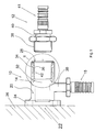
Fig. 1 zeigt zwei Rohrleitungselemente 10,12, die als Pressfittinge ausgebildet
sind und zu unterschiedlichen Leitungssystemen gehören. So handelt es
sich bei dem Rohrleitungselement 10 um einen Kunststofffitting mit einem
Kunststoff-Grundkörper 14, der als Winkelrohrelement ausgebildet ist. An
dem Grundkörper 14 befindet sich eine Stützhülse 18 aus Kunststoff, auf die
ein Kunststoffrohr bzw. Kunststoff-Metall-Verbundrohr aufpressbar ist. Der
Grundkörper 14 weist ein Rohrstück 20 auf, von dem der Stützkörper 18
radial absteht und das an einem Ende 22 verschlossen ist. An diesem Ende
22 weist das Rohrstück 20 einen Flansch 24 auf, mit dem das Rohrstück 20
und damit das gesamte Rohrleitungselement 10 an einer Wand 26 befestigbar
ist. Das dem verschlossenen Ende 22 gegenüberliegende Ende 28 des
Rohrstücks 20 ist offen und dient der Aufnahme des Fitting-Rohrleitungselements
12. Durch die Kunststoff-Stützhülse 18 und das Kunststoff-Rohrstück
20 erstrecken sich Durchlässe 30,32, die untereinander in Verbindung
stehen. In das offene Ende 28 des Rohrstücks 20 des Grundkörpers 14 ist
ein Metall-Anschlusskörper 34 eingesetzt, der ein Innengewinde 36 aufweist,
mit dem das Außengewinde 38 an dem Fittingkörper 40 des Fitting-Rohrleitungselements
12 verschraubbar ist. Der Fittingkörper 40 weist eine
Stützhülse 41 auf, auf die ein Rohr aufpressbar ist.Fig. 1 shows two
Mit den beiden Rohrleitungselementen 10,12 gemäß Fig. 1 lässt sich ein
Übergang zwischen einem Kunststofffittingsystem zu einem Metallfitting-system
realisieren. Da das Kunststoffmaterial des Grundkörpers 14 des
Rohrleitungselements 10 keine ausreichende Scherfestigkeit aufweist, erfolgt
die Schraubverbindung zum aus Metall bestehenden Fitting-Rohrleitungselement
12 durch den in dem Grundkörper 14 eingebetteten Metall-Anschlusskörper
34, der sozusagen die Anschlussfläche 42 zum Anschließen
des aus Metall bestehenden Fitting-Rohrleitungselements 12 bildet. Diese
Anschlussfläche 42 ist in diesem Fall als Innengewinde 36 ausgebildet, das
dann mit dem Außengewinde 38 des Fitting-Rohrleitungselements 12 zusammenwirkt.
Ebenso ist es aber auch denkbar, dass der Metall-Anschlusskörper
34 außen am Rohrleitungselement 10 angeordnet ist und dann ein
Außengewinde aufweist, das mit einem Innengewinde eines mit dem Rohrleitungselement
10 verschraubbaren Rohrleitungselements versehen ist.One can use the two
Als Material für den Grundkörper 14 kommt ein hochtemperaturfester
amorpher Kunststoff, wie beispielsweise PSU oder PPSU in Frage, der DVGW
zugelassen ist. Ebenso bestehen der Metall-Anschlusskörper 34 sowie das
Fitting-Rohrleitungselement 12 aus einem Metall bzw. Metalllegierung, das
bzw. die ebenfalls nach DVGW zugelassen ist.A high-temperature resistant material comes as the material for the
Anhand von Fig. 2 wird nachfolgend genauer auf die Abdichtung des Grundkörpers
14 gegenüber dem Metall-Anschlusskörper 34 des Rohrleitungselements
10 eingegangen. Beide Körper 14,34 liegen entlang von Grenzflächen
44,46 aneinander. In der Grenzfläche 46 des Metall-Anschlusskörpers 34
sind mehrere in Umfangsrichtung umlaufende Nuten 48 eingearbeitet, in die
Vorsprünge 50 des Grundkörpers 14 eingreifen. Darüber hinaus weist der
Metall-Anschlusskörper 34 eine weitere außenliegende (Aufnahme-)Nut 52
auf, in der sich ein ringförmiges Dichtelement 54 befindet. Das Dichtelement
54 besteht aus einem Dichtwerkstoff, der einen niedrigeren E-Modul
aufweist als das Kunststoffmaterial des Grundkörpers 14. Das Dichtelement
54 ist nach Art eines Bandringes ausgebildet und weist eine innenliegende
Anlagefläche 56 sowie eine außenliegende Anlagefläche 58 auf. Die innenliegende
Anlagefläche 56 liegt dabei an dem Grund 60 der Aufnahmenut 52
an, während die außenliegende Anlagefläche 58 an der Grenzfläche 44 des
Grundkörpers 14 anliegt. An den axialen Stirnenden 62 liegt das Dichtelement
54 an den Flanken 64 der Aufnahmenut 52 an.With reference to FIG. 2, the sealing of the base body is described in more detail below
14 with respect to the
Das Dichtelement 54 befindet sich unter Vorspannung und drückt damit mit
einer gewissen Andrückkraft an seinen Anlageflächen 56,58 gegen den
Metall-Anschlusskörper 34 bzw. den Grundkörper 14. Durch die Vorspannung
bleiben die Anlageflächen 56,58 des Dichtelements 54 auch dann an
den Grenzflächen 44,46 in Anlage, wenn sich zwischen den Grenzflächen im
Laufe der Zeit, wenn auch nur im mikroskopischen Maßstab, Ablösungen
(Kapillare) einstellen. Damit ist die Verbindung zwischen dem Grundkörper
14 aus Kunststoff und dem Anschlusskörper 34 aus Metall über die gesamte
Betriebsdauer des Rohrleitungselements 10 mediendicht.The sealing
Zusätzlich ist in einer weiteren außenliegenden (Aufnahme-)Nut 67 des
Metall-Anschlusskörpers 34 ein zweites Dichtelement 68 angeordnet, das
aus einem bei Kontakt mit Feuchtigkeit expandierenden Dichtmaterial besteht.
Dieses zweite Dichtelement 68 sichert die Grenzschicht zwischen dem
Grundkörper 14 und dem Metall-Anschlusskörper 34 in dem Fall ab, dass
das Dichtelement 54 aus welchen Gründen auch immer nicht vollständig abdichten
sollte (zusätzliche Abdichtungssicherheit).In addition, in a further external (receiving)
Durch die ineinandergreifenden Nuten 48 und Vorsprünge 50 kommt es zwischen
dem Metall-Anschlusskörper 34 und dem Grundkörper 14 zu einer
bezüglich axialer Kräfte kraftschlüssigen Verbindung durch Formschluss. Wie
anhand der Figuren zu erkennen ist, ist das innenliegende axiale Ende 66
des im wesentlichen hülsenförmigen Anschlusskörpers 34 sowohl an der
Außen- als auch an der Innenseite vom Material des Grundkörpers 14 umschlossen.
Sowohl auf der Außenseite als auch auf der Innenseite weist der
Metall-Anschlusskörper 34 Vorsprünge 69 auf, wobei der Vorsprung 69 auf
der Innenseite von einem Vorsprung 70 des Grundkörpers 14 umgriffen ist.
Am innenliegenden Ende 66 des Anschlusskörpers 34 wird dessen Grenzfläche
46 einerseits von der Außenseite als auch von der Innenseite des
Anschlusskörpers 34 gebildet. Genauso wird in diesem Bereich die Grenzfläche
44 des Grundkörpers 14 von dessen radial einwärts gerichteten
Flächenabschnitt und dem Flächenabschnitt im Bereich des Vorsprungs 70
gebildet.Due to the interlocking
Fign. 3 und 4 zeigen alternative Ausgestaltungen von Dichtelementen
54',54". Gemäß Fig. 3 weist das Dichtelement 54' an seiner radial innenliegenden
Anlagefläche 56 eine Verzahnung in Form von V-förmigen Rippen 72
mit dazwischenliegenden V-förmigen Nuten 74. Ferner ist das Dichtelement
54' mit einer Versteifungsseele 76 aus insbesondere Metall versehen. An
den stirnseitigen Enden 62 weist das Dichtelement 54' einen Rundungsradius
auf, der größer ist als der Rundungsradius im Eckenbereich 78 zwischen
den Flanken 64 und dem Grund 60 der Aufnahmenut 52 im Metall-Anschlusskörper
34.Fig. 3 and 4 show alternative configurations of sealing
Auf der dem Grundkörper 14 zugewandten außenliegenden Anlageseite 58
weist das Dichtelement 54' eine Verzahnung mit flach verlaufenden Vorsprüngen
80 und weiter vorstehenden Vorsprünge 82,84 auf. Diese beiden
letztgenannten Vorsprünge 82,84 dienen der Verstärkung der Anlage des
Dichtelements 54' sowohl am Grundkörper 14 als auch in der Aufnahmenut
52 des Anschlusskörpers 34. In diesem Zusammenhang sei erwähnt, dass
das Rohrleitungselement 10 durch Umspritzen des Anschlusskörpers 34 mit
dem Kunststoffmaterial des Grundkörpers 14 hergestellt wird. Die Fließ-richtung
der Kunststoffschmelze ist in Fig. 3 mit dem Pfeil 86 angedeutet.
Zu erkennen ist, dass die Vorsprünge 82,84 in Richtung des Pfeils 86 zur
Seite geneigt von der Anlagefläche 58 des Dichtelements 54' abstehen.
Fließt nun das Kunststoffmaterial an diesen Vorsprüngen 82,84 vorbei, so
wird auf diese eine Biegekraft in Richtung des Anschlusskörpers 34 ausgeübt.
Dadurch wird die Kompressibilität des Dichtelements 54' weiter erhöht.
Ohne eine solche Ausbildung der Anlagefläche 58 (s. das Ausführungsbeispiel
gemäß Fig. 2) wird der Füll- bzw. Nachpressdruck der Kunststoffschmelze
durch die sich über die Anlagefläche 58 einstellende Anpresskraft
in eine Komprimierung des Materials des Dichtelements 54' umgesetzt. Mit
den schrägverlaufenden Vorsprüngen 82,84 kann diese Kompression des
Dichtelements 54' noch erhöht werden.On the
Fig. 4 zeigt eine Variante des Dichtelements 54' der Fig. 3. Das Dichtelement
54" von Fig. 4 weist symmetrisch zu einer Mittelebene 88 angeordnete,
voneinander weg weisende schrägverlaufende Vorsprünge 82",84"
auf, die symmetrisch zu einer Kunststoffschmelzeneinfüllstelle (bei 90 angedeutet)
angeordnet sind, über die die Kunststoffschmelze entlang der Pfeile
92 an der Anlagefläche 58 des Dichtelements 54" entlangströmt. Auch hier
tritt wieder der Effekt der Erhöhung der Komprimierung des Dichtelements
54" durch Umlegen der Vorsprünge 82",84" ein.FIG. 4 shows a variant of the sealing element 54 'of FIG. 3. The sealing element
4 "of FIG. 4 has symmetrical arrangements about a
Claims (21)
Applications Claiming Priority (2)
| Application Number | Priority Date | Filing Date | Title |
|---|---|---|---|
| DE19957601 | 1999-11-30 | ||
| DE19957601A DE19957601C2 (en) | 1999-11-30 | 1999-11-30 | Pipe element with a connection surface for connecting to another pipe element |
Publications (3)
| Publication Number | Publication Date |
|---|---|
| EP1106899A2 true EP1106899A2 (en) | 2001-06-13 |
| EP1106899A3 EP1106899A3 (en) | 2003-06-04 |
| EP1106899B1 EP1106899B1 (en) | 2005-10-26 |
Family
ID=7930859
Family Applications (1)
| Application Number | Title | Priority Date | Filing Date |
|---|---|---|---|
| EP00126130A Expired - Lifetime EP1106899B1 (en) | 1999-11-30 | 2000-11-30 | Pipe section provided with a coupling surface for connecting it to another pipe section |
Country Status (4)
| Country | Link |
|---|---|
| EP (1) | EP1106899B1 (en) |
| AT (1) | ATE308011T1 (en) |
| DE (2) | DE19957601C2 (en) |
| ES (1) | ES2248006T3 (en) |
Cited By (1)
| Publication number | Priority date | Publication date | Assignee | Title |
|---|---|---|---|---|
| FR2930313A1 (en) * | 2008-04-21 | 2009-10-23 | Hutchinson Sa | CONNECTING DEVICE, ITS ASSEMBLY METHOD AND AIR CONDITIONING CIRCUIT OR ASSISTED STEERING CIRCUIT INCORPORATING THE SAME. |
Families Citing this family (2)
| Publication number | Priority date | Publication date | Assignee | Title |
|---|---|---|---|---|
| DE102006051774A1 (en) | 2006-11-03 | 2008-05-08 | Uponor Innovation Ab | Fitting for a pipe |
| DE202007011565U1 (en) * | 2007-08-17 | 2009-01-02 | Rehau Ag + Co | pipe arrangement |
Family Cites Families (5)
| Publication number | Priority date | Publication date | Assignee | Title |
|---|---|---|---|---|
| JPS51160216U (en) * | 1975-06-14 | 1976-12-20 | ||
| DE8406562U1 (en) * | 1984-03-02 | 1984-08-30 | Jeschke, Immanuel, 3203 Sarstedt | TRANSITION PIECE IN A GAS PIPE |
| DE8800282U1 (en) * | 1988-01-13 | 1988-02-25 | Manibs Spezialarmaturen Gmbh & Co Kg, 5630 Remscheid, De | |
| US5172919A (en) * | 1990-02-22 | 1992-12-22 | C. I. Kasei Co., Ltd. | Appliance for preventing water from leaking through joint |
| GB2273537B (en) * | 1992-12-17 | 1996-01-31 | Yong Goo Shin | Ring packing |
-
1999
- 1999-11-30 DE DE19957601A patent/DE19957601C2/en not_active Expired - Fee Related
-
2000
- 2000-11-30 DE DE50011430T patent/DE50011430D1/en not_active Expired - Lifetime
- 2000-11-30 EP EP00126130A patent/EP1106899B1/en not_active Expired - Lifetime
- 2000-11-30 ES ES00126130T patent/ES2248006T3/en not_active Expired - Lifetime
- 2000-11-30 AT AT00126130T patent/ATE308011T1/en not_active IP Right Cessation
Non-Patent Citations (1)
| Title |
|---|
| None |
Cited By (2)
| Publication number | Priority date | Publication date | Assignee | Title |
|---|---|---|---|---|
| FR2930313A1 (en) * | 2008-04-21 | 2009-10-23 | Hutchinson Sa | CONNECTING DEVICE, ITS ASSEMBLY METHOD AND AIR CONDITIONING CIRCUIT OR ASSISTED STEERING CIRCUIT INCORPORATING THE SAME. |
| EP2112417A1 (en) | 2008-04-21 | 2009-10-28 | Hutchinson | Connection device |
Also Published As
| Publication number | Publication date |
|---|---|
| DE19957601A1 (en) | 2001-06-07 |
| DE50011430D1 (en) | 2005-12-01 |
| EP1106899A3 (en) | 2003-06-04 |
| EP1106899B1 (en) | 2005-10-26 |
| ATE308011T1 (en) | 2005-11-15 |
| DE19957601C2 (en) | 2001-09-13 |
| ES2248006T3 (en) | 2006-03-16 |
Similar Documents
| Publication | Publication Date | Title |
|---|---|---|
| DE2724793A1 (en) | SEALING DEVICE | |
| DE19706921A1 (en) | Disc, in particular the face plate of a filter insert | |
| EP1391640A1 (en) | Sealing ring | |
| EP2530363B1 (en) | Seal and housing with such a seal | |
| DE102017118162A1 (en) | Connecting device for pipelines with leakage indicator | |
| DE19651817A1 (en) | Pipe press coupling | |
| EP2404097B1 (en) | Connecting system for connecting a pipe to a main pipe | |
| DE2024840A1 (en) | Sealing construction for pipe connections | |
| EP1881251B1 (en) | Gasket and connecting device for a socket joint | |
| DE10252141A1 (en) | Flat sealing ring | |
| EP1389691A1 (en) | Plastic nut for mounting at a construction unit | |
| DE1925171A1 (en) | Connection device or coupling | |
| EP1106899B1 (en) | Pipe section provided with a coupling surface for connecting it to another pipe section | |
| EP0565957B1 (en) | Connection piece for a pipe | |
| DE102014108108B4 (en) | Gas sealing mechanism with a sealing body | |
| DE102016219889A1 (en) | seal | |
| DE202012004630U1 (en) | Concrete pipe with plastic outer lining | |
| DE19946133A1 (en) | Lip sealing ring for pipe joints comprises circumferential sealing lips which radially protrude outwards and/or inwards from ring body element | |
| DE10047758A1 (en) | Insert unit for an opening, in particular, in a pipe-shaped hollow component comprises a flexible sealing element which expands radially when subjected to an axial tightening force | |
| DE102018109998A1 (en) | Pipe connection system and method for producing a pipe connection | |
| DE4441348A1 (en) | Connection of flange at end of pipe to flat counter=part esp. for plastics pipes | |
| DE19943473B4 (en) | sealing device | |
| WO2018036841A1 (en) | Seal assembly and valve assembly | |
| EP0347608B1 (en) | Sealing ring | |
| DE102004063973A1 (en) | Seal assembly for a valve |
Legal Events
| Date | Code | Title | Description |
|---|---|---|---|
| PUAI | Public reference made under article 153(3) epc to a published international application that has entered the european phase |
Free format text: ORIGINAL CODE: 0009012 |
|
| AK | Designated contracting states |
Kind code of ref document: A2 Designated state(s): AT BE CH CY DE DK ES FI FR GB GR IE IT LI LU MC NL PT SE TR |
|
| AX | Request for extension of the european patent |
Free format text: AL;LT;LV;MK;RO;SI |
|
| RAP1 | Party data changed (applicant data changed or rights of an application transferred) |
Owner name: UPONOR INNOVATION AB |
|
| PUAL | Search report despatched |
Free format text: ORIGINAL CODE: 0009013 |
|
| AK | Designated contracting states |
Designated state(s): AT BE CH CY DE DK ES FI FR GB GR IE IT LI LU MC NL PT SE TR |
|
| AX | Request for extension of the european patent |
Extension state: AL LT LV MK RO SI |
|
| 17P | Request for examination filed |
Effective date: 20030919 |
|
| AKX | Designation fees paid |
Designated state(s): AT BE CH CY DE DK ES FI FR GB GR IE IT LI LU MC NL PT SE TR |
|
| 17Q | First examination report despatched |
Effective date: 20040211 |
|
| GRAP | Despatch of communication of intention to grant a patent |
Free format text: ORIGINAL CODE: EPIDOSNIGR1 |
|
| GRAS | Grant fee paid |
Free format text: ORIGINAL CODE: EPIDOSNIGR3 |
|
| GRAA | (expected) grant |
Free format text: ORIGINAL CODE: 0009210 |
|
| AK | Designated contracting states |
Kind code of ref document: B1 Designated state(s): AT BE CH CY DE DK ES FI FR GB GR IE IT LI LU MC NL PT SE TR |
|
| PG25 | Lapsed in a contracting state [announced via postgrant information from national office to epo] |
Ref country code: NL Free format text: LAPSE BECAUSE OF FAILURE TO SUBMIT A TRANSLATION OF THE DESCRIPTION OR TO PAY THE FEE WITHIN THE PRESCRIBED TIME-LIMIT Effective date: 20051026 Ref country code: TR Free format text: LAPSE BECAUSE OF FAILURE TO SUBMIT A TRANSLATION OF THE DESCRIPTION OR TO PAY THE FEE WITHIN THE PRESCRIBED TIME-LIMIT Effective date: 20051026 Ref country code: FI Free format text: LAPSE BECAUSE OF FAILURE TO SUBMIT A TRANSLATION OF THE DESCRIPTION OR TO PAY THE FEE WITHIN THE PRESCRIBED TIME-LIMIT Effective date: 20051026 Ref country code: IE Free format text: LAPSE BECAUSE OF FAILURE TO SUBMIT A TRANSLATION OF THE DESCRIPTION OR TO PAY THE FEE WITHIN THE PRESCRIBED TIME-LIMIT Effective date: 20051026 |
|
| REG | Reference to a national code |
Ref country code: GB Ref legal event code: FG4D Free format text: NOT ENGLISH |
|
| REG | Reference to a national code |
Ref country code: CH Ref legal event code: EP |
|
| PGFP | Annual fee paid to national office [announced via postgrant information from national office to epo] |
Ref country code: FR Payment date: 20051110 Year of fee payment: 6 |
|
| PG25 | Lapsed in a contracting state [announced via postgrant information from national office to epo] |
Ref country code: CY Free format text: LAPSE BECAUSE OF FAILURE TO SUBMIT A TRANSLATION OF THE DESCRIPTION OR TO PAY THE FEE WITHIN THE PRESCRIBED TIME-LIMIT Effective date: 20051130 Ref country code: AT Free format text: LAPSE BECAUSE OF NON-PAYMENT OF DUE FEES Effective date: 20051130 Ref country code: BE Free format text: LAPSE BECAUSE OF NON-PAYMENT OF DUE FEES Effective date: 20051130 Ref country code: LI Free format text: LAPSE BECAUSE OF NON-PAYMENT OF DUE FEES Effective date: 20051130 Ref country code: CH Free format text: LAPSE BECAUSE OF NON-PAYMENT OF DUE FEES Effective date: 20051130 Ref country code: MC Free format text: LAPSE BECAUSE OF NON-PAYMENT OF DUE FEES Effective date: 20051130 |
|
| REG | Reference to a national code |
Ref country code: IE Ref legal event code: FG4D Free format text: LANGUAGE OF EP DOCUMENT: GERMAN |
|
| REF | Corresponds to: |
Ref document number: 50011430 Country of ref document: DE Date of ref document: 20051201 Kind code of ref document: P |
|
| PG25 | Lapsed in a contracting state [announced via postgrant information from national office to epo] |
Ref country code: LU Free format text: LAPSE BECAUSE OF NON-PAYMENT OF DUE FEES Effective date: 20051226 |
|
| PG25 | Lapsed in a contracting state [announced via postgrant information from national office to epo] |
Ref country code: DK Free format text: LAPSE BECAUSE OF FAILURE TO SUBMIT A TRANSLATION OF THE DESCRIPTION OR TO PAY THE FEE WITHIN THE PRESCRIBED TIME-LIMIT Effective date: 20060126 Ref country code: GR Free format text: LAPSE BECAUSE OF FAILURE TO SUBMIT A TRANSLATION OF THE DESCRIPTION OR TO PAY THE FEE WITHIN THE PRESCRIBED TIME-LIMIT Effective date: 20060126 |
|
| REG | Reference to a national code |
Ref country code: SE Ref legal event code: TRGR |
|
| GBT | Gb: translation of ep patent filed (gb section 77(6)(a)/1977) |
Effective date: 20060213 |
|
| REG | Reference to a national code |
Ref country code: ES Ref legal event code: FG2A Ref document number: 2248006 Country of ref document: ES Kind code of ref document: T3 |
|
| PG25 | Lapsed in a contracting state [announced via postgrant information from national office to epo] |
Ref country code: PT Free format text: LAPSE BECAUSE OF FAILURE TO SUBMIT A TRANSLATION OF THE DESCRIPTION OR TO PAY THE FEE WITHIN THE PRESCRIBED TIME-LIMIT Effective date: 20060327 |
|
| NLV1 | Nl: lapsed or annulled due to failure to fulfill the requirements of art. 29p and 29m of the patents act | ||
| REG | Reference to a national code |
Ref country code: IE Ref legal event code: FD4D |
|
| REG | Reference to a national code |
Ref country code: CH Ref legal event code: PL |
|
| PLBE | No opposition filed within time limit |
Free format text: ORIGINAL CODE: 0009261 |
|
| STAA | Information on the status of an ep patent application or granted ep patent |
Free format text: STATUS: NO OPPOSITION FILED WITHIN TIME LIMIT |
|
| 26N | No opposition filed |
Effective date: 20060727 |
|
| EN | Fr: translation not filed | ||
| PG25 | Lapsed in a contracting state [announced via postgrant information from national office to epo] |
Ref country code: FR Free format text: LAPSE BECAUSE OF FAILURE TO SUBMIT A TRANSLATION OF THE DESCRIPTION OR TO PAY THE FEE WITHIN THE PRESCRIBED TIME-LIMIT Effective date: 20061215 |
|
| BERE | Be: lapsed |
Owner name: UPONOR INNOVATION A.B. Effective date: 20051130 |
|
| PGFP | Annual fee paid to national office [announced via postgrant information from national office to epo] |
Ref country code: DE Payment date: 20121121 Year of fee payment: 13 |
|
| PGFP | Annual fee paid to national office [announced via postgrant information from national office to epo] |
Ref country code: SE Payment date: 20121120 Year of fee payment: 13 Ref country code: IT Payment date: 20121128 Year of fee payment: 13 Ref country code: GB Payment date: 20121120 Year of fee payment: 13 Ref country code: ES Payment date: 20121122 Year of fee payment: 13 |
|
| GBPC | Gb: european patent ceased through non-payment of renewal fee |
Effective date: 20131130 |
|
| REG | Reference to a national code |
Ref country code: SE Ref legal event code: EUG |
|
| REG | Reference to a national code |
Ref country code: DE Ref legal event code: R119 Ref document number: 50011430 Country of ref document: DE Effective date: 20140603 |
|
| PG25 | Lapsed in a contracting state [announced via postgrant information from national office to epo] |
Ref country code: DE Free format text: LAPSE BECAUSE OF NON-PAYMENT OF DUE FEES Effective date: 20140603 Ref country code: SE Free format text: LAPSE BECAUSE OF NON-PAYMENT OF DUE FEES Effective date: 20131201 Ref country code: IT Free format text: LAPSE BECAUSE OF NON-PAYMENT OF DUE FEES Effective date: 20131130 |
|
| PG25 | Lapsed in a contracting state [announced via postgrant information from national office to epo] |
Ref country code: GB Free format text: LAPSE BECAUSE OF NON-PAYMENT OF DUE FEES Effective date: 20131130 |
|
| REG | Reference to a national code |
Ref country code: ES Ref legal event code: FD2A Effective date: 20150407 |
|
| PG25 | Lapsed in a contracting state [announced via postgrant information from national office to epo] |
Ref country code: ES Free format text: LAPSE BECAUSE OF NON-PAYMENT OF DUE FEES Effective date: 20131201 |