EP1106860A1 - Elastomer vibration isolator bushing - Google Patents
Elastomer vibration isolator bushing Download PDFInfo
- Publication number
- EP1106860A1 EP1106860A1 EP00308317A EP00308317A EP1106860A1 EP 1106860 A1 EP1106860 A1 EP 1106860A1 EP 00308317 A EP00308317 A EP 00308317A EP 00308317 A EP00308317 A EP 00308317A EP 1106860 A1 EP1106860 A1 EP 1106860A1
- Authority
- EP
- European Patent Office
- Prior art keywords
- elastomer
- bond
- outer metal
- cylinders
- bushing
- Prior art date
- Legal status (The legal status is an assumption and is not a legal conclusion. Google has not performed a legal analysis and makes no representation as to the accuracy of the status listed.)
- Granted
Links
- 229920001971 elastomer Polymers 0.000 title claims abstract description 53
- 239000000806 elastomer Substances 0.000 title claims abstract description 50
- 239000002184 metal Substances 0.000 claims abstract description 32
- 230000006835 compression Effects 0.000 claims abstract description 6
- 238000007906 compression Methods 0.000 claims abstract description 6
- 239000000463 material Substances 0.000 claims abstract description 4
- 238000000034 method Methods 0.000 claims description 6
- 238000002955 isolation Methods 0.000 claims description 5
- 229910001220 stainless steel Inorganic materials 0.000 claims description 2
- 239000010935 stainless steel Substances 0.000 claims description 2
- 239000013536 elastomeric material Substances 0.000 claims 4
- 230000008878 coupling Effects 0.000 claims 2
- 238000010168 coupling process Methods 0.000 claims 2
- 238000005859 coupling reaction Methods 0.000 claims 2
- 239000004593 Epoxy Substances 0.000 description 2
- 238000000926 separation method Methods 0.000 description 2
- 229910000831 Steel Inorganic materials 0.000 description 1
- 238000013016 damping Methods 0.000 description 1
- 229920006351 engineering plastic Polymers 0.000 description 1
- 239000007787 solid Substances 0.000 description 1
- 239000010959 steel Substances 0.000 description 1
Images
Classifications
-
- F—MECHANICAL ENGINEERING; LIGHTING; HEATING; WEAPONS; BLASTING
- F16—ENGINEERING ELEMENTS AND UNITS; GENERAL MEASURES FOR PRODUCING AND MAINTAINING EFFECTIVE FUNCTIONING OF MACHINES OR INSTALLATIONS; THERMAL INSULATION IN GENERAL
- F16F—SPRINGS; SHOCK-ABSORBERS; MEANS FOR DAMPING VIBRATION
- F16F1/00—Springs
- F16F1/36—Springs made of rubber or other material having high internal friction, e.g. thermoplastic elastomers
- F16F1/38—Springs made of rubber or other material having high internal friction, e.g. thermoplastic elastomers with a sleeve of elastic material between a rigid outer sleeve and a rigid inner sleeve or pin, i.e. bushing-type
- F16F1/3863—Springs made of rubber or other material having high internal friction, e.g. thermoplastic elastomers with a sleeve of elastic material between a rigid outer sleeve and a rigid inner sleeve or pin, i.e. bushing-type characterised by the rigid sleeves or pin, e.g. of non-circular cross-section
Definitions
- the present invention relates to elastomer bushings and particularly to improving the bushing life of elastomer bushings used in mechanical system components.
- Elastomer bushings are used in oil tank mount systems to dampen resonances and reduce vibratory loads on tank and brackets.
- the elastomer is effective in detuning resonances in the engine operating range.
- the elastomer bushings are constructed of two concentric metal cylinders, with an epoxy or other rubber member interposed between the cylinders.
- the metal cylinders provide necessary rigidity to the bushing.
- the elastomer or rubber provides the required spring rate and decoupling/vibration isolation between the structures.
- an elastomer bushing may be used between oil tank and engine frame structures. In operation, the relative motion between oil tank and engine frame, or other structures, induces shear loads on the elastomer to metal cylinder bonds of the bushing. This causes the bond to deliminate or fail over time.
- the present invention proposes reducing shear load on the elastomer epoxy bond to metal cylinders. This is accomplished by adding end lugs to inner and outer cylinders of the bushing.
- An elastomer bushing is provided for use with mechanical system components that require resonance dampening and vibratory load reduction.
- the elastomer bushing component comprises two concentric metal cylinders with elastomer epoxied to the cylinders.
- the metal cylinders provide rigidity to the bushing and the elastomer provides vibration isolation.
- end lugs are added to inner and outer cylinders of the bushing.
- the present invention provides an effective technique for improving bushing life for mechanical system components.
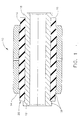
- the bushing assembly 10 is typically comprised of inner and outer concentric metal sleeves or cylinders 12 and 14, respectively.
- a rubber or other elastomer material 16 is disposed between the two cylinders 12 and 14.
- one cylinder is joined to a movable member and the other cylinder is joined to a support element.
- the bushing is constructed to permit controlled movement between parts, and to decouple translational and rotational vibrational modes for damping and isolation.
- the inner cylinder 12 is of an internal diameter chosen to facilitate its mounting requirements.
- inner member 12 may be solid or rod-like rather than hollow. While the inner member 12 is commonly made of a metal such as steel, it may also be fabricated from an engineering plastic.
- the internal diameter of the elastomer member 16 is somewhat less than the outer diameter of the rigid inner member 12. When in an assembled condition, this insures that the fit between the inner member 12 and the elastomeric member 16 forms a proper seal. Additionally, the elastomeric member 16 must interface with the outer member 14 to form the desired seal.
- the present invention proposes the addition of end lugs 18 to the inner and outer cylinders 12 and 14 of the bushing 10.
- the end lugs are integral with the inner and outer cylinders 12 and 14, with the entire unit typically manufactured from stainless steel.
- the end lugs 18 reduce the shear load on the elastomer bond 20 to the metal cylinders 12 and 14.
- the relative motion between cylinders 14 and 12 induces separation or shear load in the elastomer to cylinder bond 20.
- part of this elastomer separation load is taken up into compression of the elastomer.
- the total shear load is reduced by the amount of compression.
- the end lugs 18 provide a face for the elastomer to bear on.
- the addition of end lugs to be integral with the cylinders provides the desired load carrying capacity.
Landscapes
- Engineering & Computer Science (AREA)
- General Engineering & Computer Science (AREA)
- Mechanical Engineering (AREA)
- Springs (AREA)
- Vibration Prevention Devices (AREA)
- Insulators (AREA)
Abstract
Description
- The present invention relates to elastomer bushings and particularly to improving the bushing life of elastomer bushings used in mechanical system components.
- Elastomer bushings are used in oil tank mount systems to dampen resonances and reduce vibratory loads on tank and brackets. The elastomer is effective in detuning resonances in the engine operating range. The elastomer bushings are constructed of two concentric metal cylinders, with an epoxy or other rubber member interposed between the cylinders. The metal cylinders provide necessary rigidity to the bushing. The elastomer or rubber provides the required spring rate and decoupling/vibration isolation between the structures. For example, then, an elastomer bushing may be used between oil tank and engine frame structures. In operation, the relative motion between oil tank and engine frame, or other structures, induces shear loads on the elastomer to metal cylinder bonds of the bushing. This causes the bond to deliminate or fail over time.
- It would be desirable, then, to improve the bushing life of elastomer bushings used to dampen resonances and reduce vibratory loads in mechanical system
- To improve bushing life, the present invention proposes reducing shear load on the elastomer epoxy bond to metal cylinders. This is accomplished by adding end lugs to inner and outer cylinders of the bushing.
- An elastomer bushing is provided for use with mechanical system components that require resonance dampening and vibratory load reduction. The elastomer bushing component comprises two concentric metal cylinders with elastomer epoxied to the cylinders. The metal cylinders provide rigidity to the bushing and the elastomer provides vibration isolation. To reduce shear load on the elastomer, end lugs are added to inner and outer cylinders of the bushing.
- Accordingly, the present invention provides an effective technique for improving bushing life for mechanical system components.
- The invention will now be described in greater detail, by way of example, with reference to the drawing, the single figure of which illustrates an elastomer bushing constructed in accordance with the teachings of the present invention.
- Referring to Fig. 1, there is illustrated an
elastomeric bushing assembly 10. Thebushing assembly 10 is typically comprised of inner and outer concentric metal sleeves orcylinders other elastomer material 16 is disposed between the twocylinders - The
inner cylinder 12 is of an internal diameter chosen to facilitate its mounting requirements. In some applicationsinner member 12 may be solid or rod-like rather than hollow. While theinner member 12 is commonly made of a metal such as steel, it may also be fabricated from an engineering plastic. - The internal diameter of the
elastomer member 16 is somewhat less than the outer diameter of the rigidinner member 12. When in an assembled condition, this insures that the fit between theinner member 12 and theelastomeric member 16 forms a proper seal. Additionally, theelastomeric member 16 must interface with theouter member 14 to form the desired seal. - The present invention proposes the addition of
end lugs 18 to the inner andouter cylinders bushing 10. The end lugs are integral with the inner andouter cylinders end lugs 18 reduce the shear load on theelastomer bond 20 to themetal cylinders cylinders cylinder bond 20. With the addition of end lugs, part of this elastomer separation load is taken up into compression of the elastomer. The total shear load is reduced by the amount of compression. Hence, theend lugs 18 provide a face for the elastomer to bear on. The addition of end lugs to be integral with the cylinders provides the desired load carrying capacity. - While the invention has been described with reference to a preferred embodiment, it will be understood by those skilled in the art that various changes may be made and equivalents may be substituted for elements thereof without departing from the scope of the invention. For example, this design can be applied in various environments to various components.
Claims (11)
- A structure (10) for reducing shear load on an elastomer bond (20), the structure comprising:an inner metal cylinder (12) coupled to a first component;an outer metal cylinder (14) coupled to a second component;an elastomer material (16) disposed between the inner and outer metal cylinders (12, 14) to create an elastomer bond (20); andend lugs (18) integral with the inner and outer metal cylinders (12, 14) to reduce the shear load on the elastomer bond (20) by taking up elastomer load into compression of the elastomer (16).
- A structure (10) as claimed in claim 1 wherein the elastomer bond (20) provides vibration isolation between the first and second components.
- A structure (10) as claimed in claim 1 or 2 wherein the inner and outer metal cylinders (12, 14) integral with the end lugs (18) are comprised of stainless steel.
- A structure (10) as claimed in claim 1, 2 or 3 wherein an internal diameter of the elastomer material (16) is less than an outer diameter of the inner metal cylinder (12).
- An elastomer bushing (10) comprising:an inner metal cylinder (12);an outer metal cylinder (14) concentric with the inner metal cylinder (12);an elastomeric material (16) to create an elastomer-to-metal-cylinder bond (20) between the inner and outer metal cylinders (12, 14); andend lugs (18) integral with the inner and outer metal cylinders (12, 14) to provide a surface for the elastomeric material (16) to bear on.
- An elastomer bushing (10) as claimed in claim 5 wherein the elastomeric material (16) interfaces with the inner and outer metal cylinders (12, 14) to form a seal.
- An elastomer bushing (10) as claimed in claim 5 or 6 wherein the end lugs (18) reduce shear load on the elastomer-to-metal-cylinder bond (20) by taking some shear load into compression of the elastomeric material (16).
- A method for reducing shear load on an elastomer bond (20), the method comprising the steps of:providing an inner metal cylinder (12) and an outer metal cylinder (14);coupling the inner metal cylinder (12) to a first component;coupling the outer metal cylinder (14) to a second component;inserting an elastomer (16) between the inner and outer metal cylinders (12, 14) to create the elastomer bond (20); andforming end lugs (18) integral with the inner and outer metal cylinders (12, 14) to reduce the shear load on the elastomer bond (20).
- A method as claimed in claim 8 further comprising the step of taking up elastomer load into compression of the elastomer (16).
- A method as claimed in claim 8 or 9 further comprising the step of using the elastomer (16) to provide vibration isolation between the first and second components.
- A method as claimed in claim 8, 9 or 10 further comprising the step of forming an internal diameter of the elastomer (16) to be less than an outer diameter of the inner metal cylinder (12).
Applications Claiming Priority (2)
| Application Number | Priority Date | Filing Date | Title |
|---|---|---|---|
| US45128099A | 1999-11-30 | 1999-11-30 | |
| US451280 | 1999-11-30 |
Publications (2)
| Publication Number | Publication Date |
|---|---|
| EP1106860A1 true EP1106860A1 (en) | 2001-06-13 |
| EP1106860B1 EP1106860B1 (en) | 2004-12-01 |
Family
ID=23791574
Family Applications (1)
| Application Number | Title | Priority Date | Filing Date |
|---|---|---|---|
| EP00308317A Expired - Lifetime EP1106860B1 (en) | 1999-11-30 | 2000-09-22 | Elastomer vibration isolator bushing |
Country Status (5)
| Country | Link |
|---|---|
| EP (1) | EP1106860B1 (en) |
| JP (1) | JP2001214950A (en) |
| AT (1) | ATE283987T1 (en) |
| DE (1) | DE60016364T2 (en) |
| ES (1) | ES2233296T3 (en) |
Families Citing this family (2)
| Publication number | Priority date | Publication date | Assignee | Title |
|---|---|---|---|---|
| JP4699294B2 (en) * | 2006-06-15 | 2011-06-08 | 倉敷化工株式会社 | Vibration isolator |
| CN102367733B (en) * | 2011-10-21 | 2014-01-15 | 三一重型装备有限公司 | Coal mining machine and support device thereof |
Citations (7)
| Publication number | Priority date | Publication date | Assignee | Title |
|---|---|---|---|---|
| FR761299A (en) * | 1933-09-27 | 1934-03-15 | Citroen Sa | Improvements to rubber-lined articulation blocks |
| US1983796A (en) * | 1932-07-30 | 1934-12-11 | Gen Motors Corp | Oscillating pivot joint |
| US2221884A (en) * | 1937-06-01 | 1940-11-19 | Schmidt Fritz | Elastic bearing |
| US2562381A (en) * | 1945-06-01 | 1951-07-31 | Metalastik Ltd | Resilient bush or bearing |
| GB966427A (en) * | 1962-04-19 | 1964-08-12 | Riv Officine Di Villar Perosa | Resilient joint and support device comprising a resilient sleeve interposed between two rigid concentric members |
| EP0503213A1 (en) * | 1991-03-08 | 1992-09-16 | The Pullman Company | Improved rubber-metal bushing and method of producing same |
| US5941511A (en) * | 1997-12-16 | 1999-08-24 | Ford Global Technologies, Inc. | Bushing apparatus |
Family Cites Families (5)
| Publication number | Priority date | Publication date | Assignee | Title |
|---|---|---|---|---|
| US4031535A (en) * | 1975-11-10 | 1977-06-21 | Sperry Rand Corporation | Multiple frequency navigation radar system |
| JPS633532A (en) * | 1986-06-24 | 1988-01-08 | Nec Corp | Reception timing circuit |
| JPS63160453A (en) * | 1986-12-24 | 1988-07-04 | Hitachi Ltd | Bit error rate testing system for digital subscriber line |
| JPH01158833A (en) * | 1987-12-15 | 1989-06-21 | Fujitsu Ltd | Automatic digital equalizer |
| FR2679613A1 (en) * | 1991-07-22 | 1993-01-29 | Caoutchouc Manuf Plastique | ELASTIC ARTICULATION HAVING HIGH FILTERING POWER AND AXIAL GAME CONTROL BY INCORPORATED BUTTONS AND APPLICATIONS THEREOF. |
-
2000
- 2000-09-22 EP EP00308317A patent/EP1106860B1/en not_active Expired - Lifetime
- 2000-09-22 DE DE60016364T patent/DE60016364T2/en not_active Expired - Lifetime
- 2000-09-22 ES ES00308317T patent/ES2233296T3/en not_active Expired - Lifetime
- 2000-09-22 AT AT00308317T patent/ATE283987T1/en not_active IP Right Cessation
- 2000-09-29 JP JP2000297786A patent/JP2001214950A/en active Pending
Patent Citations (7)
| Publication number | Priority date | Publication date | Assignee | Title |
|---|---|---|---|---|
| US1983796A (en) * | 1932-07-30 | 1934-12-11 | Gen Motors Corp | Oscillating pivot joint |
| FR761299A (en) * | 1933-09-27 | 1934-03-15 | Citroen Sa | Improvements to rubber-lined articulation blocks |
| US2221884A (en) * | 1937-06-01 | 1940-11-19 | Schmidt Fritz | Elastic bearing |
| US2562381A (en) * | 1945-06-01 | 1951-07-31 | Metalastik Ltd | Resilient bush or bearing |
| GB966427A (en) * | 1962-04-19 | 1964-08-12 | Riv Officine Di Villar Perosa | Resilient joint and support device comprising a resilient sleeve interposed between two rigid concentric members |
| EP0503213A1 (en) * | 1991-03-08 | 1992-09-16 | The Pullman Company | Improved rubber-metal bushing and method of producing same |
| US5941511A (en) * | 1997-12-16 | 1999-08-24 | Ford Global Technologies, Inc. | Bushing apparatus |
Also Published As
| Publication number | Publication date |
|---|---|
| EP1106860B1 (en) | 2004-12-01 |
| ATE283987T1 (en) | 2004-12-15 |
| JP2001214950A (en) | 2001-08-10 |
| ES2233296T3 (en) | 2005-06-16 |
| DE60016364D1 (en) | 2005-01-05 |
| DE60016364T2 (en) | 2005-12-01 |
Similar Documents
| Publication | Publication Date | Title |
|---|---|---|
| EP1086322B1 (en) | Vibration and/or shock absorbing devices and compensator elements utilized therein | |
| JPH07301280A (en) | Vibration isolating support device | |
| JP2598969B2 (en) | Fluid-filled cylindrical mounting device | |
| US4781363A (en) | Vibration isolator particularly of the antiresonance force type | |
| JPH03189440A (en) | Cylindrical mount device with damper | |
| US20030001322A1 (en) | Fluid-filled vibration damping device | |
| JP5016495B2 (en) | Liquid-filled mount and its assembly method | |
| US20200047578A1 (en) | Dual compound elastomer bushing for vehicle suspension component | |
| US6749186B2 (en) | Hydraulic bushing with springs in parallel | |
| US10525813B2 (en) | Hydraulic bearing and motor vehicle having such a hydraulic bearing | |
| JP2003065388A (en) | Anti-vibration device | |
| EP1106860A1 (en) | Elastomer vibration isolator bushing | |
| JPH10315790A (en) | Hydraulic torque restraining system | |
| CN101057087A (en) | Vehicle cab suspension damping bushing and method of making | |
| CN109154354B (en) | Hydraulic support | |
| JPH08285002A (en) | Strut mount structure | |
| JPH01135940A (en) | Vibration isolator | |
| JP2004301196A (en) | Vibration control rubber, and vibration control device | |
| JP4016343B2 (en) | Anti-vibration actuator and active vibration isolator using the same | |
| JP2877940B2 (en) | Cylindrical mount and method of manufacturing the same | |
| JP2002276713A (en) | Connecting rod | |
| WO2026070985A1 (en) | Vibration dampening device for electric motor | |
| FR2817312A1 (en) | Elastic suspension unit and vibration damper e.g. for navigation equipment has cavity containing viscous fluid such as silicone oil | |
| JPH10299567A (en) | Tie-bolt structure of internal combustion engine | |
| JPH06330983A (en) | Liquid-sealed type vibration isolating support device |
Legal Events
| Date | Code | Title | Description |
|---|---|---|---|
| PUAI | Public reference made under article 153(3) epc to a published international application that has entered the european phase |
Free format text: ORIGINAL CODE: 0009012 |
|
| AK | Designated contracting states |
Kind code of ref document: A1 Designated state(s): AT BE CH CY DE DK ES FI FR GB GR IE IT LI LU MC NL PT SE |
|
| AX | Request for extension of the european patent |
Free format text: AL;LT;LV;MK;RO;SI |
|
| 17P | Request for examination filed |
Effective date: 20011213 |
|
| AKX | Designation fees paid |
Free format text: AT BE CH CY DE DK ES FI FR GB GR IE IT LI LU MC NL PT SE |
|
| 17Q | First examination report despatched |
Effective date: 20030821 |
|
| GRAP | Despatch of communication of intention to grant a patent |
Free format text: ORIGINAL CODE: EPIDOSNIGR1 |
|
| GRAS | Grant fee paid |
Free format text: ORIGINAL CODE: EPIDOSNIGR3 |
|
| GRAA | (expected) grant |
Free format text: ORIGINAL CODE: 0009210 |
|
| AK | Designated contracting states |
Kind code of ref document: B1 Designated state(s): AT BE CH CY DE DK ES FI FR GB GR IE IT LI LU MC NL PT SE |
|
| PG25 | Lapsed in a contracting state [announced via postgrant information from national office to epo] |
Ref country code: CH Free format text: LAPSE BECAUSE OF FAILURE TO SUBMIT A TRANSLATION OF THE DESCRIPTION OR TO PAY THE FEE WITHIN THE PRESCRIBED TIME-LIMIT Effective date: 20041201 Ref country code: FI Free format text: LAPSE BECAUSE OF FAILURE TO SUBMIT A TRANSLATION OF THE DESCRIPTION OR TO PAY THE FEE WITHIN THE PRESCRIBED TIME-LIMIT Effective date: 20041201 Ref country code: AT Free format text: LAPSE BECAUSE OF FAILURE TO SUBMIT A TRANSLATION OF THE DESCRIPTION OR TO PAY THE FEE WITHIN THE PRESCRIBED TIME-LIMIT Effective date: 20041201 Ref country code: NL Free format text: LAPSE BECAUSE OF FAILURE TO SUBMIT A TRANSLATION OF THE DESCRIPTION OR TO PAY THE FEE WITHIN THE PRESCRIBED TIME-LIMIT Effective date: 20041201 Ref country code: LI Free format text: LAPSE BECAUSE OF FAILURE TO SUBMIT A TRANSLATION OF THE DESCRIPTION OR TO PAY THE FEE WITHIN THE PRESCRIBED TIME-LIMIT Effective date: 20041201 Ref country code: BE Free format text: LAPSE BECAUSE OF FAILURE TO SUBMIT A TRANSLATION OF THE DESCRIPTION OR TO PAY THE FEE WITHIN THE PRESCRIBED TIME-LIMIT Effective date: 20041201 |
|
| REG | Reference to a national code |
Ref country code: GB Ref legal event code: FG4D |
|
| REG | Reference to a national code |
Ref country code: CH Ref legal event code: EP |
|
| REG | Reference to a national code |
Ref country code: IE Ref legal event code: FG4D |
|
| REF | Corresponds to: |
Ref document number: 60016364 Country of ref document: DE Date of ref document: 20050105 Kind code of ref document: P |
|
| PG25 | Lapsed in a contracting state [announced via postgrant information from national office to epo] |
Ref country code: GR Free format text: LAPSE BECAUSE OF FAILURE TO SUBMIT A TRANSLATION OF THE DESCRIPTION OR TO PAY THE FEE WITHIN THE PRESCRIBED TIME-LIMIT Effective date: 20050301 Ref country code: DK Free format text: LAPSE BECAUSE OF FAILURE TO SUBMIT A TRANSLATION OF THE DESCRIPTION OR TO PAY THE FEE WITHIN THE PRESCRIBED TIME-LIMIT Effective date: 20050301 |
|
| REG | Reference to a national code |
Ref country code: SE Ref legal event code: TRGR |
|
| NLV1 | Nl: lapsed or annulled due to failure to fulfill the requirements of art. 29p and 29m of the patents act | ||
| REG | Reference to a national code |
Ref country code: CH Ref legal event code: PL |
|
| REG | Reference to a national code |
Ref country code: ES Ref legal event code: FG2A Ref document number: 2233296 Country of ref document: ES Kind code of ref document: T3 |
|
| ET | Fr: translation filed | ||
| PGFP | Annual fee paid to national office [announced via postgrant information from national office to epo] |
Ref country code: MC Payment date: 20050901 Year of fee payment: 6 |
|
| PGFP | Annual fee paid to national office [announced via postgrant information from national office to epo] |
Ref country code: IE Payment date: 20050921 Year of fee payment: 6 |
|
| PG25 | Lapsed in a contracting state [announced via postgrant information from national office to epo] |
Ref country code: CY Free format text: LAPSE BECAUSE OF FAILURE TO SUBMIT A TRANSLATION OF THE DESCRIPTION OR TO PAY THE FEE WITHIN THE PRESCRIBED TIME-LIMIT Effective date: 20050922 |
|
| PGFP | Annual fee paid to national office [announced via postgrant information from national office to epo] |
Ref country code: LU Payment date: 20051004 Year of fee payment: 6 |
|
| PLBE | No opposition filed within time limit |
Free format text: ORIGINAL CODE: 0009261 |
|
| STAA | Information on the status of an ep patent application or granted ep patent |
Free format text: STATUS: NO OPPOSITION FILED WITHIN TIME LIMIT |
|
| 26N | No opposition filed |
Effective date: 20050902 |
|
| PGFP | Annual fee paid to national office [announced via postgrant information from national office to epo] |
Ref country code: FR Payment date: 20060918 Year of fee payment: 7 |
|
| PG25 | Lapsed in a contracting state [announced via postgrant information from national office to epo] |
Ref country code: IE Free format text: LAPSE BECAUSE OF NON-PAYMENT OF DUE FEES Effective date: 20060922 |
|
| PGFP | Annual fee paid to national office [announced via postgrant information from national office to epo] |
Ref country code: ES Payment date: 20060926 Year of fee payment: 7 |
|
| PG25 | Lapsed in a contracting state [announced via postgrant information from national office to epo] |
Ref country code: MC Free format text: LAPSE BECAUSE OF NON-PAYMENT OF DUE FEES Effective date: 20060930 |
|
| REG | Reference to a national code |
Ref country code: IE Ref legal event code: MM4A |
|
| PG25 | Lapsed in a contracting state [announced via postgrant information from national office to epo] |
Ref country code: PT Free format text: LAPSE BECAUSE OF NON-PAYMENT OF DUE FEES Effective date: 20050501 |
|
| PGFP | Annual fee paid to national office [announced via postgrant information from national office to epo] |
Ref country code: SE Payment date: 20060927 Year of fee payment: 7 |
|
| PG25 | Lapsed in a contracting state [announced via postgrant information from national office to epo] |
Ref country code: SE Free format text: LAPSE BECAUSE OF NON-PAYMENT OF DUE FEES Effective date: 20070923 |
|
| EUG | Se: european patent has lapsed | ||
| PG25 | Lapsed in a contracting state [announced via postgrant information from national office to epo] |
Ref country code: LU Free format text: LAPSE BECAUSE OF NON-PAYMENT OF DUE FEES Effective date: 20060922 |
|
| REG | Reference to a national code |
Ref country code: FR Ref legal event code: ST Effective date: 20080531 |
|
| PG25 | Lapsed in a contracting state [announced via postgrant information from national office to epo] |
Ref country code: FR Free format text: LAPSE BECAUSE OF NON-PAYMENT OF DUE FEES Effective date: 20071001 |
|
| REG | Reference to a national code |
Ref country code: ES Ref legal event code: FD2A Effective date: 20070924 |
|
| PG25 | Lapsed in a contracting state [announced via postgrant information from national office to epo] |
Ref country code: ES Free format text: LAPSE BECAUSE OF NON-PAYMENT OF DUE FEES Effective date: 20070924 |
|
| PGFP | Annual fee paid to national office [announced via postgrant information from national office to epo] |
Ref country code: GB Payment date: 20150928 Year of fee payment: 16 |
|
| PGFP | Annual fee paid to national office [announced via postgrant information from national office to epo] |
Ref country code: IT Payment date: 20150923 Year of fee payment: 16 |
|
| PGFP | Annual fee paid to national office [announced via postgrant information from national office to epo] |
Ref country code: DE Payment date: 20150929 Year of fee payment: 16 |
|
| REG | Reference to a national code |
Ref country code: DE Ref legal event code: R119 Ref document number: 60016364 Country of ref document: DE |
|
| GBPC | Gb: european patent ceased through non-payment of renewal fee |
Effective date: 20160922 |
|
| PG25 | Lapsed in a contracting state [announced via postgrant information from national office to epo] |
Ref country code: DE Free format text: LAPSE BECAUSE OF NON-PAYMENT OF DUE FEES Effective date: 20170401 Ref country code: GB Free format text: LAPSE BECAUSE OF NON-PAYMENT OF DUE FEES Effective date: 20160922 |
|
| PG25 | Lapsed in a contracting state [announced via postgrant information from national office to epo] |
Ref country code: IT Free format text: LAPSE BECAUSE OF NON-PAYMENT OF DUE FEES Effective date: 20160922 |