EP1106847A2 - Telescopic shaft - Google Patents
Telescopic shaft Download PDFInfo
- Publication number
- EP1106847A2 EP1106847A2 EP00126222A EP00126222A EP1106847A2 EP 1106847 A2 EP1106847 A2 EP 1106847A2 EP 00126222 A EP00126222 A EP 00126222A EP 00126222 A EP00126222 A EP 00126222A EP 1106847 A2 EP1106847 A2 EP 1106847A2
- Authority
- EP
- European Patent Office
- Prior art keywords
- shaft
- shaft section
- section
- fit hole
- thin
- Prior art date
- Legal status (The legal status is an assumption and is not a legal conclusion. Google has not performed a legal analysis and makes no representation as to the accuracy of the status listed.)
- Granted
Links
- 229920003002 synthetic resin Polymers 0.000 claims description 10
- 239000000057 synthetic resin Substances 0.000 claims description 10
- 239000002184 metal Substances 0.000 claims description 2
- 230000002093 peripheral effect Effects 0.000 claims description 2
- 239000011248 coating agent Substances 0.000 description 7
- 238000000576 coating method Methods 0.000 description 7
- 230000004323 axial length Effects 0.000 description 4
- 230000000694 effects Effects 0.000 description 4
- 238000004519 manufacturing process Methods 0.000 description 2
- 230000002265 prevention Effects 0.000 description 2
- 230000002411 adverse Effects 0.000 description 1
- 238000006073 displacement reaction Methods 0.000 description 1
- 229920002313 fluoropolymer Polymers 0.000 description 1
- 238000012986 modification Methods 0.000 description 1
- 230000004048 modification Effects 0.000 description 1
- 230000000717 retained effect Effects 0.000 description 1
Images




Classifications
-
- F—MECHANICAL ENGINEERING; LIGHTING; HEATING; WEAPONS; BLASTING
- F16—ENGINEERING ELEMENTS AND UNITS; GENERAL MEASURES FOR PRODUCING AND MAINTAINING EFFECTIVE FUNCTIONING OF MACHINES OR INSTALLATIONS; THERMAL INSULATION IN GENERAL
- F16C—SHAFTS; FLEXIBLE SHAFTS; ELEMENTS OR CRANKSHAFT MECHANISMS; ROTARY BODIES OTHER THAN GEARING ELEMENTS; BEARINGS
- F16C3/00—Shafts; Axles; Cranks; Eccentrics
- F16C3/02—Shafts; Axles
- F16C3/03—Shafts; Axles telescopic
-
- F—MECHANICAL ENGINEERING; LIGHTING; HEATING; WEAPONS; BLASTING
- F16—ENGINEERING ELEMENTS AND UNITS; GENERAL MEASURES FOR PRODUCING AND MAINTAINING EFFECTIVE FUNCTIONING OF MACHINES OR INSTALLATIONS; THERMAL INSULATION IN GENERAL
- F16D—COUPLINGS FOR TRANSMITTING ROTATION; CLUTCHES; BRAKES
- F16D3/00—Yielding couplings, i.e. with means permitting movement between the connected parts during the drive
- F16D3/02—Yielding couplings, i.e. with means permitting movement between the connected parts during the drive adapted to specific functions
- F16D3/06—Yielding couplings, i.e. with means permitting movement between the connected parts during the drive adapted to specific functions specially adapted to allow axial displacement
-
- F—MECHANICAL ENGINEERING; LIGHTING; HEATING; WEAPONS; BLASTING
- F16—ENGINEERING ELEMENTS AND UNITS; GENERAL MEASURES FOR PRODUCING AND MAINTAINING EFFECTIVE FUNCTIONING OF MACHINES OR INSTALLATIONS; THERMAL INSULATION IN GENERAL
- F16C—SHAFTS; FLEXIBLE SHAFTS; ELEMENTS OR CRANKSHAFT MECHANISMS; ROTARY BODIES OTHER THAN GEARING ELEMENTS; BEARINGS
- F16C2326/00—Articles relating to transporting
- F16C2326/20—Land vehicles
- F16C2326/24—Steering systems, e.g. steering rods or columns
-
- F—MECHANICAL ENGINEERING; LIGHTING; HEATING; WEAPONS; BLASTING
- F16—ENGINEERING ELEMENTS AND UNITS; GENERAL MEASURES FOR PRODUCING AND MAINTAINING EFFECTIVE FUNCTIONING OF MACHINES OR INSTALLATIONS; THERMAL INSULATION IN GENERAL
- F16D—COUPLINGS FOR TRANSMITTING ROTATION; CLUTCHES; BRAKES
- F16D2250/00—Manufacturing; Assembly
- F16D2250/0038—Surface treatment
- F16D2250/0046—Coating
-
- Y—GENERAL TAGGING OF NEW TECHNOLOGICAL DEVELOPMENTS; GENERAL TAGGING OF CROSS-SECTIONAL TECHNOLOGIES SPANNING OVER SEVERAL SECTIONS OF THE IPC; TECHNICAL SUBJECTS COVERED BY FORMER USPC CROSS-REFERENCE ART COLLECTIONS [XRACs] AND DIGESTS
- Y10—TECHNICAL SUBJECTS COVERED BY FORMER USPC
- Y10T—TECHNICAL SUBJECTS COVERED BY FORMER US CLASSIFICATION
- Y10T403/00—Joints and connections
- Y10T403/70—Interfitted members
- Y10T403/7026—Longitudinally splined or fluted rod
- Y10T403/7033—Longitudinally splined or fluted rod including a lock or retainer
-
- Y—GENERAL TAGGING OF NEW TECHNOLOGICAL DEVELOPMENTS; GENERAL TAGGING OF CROSS-SECTIONAL TECHNOLOGIES SPANNING OVER SEVERAL SECTIONS OF THE IPC; TECHNICAL SUBJECTS COVERED BY FORMER USPC CROSS-REFERENCE ART COLLECTIONS [XRACs] AND DIGESTS
- Y10—TECHNICAL SUBJECTS COVERED BY FORMER USPC
- Y10T—TECHNICAL SUBJECTS COVERED BY FORMER US CLASSIFICATION
- Y10T403/00—Joints and connections
- Y10T403/70—Interfitted members
- Y10T403/7026—Longitudinally splined or fluted rod
- Y10T403/7035—Specific angle or shape of rib, key, groove, or shoulder
Definitions
- the present invention relates to an expansion shaft. More particularly, the invention is directed to an improved structure of the expansion shaft for preventing vibrations resulting from play in fit portions of a pair of shaft sections.
- the expansion shaft is used as, for example, a steering shaft of an automobile.
- the expansion shaft is also used as an intermediate shaft interconnecting the automotive steering shaft and a steering mechanism such as a rack and pinion type mechanism.
- the extending function is used for adjustment of the intermediate shaft length for accommodating a relative displacement between a steering gear and a steering column while a vehicle is driven, or used for adjustment of the length of the intermediate shaft at the time of being assembled.
- a spline or serration is generally employed as a structure for establishing fitting engagement between the pair of shaft sections of the expansion shaft.
- the two shaft sections may be integrally rotatably joined together by inserting an end of a second shaft section into a fit hole formed at an end of a first shaft section.
- the fit hole includes a female serration (also called an internal serration) while the end of the second shaft section includes a male serration (also called an external serration).
- the second shaft section cannot be inserted into the fit hole if there is no clearance between the male serration and the female serration.
- the clearance has the adverse effect of permitting the shaft sections to be radially or circumferentially displaced relative to each other, thus causing rattle which is annoying to a driver.
- the second shaft section is configured such that a part of the male serration is cut away to produce a cutaway portion or to define a D-shape in section.
- the second shaft section With a flat plate spring of a bent form placed on the cutaway portion, the second shaft section is fitted in the fit hole of the first shaft section thereby preventing the occurrence of rattle.
- the configuration suffers a poor assemblability because of a fear that the plate spring on the cutaway portion of the second shaft section may move out of place when the second shaft section is inserted in the fit hole of the first shaft section.
- the second shaft section may be assembled with the plate spring displaced out of place. This leads to the variations of an anti-rattle effect.
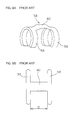
- an anti-rattle member as shown in Fig.8 has heretofor been proposed (Unexamined Japanese Utility Model No.7(1995)-40360).
- the anti-rattle member is arranged such that one shaft section 51 is formed with a thick shaft portion 52 at an end thereof, which is formed with a male serration 53, while a female serration 54 for fittingly receiving the male serration 53 is formed at an inner circumferential surface of a fit hole 56 of the other shaft section 55.
- the male serration 53 includes a first portion 53a and a second portion 53b which are axially separated from each other.
- a thin shaft portion 57 is defined between the first and second portions 53a, 53b and is adapted to be brought into fitting engagement with an anti-rattle member 58.
- the anti-rattle member 58 includes two legs 59 substantially of an annular shape (C-shape) having a smaller inside diameter than an outside diameter of the thin shaft portion, and a body 60 interconnecting these legs 59 at their mid portions.
- the anti-rattle member 58 When the one shaft section 51 is inserted in the fit hole 56 of the other shaft section 55, the anti-rattle member 58 is stably retained on the one shaft section 51 by way of the legs 59 resiliently clamping the thin shaft portion 57. This eliminates a fear of disengagement of the anti-rattle member 58 during assembly.
- the body 60 is of a bent shape raised at its intermediate portion.
- the body is designed to prevent the occurrence of rattle by way of its top portion resiliently pressing against the female serration 54.
- the thin shaft portion 57 is increased in the axial length because of the anti-rattle member 58 having the pair of legs 59, 59 axially spaced from each other by a distance D.
- the male serration 53 is increased in the overall axial length.
- a fit length between the pair of shaft sections 51, 55 is increased so that the overall weight and costs of the expansion shaft increase.
- an expansion shaft comprises a first and a second shaft section aligned on the same axis, the expansion shaft further comprising a fit hole formed at the first shaft section for receiving the second shaft section; a thin shaft portion defined on the second shaft section; a pair of thick shaft portions formed on the second shaft section as axially sandwiching the thin shaft portion therebetween; a groove and a ridge respectively formed in an inner circumferential surface of the fit hole and on the thick shaft portions for coming into fitting engagement thereby integrally rotatably interconnecting the first and second shaft sections as allowing the shaft sections to axially move relative to each other; and a resilient member interposed between the inner circumferential surface of the fit hole of the first shaft section and an opposite outer peripheral surface of the second shaft section for preventing the shaft sections from radially moving relative to each other.
- the resilient member includes a single C-shaped snap ring resiliently clamping the thin shaft portion, and an arm extended from the snap ring in at least one axial direction of the second shaft section and serving to press against the inner circumferential surface of the fit hole of the first shaft section.
- the single C-shaped snap ring is used for retaining the resilient member on the thin shaft portion of the second shaft section so that the thin shaft portion can be reduced in the axial length.
- This contributes to the reduction of the fit length between the first and second shaft sections, thus enabling the realization of a compact, lightweight expansion shaft.
- the arm resiliently presses against the inner circumferential surface of the fit hole of the first shaft section thereby positively preventing the vibrations due to a loose fit between the first and second shaft sections as well as the occurrence of noise associated with the vibrations.
- the expansion shaft is constructed such that a fit hole 4 with a female serration 3 is formed at an end 2 of a first shaft section 1 while an end 7 of a second shaft section 6 is inserted in the fit hole 4, the end 7 of the second shaft section 6 having a male serration 5 to engage with the female serration 3.
- the end 7 of the second shaft section 6 includes a thin shaft portion 8 having a smaller diameter and a predetermined width, and a pair of thick shaft portions 16, 17 of a greater diameter axially sandwiching the thin shaft portion 8 therebetween.
- the thick shaft portions 16, 17 are respectively formed with a male serration 5a, 5b at their outer peripheries. That is, the male serration 5 is divided into the two male serrations 5a, 5b disposed on axially opposite sides of the thin shaft portion 8.
- Fig.1 schematically shows the male serrations 5a, 5b and the female serration 3.
- An anti-rattle member 9 formed of a resilient member is mounted on the thin shaft portion 8.
- the anti-rattle member 9 is constructed from a sheet metal by press forming.
- the anti-rattle member 9 includes a leg portion 10 serving as a single snap ring substantially of an annular form (C-shaped arcuate form) extending along a circumference of the thin shaft portion 8, and a pair of arms 11, 12 extended from an intermediate portion (a midportion, for example) of the leg portion 10 in axially opposite directions of the thin shaft portion 8.
- the leg portion 10 extends substantially along the overall circumference of the thin shaft portion 8, resiliently clamping the thin shaft portion 8.
- Each of the arms 11, 12 is of a bent form, raised at its intermediate portion 13 such that the intermediate portion 13 may resiliently contact the female serration 3, as shown in Fig.4, when the two shaft sections 1, 6 are assembled.
- the male serrations 5a, 5b are respectively formed with teeth-free areas 14, 15 for accommodating the corresponding arms 11, 12.
- each serration tooth 18 defines a ridge, the serration tooth extending axially of the male serration 5a and having a triangular shape in section.
- Each serration tooth 18 as the ridge of the male serration 5a is fitted in a groove 20 defined between adjoining serration teeth 19 of the female serration 3.
- an axial length L1 of the thin shaft portion 8 can be reduced because a single leg portion 10 serves to retain the anti-rattle member 9 on the thin shaft portion 8 of the second shaft section 6. This contributes to a reduced fit length L2 between the serrations 3, 5 (see Fig.3B) and hence, to the realization of a compact, lightweight expansion shaft.
- a sufficient anti-rattle effect can be attained by virtue of the pair of arms 11, 12 pressing against the female serration 3, the arms extended axially of the thin shaft portion 8 in a bent fashion.
- the arms 11, 12 are accommodated in the corresponding teeth-free areas 14, 15 of the male serrations 5a, 5b so that the arms 11, 12 may not interfere with the assembly of the shaft sections.
- the assembly of the expansion shaft is facilitated.
- an anti-rattle member 9A may include either one of the arms 11, 12. Such a design requires only one teeth-free area, further reducing the production costs.
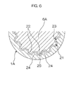
- a second shaft section 6A may comprise a spline shaft.
- each spline tooth 22 defines the ridge, the spline tooth extending on a male spline 21 of the second shaft section 6A and having a trapezoidal or groove-like shape in section.
- a groove 25 is defined between adjoining spline teeth 24 of a female spline 23 of a first shaft section 1A.
- the male serration 5 may be coated with a synthetic resin of low friction coefficient such as fluoroplastics to provide a coating film 26.
- the synthetic-resin coating film 26 serves to reduce sliding resistance between the serrations 3, 5. Particularly, quite a great anti-rattle effect can be attained at low costs because the synthetic-resin coating film 26 not only serves to reduce the clearance between the serrations 3, 5 but also cooperates with the anti-rattle member 9 to prevent the occurrence of rattle. The reasons for this are the following.
Landscapes
- Engineering & Computer Science (AREA)
- General Engineering & Computer Science (AREA)
- Mechanical Engineering (AREA)
- Ocean & Marine Engineering (AREA)
- Steering Controls (AREA)
- Snaps, Bayonet Connections, Set Pins, And Snap Rings (AREA)
- Springs (AREA)
Abstract
Description
Claims (9)
- An expansion shaft comprising a first and a second shaft section (1, 1A, 6, 6A) aligned on the same axis, the expansion shaft further comprising:a fit hole (4) formed at the first shaft section (1, 1A) for receiving the second shaft section (6, 6A) ;a thin shaft portion (8) defined on the second shaft section (6, 6A);a pair of thick shaft portions (16, 17) formed on the second shaft section (1, 1A) as axially sandwiching the thin shaft portion (8) on the second shaft section (6, 6A) therebetween;a groove (20, 25) and a ridge (18, 22) respectively formed in an inner circumferential surface of the fit hole (4) and on the thick shaft portions (16, 17) adapted to come into fitting engagement thereby integrally rotatably interconnecting the first and second shaft sections (1, 1A, 6, 6A) as allowing the shaft sections to axially move relatively to each other; anda resilient member (9, 9A) interposed between the inner circumferential surface of the fit hole (4) of the first shaft section (1, 1A) and an opposite outer peripheral surface of the second shaft section (6, 6A) for preventing the shaft sections (1, 1A, 6, 6A) from radially moving relative to each other,wherein the resilient member (9, 9A) includes a single C-shaped snap ring (10) resiliently clamping the thin shaft portion (8), and an arm (11, 12) extending from the snap ring (10) in at least one axial direction of the second shaft section (6, 6A) and adapted to press against the inner circumferential surface of the fit hole (4) of the first shaft section (1, 1A).
- The shaft according to claim 1,
wherein at least one of the thick shaft portions (16, 17) of the second shaft section (6, 6A) includes ridge-free areas (14, 15) capable of accommodating a corresponding arm (11, 12). - The shaft according to claim 2,
wherein the ridge-free area (14, 15) is continous to the thin shaft portion (8). - The shaft according to any of claims 1 to 3,
wherein the second shaft section (6, 6A) includes a spline shaft (6A). - The shaft according to any of claims 1 to 3,
wherein the second shaft section (6, 6A) includes a serration shaft (6). - The shaft according to any of claims 1 to 5,
wherein a synthetic-resin layer (26) is interposed between the ridge (18, 22) and the groove (20, 25). - The shaft according to claim 6,
wherein the synthetic-resin layer (26) is laid over a region at least including the thick shaft portions (16, 17) of the second shaft section (6, 6A). - The shaft according to claim 6,
wherein the synthetic-resin layer (26) is laid over a region at least including the groove (20, 25) in the inner circumferential surface of the fit hole (4). - The shaft according to any of claims 1 to 8,
wherein the resilient member (9) includes a sheet metal formed by press forming.
Applications Claiming Priority (4)
| Application Number | Priority Date | Filing Date | Title |
|---|---|---|---|
| JP34370099 | 1999-12-02 | ||
| JP34370099 | 1999-12-02 | ||
| JP2000350738A JP3853150B2 (en) | 1999-12-02 | 2000-11-17 | Telescopic shaft |
| JP2000350738 | 2000-11-17 |
Publications (3)
| Publication Number | Publication Date |
|---|---|
| EP1106847A2 true EP1106847A2 (en) | 2001-06-13 |
| EP1106847A3 EP1106847A3 (en) | 2002-09-18 |
| EP1106847B1 EP1106847B1 (en) | 2004-03-31 |
Family
ID=26577590
Family Applications (1)
| Application Number | Title | Priority Date | Filing Date |
|---|---|---|---|
| EP00126222A Expired - Lifetime EP1106847B1 (en) | 1999-12-02 | 2000-11-30 | Telescopic shaft |
Country Status (4)
| Country | Link |
|---|---|
| US (1) | US6428236B2 (en) |
| EP (1) | EP1106847B1 (en) |
| JP (1) | JP3853150B2 (en) |
| DE (1) | DE60009427T2 (en) |
Cited By (6)
| Publication number | Priority date | Publication date | Assignee | Title |
|---|---|---|---|---|
| EP1500832A1 (en) * | 2003-07-23 | 2005-01-26 | Koyo Seiko Co., Ltd. | Extendable shaft |
| US7198425B2 (en) | 2002-02-25 | 2007-04-03 | Ford Global Technologies, Llc | Steering shaft coupling for automotive vehicle |
| EP1845273A3 (en) * | 2006-04-12 | 2010-10-13 | ZF Friedrichshafen AG | Connection assembly for a rotationally fixed connection of two components in the drive train of a vehicle |
| US20160236735A1 (en) * | 2014-03-05 | 2016-08-18 | Komatsu Ltd. | Roller device and roller shell for track-type work vehicle |
| IT201700065554A1 (en) * | 2017-06-13 | 2018-12-13 | Rielda Serrature S P A | INTERNAL BODY-BODY GROUP CABLE PREFERABLY FOR LOCK |
| FR3106292A1 (en) * | 2020-01-21 | 2021-07-23 | Safran Aircraft Engines | Tool to aid the coupling of two turbomachine shafts and method of coupling these two shafts |
Families Citing this family (36)
| Publication number | Priority date | Publication date | Assignee | Title |
|---|---|---|---|---|
| DE19954969A1 (en) * | 1999-11-16 | 2001-06-07 | Bosch Gmbh Robert | Device for connecting a shaft to a ring |
| US6551009B2 (en) * | 2001-04-26 | 2003-04-22 | General Electric Company | Spline connection for limited access space and method of assembly and disassembly |
| US7320742B2 (en) * | 2002-05-07 | 2008-01-22 | O'neill Kevin J | Packaging device and method for absorbing moisture |
| US20050173914A1 (en) * | 2002-06-19 | 2005-08-11 | Nsk Ltd. | Shock absorbing steering column unit for vehicle |
| KR100792820B1 (en) * | 2002-07-03 | 2008-01-14 | 주식회사 만도 | Serration device for shaft connection |
| JP4454368B2 (en) * | 2004-03-31 | 2010-04-21 | 愛知機械工業株式会社 | Rotating member mounting structure |
| US7070357B2 (en) * | 2004-06-07 | 2006-07-04 | Eastman Kodak Company | D-shaped slot having a relief |
| WO2006009230A1 (en) * | 2004-07-21 | 2006-01-26 | Nsk Ltd. | Telescopic shaft for vehicle steering |
| EP1918510B8 (en) * | 2005-06-29 | 2012-03-14 | Panasonic Corporation | Fluid machine and refrigeration cycle device |
| US7500697B2 (en) * | 2006-01-27 | 2009-03-10 | Gm Global Technology Operations, Inc. | Snap ring locking clip and method |
| US20080054696A1 (en) * | 2006-09-05 | 2008-03-06 | Mcconnell Thomas E | Infant seat |
| FR2909146B1 (en) * | 2006-11-28 | 2009-06-05 | Snecma Sa | DEVICE FOR CONNECTING TWO ROTARY TREES, PARTICULARLY IN A TURBOMACHINE. |
| EP2151541A4 (en) * | 2007-05-16 | 2012-06-27 | Panasonic Corp | INTEGRATED EXTENSION COMPRESSOR AND REFRIGERATION CYCLE DEVICE HAVING THE SAME |
| US8371660B2 (en) * | 2007-06-19 | 2013-02-12 | William B. Shook | Load transmitting insert for a soft spline body |
| TW200900323A (en) * | 2007-06-19 | 2009-01-01 | William Blair Shook | Steel insert for aluminum spline body |
| TWM331451U (en) * | 2007-11-09 | 2008-05-01 | Xero Engineering Inc | Protection structure of the gear sleeve of a hub |
| US20100029397A1 (en) * | 2008-07-29 | 2010-02-04 | Schneider Paul E | Slip joint for use in a drive train system |
| TWI393641B (en) * | 2010-01-19 | 2013-04-21 | Joy Ind Co Ltd | Bicycle of the ratchet sleeve structure |
| US20110193406A1 (en) * | 2010-02-09 | 2011-08-11 | Joy Industrial Co., Ltd. | Tubular portion of bicycle hub |
| TWI415753B (en) * | 2010-06-15 | 2013-11-21 | William B Shook | Drive body for bicycle wheel hub |
| JP5641333B2 (en) * | 2011-01-25 | 2014-12-17 | 株式会社ジェイテクト | Telescopic shaft and vehicle steering device |
| CN102506082B (en) * | 2011-09-30 | 2014-12-10 | 陕西法士特齿轮有限责任公司 | Method and device for positioning gears on shaft |
| KR20150031274A (en) * | 2012-06-19 | 2015-03-23 | 니타 가부시키가이샤 | Structural body for shaft, male member, and female member |
| US20140119822A1 (en) * | 2012-10-30 | 2014-05-01 | Sir Meccanica S.P.A. | Modular shaft for machine tools |
| US20140119810A1 (en) * | 2012-10-31 | 2014-05-01 | Melvin Lee Tinnin | Steering wheel shaft retention mechanism assembly and service tool |
| US20140116184A1 (en) * | 2012-10-31 | 2014-05-01 | Michael W. Clark | Steering wheel retention assembly |
| US10030711B2 (en) * | 2013-01-07 | 2018-07-24 | Ford Global Technologies, Llc | Preventing noise from mating spline teeth |
| DE102015109872A1 (en) * | 2015-06-19 | 2016-12-22 | Dr. Ing. H.C. F. Porsche Aktiengesellschaft | Shaft-hub connection and torque transmission device with at least one shaft-hub connection |
| US10151352B2 (en) * | 2015-11-20 | 2018-12-11 | GM Global Technology Operations LLC | Shaft retention apparatus |
| US9821843B1 (en) * | 2017-01-06 | 2017-11-21 | Robert Bosch Automotive Steering Llc | Tie rod |
| US11053983B2 (en) * | 2018-01-19 | 2021-07-06 | The Boeing Company | Torque tube assemblies for use with aircraft high lift devices |
| JP7119841B2 (en) * | 2018-09-27 | 2022-08-17 | 日本精工株式会社 | Telescopic shaft with stopper |
| JP7356384B2 (en) * | 2020-03-24 | 2023-10-04 | 株式会社ジェイテクトコラムシステム | Shaft coupling structure |
| US11879503B2 (en) * | 2020-08-04 | 2024-01-23 | Raytheon Company | Rotationally stiff key for coupling non-parallel shafts |
| US20240240674A1 (en) * | 2023-01-12 | 2024-07-18 | Steering Solutions Ip Holding Corporation | Steering shaft assembly |
| US20240175462A1 (en) * | 2022-11-30 | 2024-05-30 | Steering Solutions Ip Holding Corporation | Steering shaft assembly |
Family Cites Families (11)
| Publication number | Priority date | Publication date | Assignee | Title |
|---|---|---|---|---|
| US3964833A (en) * | 1975-05-21 | 1976-06-22 | The Singer Company | Keyed retainer |
| JPS60102524U (en) * | 1983-12-19 | 1985-07-12 | 日産自動車株式会社 | steering device |
| CN1046018C (en) * | 1993-05-03 | 1999-10-27 | 托林顿公司 | Variable length shaft assembly |
| JP3226388B2 (en) | 1993-07-30 | 2001-11-05 | オリンパス光学工業株式会社 | Molding method of composite optical element |
| JP2935950B2 (en) * | 1993-12-03 | 1999-08-16 | 株式会社山田製作所 | Steering shaft and apparatus for manufacturing the same |
| JP2593916Y2 (en) * | 1993-12-28 | 1999-04-19 | 富士機工株式会社 | Serration fitting structure of telescopic shaft |
| JP3341961B2 (en) * | 1994-02-28 | 2002-11-05 | 株式会社ユニシアジェックス | Shaft coupling structure |
| DE19715845A1 (en) * | 1996-04-26 | 1997-10-30 | Volkswagen Ag | Steering column for passenger motor cars |
| JPH1053144A (en) * | 1996-08-09 | 1998-02-24 | Toyota Motor Corp | Telescopic steering device |
| US6257798B1 (en) * | 1999-05-07 | 2001-07-10 | Gkn Automotive, Inc. | Universal joint coupling |
| US6241616B1 (en) * | 1999-05-20 | 2001-06-05 | Neapco Inc. | Variable length double telescoping drive shaft assembly |
-
2000
- 2000-11-17 JP JP2000350738A patent/JP3853150B2/en not_active Expired - Fee Related
- 2000-11-30 DE DE60009427T patent/DE60009427T2/en not_active Expired - Fee Related
- 2000-11-30 EP EP00126222A patent/EP1106847B1/en not_active Expired - Lifetime
- 2000-12-01 US US09/726,326 patent/US6428236B2/en not_active Expired - Fee Related
Cited By (8)
| Publication number | Priority date | Publication date | Assignee | Title |
|---|---|---|---|---|
| US7198425B2 (en) | 2002-02-25 | 2007-04-03 | Ford Global Technologies, Llc | Steering shaft coupling for automotive vehicle |
| EP1500832A1 (en) * | 2003-07-23 | 2005-01-26 | Koyo Seiko Co., Ltd. | Extendable shaft |
| US7172361B2 (en) | 2003-07-23 | 2007-02-06 | Koyo Seiko Co., Ltd. | Extendable shaft |
| EP1845273A3 (en) * | 2006-04-12 | 2010-10-13 | ZF Friedrichshafen AG | Connection assembly for a rotationally fixed connection of two components in the drive train of a vehicle |
| US20160236735A1 (en) * | 2014-03-05 | 2016-08-18 | Komatsu Ltd. | Roller device and roller shell for track-type work vehicle |
| US10086889B2 (en) * | 2014-03-05 | 2018-10-02 | Komatsu Ltd. | Roller device and roller shell for track-type work vehicle |
| IT201700065554A1 (en) * | 2017-06-13 | 2018-12-13 | Rielda Serrature S P A | INTERNAL BODY-BODY GROUP CABLE PREFERABLY FOR LOCK |
| FR3106292A1 (en) * | 2020-01-21 | 2021-07-23 | Safran Aircraft Engines | Tool to aid the coupling of two turbomachine shafts and method of coupling these two shafts |
Also Published As
| Publication number | Publication date |
|---|---|
| US6428236B2 (en) | 2002-08-06 |
| DE60009427T2 (en) | 2004-12-30 |
| EP1106847B1 (en) | 2004-03-31 |
| US20010002966A1 (en) | 2001-06-07 |
| DE60009427D1 (en) | 2004-05-06 |
| JP3853150B2 (en) | 2006-12-06 |
| EP1106847A3 (en) | 2002-09-18 |
| JP2001221245A (en) | 2001-08-17 |
Similar Documents
| Publication | Publication Date | Title |
|---|---|---|
| EP1106847B1 (en) | Telescopic shaft | |
| JP3341961B2 (en) | Shaft coupling structure | |
| EP1553005B1 (en) | Extendable vehicle steering shaft | |
| JP3646556B2 (en) | Elastic shaft coupling | |
| US7172361B2 (en) | Extendable shaft | |
| JP3627441B2 (en) | Elastic shaft coupling | |
| US5916026A (en) | Elastic universal joint | |
| US20040121846A1 (en) | Coupling arrangement | |
| JP2603035Y2 (en) | Fixed structure of outer ring of one-way clutch | |
| JP2003306152A (en) | Intermediate shaft for vehicle steering | |
| JP4279054B2 (en) | Telescopic shaft | |
| JP2005114068A (en) | Spline joint | |
| JP2593916Y2 (en) | Serration fitting structure of telescopic shaft | |
| JP4308491B2 (en) | Steering device | |
| JP2578378Y2 (en) | Support structure of intermediate bearing for propeller shaft | |
| EP0739806A2 (en) | Vehicle steering column with axially slidable coupling | |
| JPH0138669Y2 (en) | ||
| JP3508003B2 (en) | One-way clutch | |
| JP2554915Y2 (en) | Synchronous meshing device | |
| JPH0323767B2 (en) | ||
| JPH0642130Y2 (en) | Resin transmission wheel | |
| JPH081298Y2 (en) | One way clutch | |
| JP2001158364A (en) | Telescopic shaft | |
| JPH0880704A (en) | Drive shaft | |
| JP3427326B2 (en) | One-way clutch |
Legal Events
| Date | Code | Title | Description |
|---|---|---|---|
| PUAI | Public reference made under article 153(3) epc to a published international application that has entered the european phase |
Free format text: ORIGINAL CODE: 0009012 |
|
| AK | Designated contracting states |
Kind code of ref document: A2 Designated state(s): AT BE CH CY DE DK ES FI FR GB GR IE IT LI LU MC NL PT SE TR |
|
| AX | Request for extension of the european patent |
Free format text: AL;LT;LV;MK;RO;SI |
|
| PUAL | Search report despatched |
Free format text: ORIGINAL CODE: 0009013 |
|
| RIC1 | Information provided on ipc code assigned before grant |
Free format text: 7F 16C 3/03 A, 7F 16D 3/06 B, 7B 62D 1/18 B |
|
| AK | Designated contracting states |
Kind code of ref document: A3 Designated state(s): AT BE CH CY DE DK ES FI FR GB GR IE IT LI LU MC NL PT SE TR |
|
| AX | Request for extension of the european patent |
Free format text: AL;LT;LV;MK;RO;SI |
|
| 17P | Request for examination filed |
Effective date: 20020909 |
|
| AKX | Designation fees paid |
Designated state(s): DE FR GB |
|
| GRAP | Despatch of communication of intention to grant a patent |
Free format text: ORIGINAL CODE: EPIDOSNIGR1 |
|
| GRAS | Grant fee paid |
Free format text: ORIGINAL CODE: EPIDOSNIGR3 |
|
| GRAA | (expected) grant |
Free format text: ORIGINAL CODE: 0009210 |
|
| RIN1 | Information on inventor provided before grant (corrected) |
Inventor name: HIRAKUSHI, SHUUZOU Inventor name: HASHIMOTO, TAKAYOSHI Inventor name: AOTA, KENICHI Inventor name: WATANABE, JUNYA |
|
| AK | Designated contracting states |
Kind code of ref document: B1 Designated state(s): DE FR GB |
|
| RAP1 | Party data changed (applicant data changed or rights of an application transferred) |
Owner name: KOYO SEIKO CO., LTD. |
|
| REG | Reference to a national code |
Ref country code: GB Ref legal event code: FG4D |
|
| REG | Reference to a national code |
Ref country code: IE Ref legal event code: FG4D |
|
| REF | Corresponds to: |
Ref document number: 60009427 Country of ref document: DE Date of ref document: 20040506 Kind code of ref document: P |
|
| ET | Fr: translation filed | ||
| PLBE | No opposition filed within time limit |
Free format text: ORIGINAL CODE: 0009261 |
|
| STAA | Information on the status of an ep patent application or granted ep patent |
Free format text: STATUS: NO OPPOSITION FILED WITHIN TIME LIMIT |
|
| 26N | No opposition filed |
Effective date: 20050104 |
|
| PGFP | Annual fee paid to national office [announced via postgrant information from national office to epo] |
Ref country code: DE Payment date: 20071122 Year of fee payment: 8 |
|
| PGFP | Annual fee paid to national office [announced via postgrant information from national office to epo] |
Ref country code: FR Payment date: 20071108 Year of fee payment: 8 Ref country code: GB Payment date: 20071128 Year of fee payment: 8 |
|
| GBPC | Gb: european patent ceased through non-payment of renewal fee |
Effective date: 20081130 |
|
| REG | Reference to a national code |
Ref country code: FR Ref legal event code: ST Effective date: 20090731 |
|
| PG25 | Lapsed in a contracting state [announced via postgrant information from national office to epo] |
Ref country code: DE Free format text: LAPSE BECAUSE OF NON-PAYMENT OF DUE FEES Effective date: 20090603 |
|
| PG25 | Lapsed in a contracting state [announced via postgrant information from national office to epo] |
Ref country code: GB Free format text: LAPSE BECAUSE OF NON-PAYMENT OF DUE FEES Effective date: 20081130 |
|
| PG25 | Lapsed in a contracting state [announced via postgrant information from national office to epo] |
Ref country code: FR Free format text: LAPSE BECAUSE OF NON-PAYMENT OF DUE FEES Effective date: 20081130 |